
Related Manuals for Cincoze CV-W115FH/P1301 Series


Summary of Contents for Cincoze CV-W115FH/P1301 Series
- Page 1 CV-100/P1301 Series User Manual Power Efficient Industrial Panel PC 8.4”~24”TFT LCD Panel PC with Intel® Alder Lake-N Series Processor Version: V1.23...
-
Page 2: Table Of Contents
1.2.3 CV-110H/P1301 Series ......................30 1.2.4 CV-112H/P1301 Series ......................35 1.2.5 CV-115/P1301 Series ........................ 40 1.2.6 CV-W115/P1301 Series ......................45 1.2.7 CV-W115FH/P1301 Series ......................50 1.2.8 CV-117/P1301 Series ........................ 55 1.2.9 CV-119/P1301 Series ........................ 60 1.2.10 CV-W121/P1301 Series ......................65 1.2.11 CV-W124/P1301 Series ...................... - Page 3 2.5 Optional Module Pin Definition & Settings ................86 2.5.1 CFM-IGN101 Module ........................ 86 Chapter 3 System Setup ........................87 3.1 Removing Top Cover ......................88 3.2 Installing SO-DIMM Memory ....................89 3.3 Installing M.2 Key B Card ...................... 90 3.3.1 M.2 Key B type 3052 .........................
- Page 4 4.4.2 PCH-IO Configuration ......................124 4.5 Security Setup ........................126 4.6 Boot Setup .......................... 127 4.7 Save & Exit .......................... 128 Chapter 5 Product Application ......................129 5.1 Where to download drivers? ..................... 130 5.2 Where to find the technical documents? ................130 CV-100/P1301 Series | User Manual...
-
Page 5: Preface
2025/03/28 Copyright Notice © 2024 by Cincoze Co., Ltd. All rights are reserved. No parts of this manual may be copied, modified, or reproduced in any form or by any means for commercial use without the prior written permission of Cincoze Co., Ltd. All information and specification provided in this manual are for reference only and remain subject to change without prior notice. -
Page 6: Declaration Of Conformity
(such as a fuse, battery, etc.), are not warranted. Before sending your product in, you will need to fill in Cincoze RMA Request Form and obtain an RMA number from us. Our staff is available at any time to provide you with the most friendly and immediate service. -
Page 7: Technical Support And Assistance
Limitation of Liability Cincoze’ liability arising out of the manufacture, sale, or supplying of the product and its use, whether based on warranty, contract, negligence, product liability, or otherwise, shall not exceed the original selling price of the product. The remedies provided herein are the customer’s sole and exclusive remedies. -
Page 8: Conventions Used In This Manual
Conventions Used in this Manual This indication alerts operators to an operation that, if not strictly observed, may result in severe injury. (Cette indication avertit les opérateurs d'une opération qui, si elle n'est pas strictement observée, peut entraîner des blessures graves.) This indication alerts operators to an operation that, if not strictly observed, may result in safety hazards to personnel or damage to equipment. -
Page 9: Package Contents
If one of the following situations arises, get the equipment checked by service personnel: ⚫ The power cord or plug is damaged. ⚫ Liquid has penetrated into the equipment. ⚫ The equipment has been exposed to moisture. ⚫ The equipment does not work well, or you cannot get it work according to the user's manual. -
Page 10: Ordering Information
Ordering Information Available Models Model No. Product Description 8.4“ TFT-LCD SVGA 4:3 Panel PC with Intel® Core i3-N305 CV-108R/P1301-i3 Octa Core Slim Embedded Computer and Resistive 5-wire Touch 8.4“ TFT-LCD SVGA 4:3 Panel PC with Intel® Core i3-N305 CV-108C/P1301-i3 Octa Core Slim Embedded Computer and P-Cap. Touch 8.4“... - Page 11 10.4“ TFT-LCD XGA 4:3 Panel PC with Intel® Core i3-N305 CV-110HR/P1301-i3 Octa Core Slim Embedded Computer and Resistive 5-wire Touch 10.4“ TFT-LCD XGA 4:3 Panel PC with Intel® Core i3-N305 CV-110HC/P1301-i3 Octa Core Slim Embedded Computer and P-Cap. Touch 10.4" TFT-LCD XGA 4:3 Panel PC with Intel® Processor CV-110HR/P1301-N97 N97 Quad Core Slim Embedded Computer and Resistive 5-wire Touch...
- Page 12 15“ TFT-LCD XGA 4:3 Panel PC with Intel® Core i3-N305 CV-115C/P1301-i3 Octa Core Slim Embedded Computer and P-Cap. Touch 15" TFT-LCD XGA 4:3 Panel PC with Intel® Core i3-N305 CV-115C-AG/P1301-i3- R10 Octa-Core Processor, P-Cap Touch, and Anti-Glare Coating. 15" TFT-LCD XGA 4:3 Panel PC with Intel® Processor N97 CV-115R/P1301-N97 Quad Core Slim Embedded Computer and Resistive 5-wire Touch...
- Page 13 17" TFT-LCD SXGA 5:4 Panel PC with Intel® Atom® CV-117R/P1301-X7425E x7425E Quad Core Slim Embedded Computer and Resistive 5-wire Touch 17" TFT-LCD SXGA 5:4 Panel PC with Intel® Atom® CV-117C/P1301-X7425E x7425E Quad Core Slim Embedded Computer and P-Cap. Touch 17" TFT-LCD SXGA 5:4 Panel PC with Intel® Atom® CV-117G/P1301-X7425E x7425E Quad Core Slim Embedded Computer and without Touch...
- Page 14 15.6“ TFT-LCD WXGA 16:9 Panel PC with Intel® Core CV-W115C/P1301-i3 i3-N305 Octa Core Slim Embedded Computer and P-Cap. Touch 15.6" TFT-LCD WXGA 16:9 Panel PC with Intel® Processor CV-W115R/P1301-N97 N97 Quad Core Slim Embedded Computer and Resistive 5-wire Touch 15.6" TFT-LCD WXGA 16:9 Panel PC with Intel® Processor CV-W115C/P1301-N97 N97 Quad Core Slim Embedded Computer and P-Cap.
- Page 15 21.5“ TFT-LCD Full HD 16:9 Panel PC with Intel® Core CV-W121G/P1301-i3 i3-N305 Octa Core Slim Embedded Computer and without Touch 21.5" TFT-LCD Full HD 16:9 Panel PC with Intel® CV-W121R/P1301-N97 Processor N97 Quad Core Slim Embedded Computer and Resistive 5-wire Touch 21.5"...
- Page 16 24" TFT-LCD Full HD 16:9 Panel PC with Intel® Atom® CV-W124R/P1301-X7425E x7425E Quad Core Slim Embedded Computer and Resistive 5-wire Touch 24" TFT-LCD Full HD 16:9 Panel PC with Intel® Atom® CV-W124C/P1301-X7425E x7425E Quad Core Slim Embedded Computer and P-Cap. Touch 24"...
-
Page 17: Chapter 1 Product Introductions
Chapter 1 Product Introductions CV-100/P1301 Series | User Manual... -
Page 18: Overview
M.2 Key B Type 3052 and M .2 Key E Type 2230 expansion slots, and supports the exclusive CFM expansion module to add PoE and IGN functions. Cincoze’s exclusive CDS patented technology provides flexibility for future computer performance upgrades or display replacements. - Page 19 Complete Product Portfolio The CV-100/P1301 series has a diverse product portfolio, ranging from screen size (8.4 to 24 inches), display ratio (4:3, 5:4, and 16:9) to touch methods (multi-point P-Cap and single-point resistive), which can be selected based on application requirements.
-
Page 20: Specifications
1.2 Specifications 1.2.1 CV-108/P1301 Series Model Name CV-108R CV-108C Display • 8.4" (4:3) LCD Size • 800 x 600 Max. Resolution • 400 Brightness (cd/m2) • 600 : 1 Contrast Ratio • 262K LCD Color • 0.213 (H) x 0.213 (V) Pixel Pitch(mm) •... - Page 21 • UL, cUL, CB, IEC, EN 62368-1 Safety Model Name P1301 System • Onboard Intel® Alder Lake-N Series Processor: - Intel® Core™ i3-N305 8 Cores Up to 3.80 GHz, TDP 15W Processor - Intel® Processor N97 4 Cores Up to 3.60 GHz, TDP 12W - Intel Atom®...
- Page 22 Other Function • 1x Clear CMOS Switch Clear CMOS Switch • 1x Reset Button Reset Button • Support 0.2sec Instant Reboot Technology Instant Reboot • Software Programmable Supports 256 Levels System Reset Watchdog Timer • LCD On/Off, Brightness Up, Brightness Down OSD Button •...
- Page 23 • UL, cUL, CB, IEC, EN62368-1 Safety * Product Specifications and features are for reference only and are subject to change without prior notice. For more information, please refer to the latest product datasheet from Cincoze's website. CV-100/P1301 Series | User Manual...
- Page 24 Dimension CV-108/P1301 Unit: mm CV-100/P1301 Series | User Manual...
-
Page 25: Cv-110/P1301 Series
1.2.2 CV-110/P1301 Series Model Name CV-110R CV-110C Display • 10.4" (4:3) LCD Size • 800 x 600 Max. Resolution • 400 Brightness (cd/m2) • 700 : 1 Contrast Ratio • 16.2M LCD Color • Pixel Pitch(mm) 0.264 (H) x 0.264 (V) •... - Page 26 Model Name P1301 System • Onboard Intel® Alder Lake-N Series Processor: - Intel® Core™ i3-N305 8 Cores Up to 3.80 GHz, TDP 15W Processor - Intel® Processor N97 4 Cores Up to 3.60 GHz, TDP 12W - Intel Atom® x7425E 4 Cores Up to 3.40 GHz, TDP 12W •...
- Page 27 • 1x Clear CMOS Switch Clear CMOS Switch • 1x Reset Button Reset Button • Support 0.2sec Instant Reboot Technology Instant Reboot • Software Programmable Supports 256 Levels System Reset Watchdog Timer • LCD On/Off, Brightness Up, Brightness Down OSD Button •...
- Page 28 • UL, cUL, CB, IEC, EN62368-1 Safety * Product Specifications and features are for reference only and are subject to change without prior notice. For more information, please refer to the latest product datasheet from Cincoze's website. CV-100/P1301 Series | User Manual...
- Page 29 Dimension CV-110/P1301 Unit: mm CV-100/P1301 Series | User Manual...
-
Page 30: Cv-110H/P1301 Series
1.2.3 CV-110H/P1301 Series Model Name CV-110HR CV-110HC Display • 10.4" (4:3) LCD Size • Max. Resolution 1024 x 768 • 470 Brightness (cd/m2) • Contrast Ratio 1000 : 1 • 16.2M LCD Color • Pixel Pitch(mm) 0.2055 (H) x 0.2055 (V) •... - Page 31 Model Name P1301 System • Onboard Intel® Alder Lake-N Series Processor: - Intel® Core™ i3-N305 8 Cores Up to 3.80 GHz, TDP 15W Processor - Intel® Processor N97 4 Cores Up to 3.60 GHz, TDP 12W - Intel Atom® x7425E 4 Cores Up to 3.40 GHz, TDP 12W •...
- Page 32 • 1x Clear CMOS Switch Clear CMOS Switch • 1x Reset Button Reset Button • Support 0.2sec Instant Reboot Technology Instant Reboot • Software Programmable Supports 256 Levels System Reset Watchdog Timer • LCD On/Off, Brightness Up, Brightness Down OSD Button •...
- Page 33 • UL, cUL, CB, IEC, EN62368-1 Safety * Product Specifications and features are for reference only and are subject to change without prior notice. For more information, please refer to the latest product datasheet from Cincoze's website. CV-100/P1301 Series | User Manual...
- Page 34 Dimension CV-110H/P1301 Unit: mm CV-100/P1301 Series | User Manual...
-
Page 35: Cv-112H/P1301 Series
1.2.4 CV-112H/P1301 Series Model Name CV-112HR CV-112HC Display • 12.1" (4:3) LCD Size • Max. Resolution 1024 x 768 • 500 Brightness (cd/m2) • Contrast Ratio 700 : 1 • 16.2M LCD Color • Pixel Pitch(mm) 0.24 (H) x 0.24 (V) •... - Page 36 Model Name P1301 System • Onboard Intel® Alder Lake-N Series Processor: - Intel® Core™ i3-N305 8 Cores Up to 3.80 GHz, TDP 15W Processor - Intel® Processor N97 4 Cores Up to 3.60 GHz, TDP 12W - Intel Atom® x7425E 4 Cores Up to 3.40 GHz, TDP 12W •...
- Page 37 • 1x Clear CMOS Switch Clear CMOS Switch • 1x Reset Button Reset Button • Support 0.2sec Instant Reboot Technology Instant Reboot • Software Programmable Supports 256 Levels System Reset Watchdog Timer • LCD On/Off, Brightness Up, Brightness Down OSD Button •...
- Page 38 • UL, cUL, CB, IEC, EN62368-1 Safety * Product Specifications and features are for reference only and are subject to change without prior notice. For more information, please refer to the latest product datasheet from Cincoze's website. CV-100/P1301 Series | User Manual...
- Page 39 Dimensions CV-112H/P1301 unit: mm CV-100/P1301 Series | User Manual...
-
Page 40: Cv-115/P1301 Series
1.2.5 CV-115/P1301 Series Model Name CV-115R CV-115C CV-115C-AG Display • 15" (4:3) LCD Size • Max. Resolution 1024 x 768 • 350 Brightness (cd/m2) • Contrast Ratio 800 : 1 • 16.2M LCD Color • Pixel Pitch(mm) 0.297 (H) x 0.297 (V) •... - Page 41 Model Name P1301 System • Onboard Intel® Alder Lake-N Series Processor: - Intel® Core™ i3-N305 8 Cores Up to 3.80 GHz, TDP 15W Processor - Intel® Processor N97 4 Cores Up to 3.60 GHz, TDP 12W - Intel Atom® x7425E 4 Cores Up to 3.40 GHz, TDP 12W •...
- Page 42 • 1x Clear CMOS Switch Clear CMOS Switch • 1x Reset Button Reset Button • Support 0.2sec Instant Reboot Technology Instant Reboot • Software Programmable Supports 256 Levels System Reset Watchdog Timer • LCD On/Off, Brightness Up, Brightness Down OSD Button •...
- Page 43 • UL, cUL, CB, IEC, EN62368-1 Safety * Product Specifications and features are for reference only and are subject to change without prior notice. For more information, please refer to the latest product datasheet from Cincoze's website. CV-100/P1301 Series | User Manual...
- Page 44 Dimensions CV-115/P1301 unit: mm CV-100/P1301 Series | User Manual...
-
Page 45: Cv-W115/P1301 Series
1.2.6 CV-W115/P1301 Series Model Name CV-W115R CV-W115C Display • 15.6" (16:9) LCD Size • Max. Resolution 1366 x 768(WXGA) • 400 Brightness (cd/m2) • Contrast Ratio 500 : 1 • 16.2M LCD Color • Pixel Pitch(mm) 0.252 (H) x 0.252 (V) •... - Page 46 Model Name P1301 System • Onboard Intel® Alder Lake-N Series Processor: - Intel® Core™ i3-N305 8 Cores Up to 3.80 GHz, TDP 15W Processor - Intel® Processor N97 4 Cores Up to 3.60 GHz, TDP 12W - Intel Atom® x7425E 4 Cores Up to 3.40 GHz, TDP 12W •...
- Page 47 • 1x Reset Button Reset Button • Support 0.2sec Instant Reboot Technology Instant Reboot • Software Programmable Supports 256 Levels System Reset Watchdog Timer • LCD On/Off, Brightness Up, Brightness Down OSD Button • AMP 2W + 2W Internal Speaker •...
- Page 48 • UL, cUL, CB, IEC, EN62368-1 Safety * Product Specifications and features are for reference only and are subject to change without prior notice. For more information, please refer to the latest product datasheet from Cincoze's website. CV-100/P1301 Series | User Manual...
- Page 49 Dimensions CV-W115/P1301 unit: mm CV-100/P1301 Series | User Manual...
-
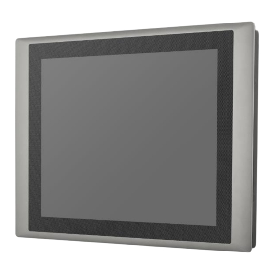
Page 50: Cv-W115Fh/P1301 Series
1.2.7 CV-W115FH/P1301 Series Model Name CV-W115FHR CV-W115FHC Display • 15.6" (16:9) LCD Size • Max. Resolution 1920 x 1080 (Full HD) • 350 Brightness (cd/m2) • Contrast Ratio 800 : 1 • 16.7M LCD Color • Pixel Pitch(mm) 0.17925 (H) x 0.17925 (V) •... - Page 51 Model Name P1301 System • Onboard Intel® Alder Lake-N Series Processor: - Intel® Core™ i3-N305 8 Cores Up to 3.80 GHz, TDP 15W Processor - Intel® Processor N97 4 Cores Up to 3.60 GHz, TDP 12W - Intel Atom® x7425E 4 Cores Up to 3.40 GHz, TDP 12W •...
- Page 52 • 1x Reset Button Reset Button • Support 0.2sec Instant Reboot Technology Instant Reboot • Software Programmable Supports 256 Levels System Reset Watchdog Timer • LCD On/Off, Brightness Up, Brightness Down OSD Button • AMP 2W + 2W Internal Speaker •...
- Page 53 • UL, cUL, CB, IEC, EN62368-1 Safety * Product Specifications and features are for reference only and are subject to change without prior notice. For more information, please refer to the latest product datasheet from Cincoze's website. CV-100/P1301 Series | User Manual...
- Page 54 Dimensions CV-W115FH/P1301 unit: mm CV-100/P1301 Series | User Manual...
-
Page 55: Cv-117/P1301 Series
1.2.8 CV-117/P1301 Series Model Name CV-117R CV-117C CV-117G Display • 17" (5:4) LCD Size • Max. Resolution 1280 x 1024 • 350 Brightness (cd/m2) • Contrast Ratio 800 : 1 • 16.2M LCD Color • Pixel Pitch(mm) 0.264 (H) x 0.264 (V) •... - Page 56 • EN/IEC 61000-4-11 Voltage Dips & Voltage Interruptions: 0.5 cycles at 50 Hz • UL, cUL, CB, IEC, EN 62368-1 Safety Model Name P1301 System • Onboard Intel® Alder Lake-N Series Processor: - Intel® Core™ i3-N305 8 Cores Up to 3.80 GHz, TDP 15W Processor - Intel®...
- Page 57 • 1x CFM Interface for optional PoE Module Expansion Interface Other Function • 1x Clear CMOS Switch Clear CMOS Switch • 1x Reset Button Reset Button • Support 0.2sec Instant Reboot Technology Instant Reboot • Software Programmable Supports 256 Levels System Reset Watchdog Timer •...
- Page 58 • UL, cUL, CB, IEC, EN62368-1 Safety * Product Specifications and features are for reference only and are subject to change without prior notice. For more information, please refer to the latest product datasheet from Cincoze's website. CV-100/P1301 Series | User Manual...
- Page 59 Dimensions CV-117/P1301 unit: mm CV-100/P1301 Series | User Manual...
-
Page 60: Cv-119/P1301 Series
1.2.9 CV-119/P1301 Series Model Name CV-119R CV-119C CV-119G Display • 19" (5:4) LCD Size • Max. Resolution 1280 x 1024 • 350 Brightness (cd/m2) • Contrast Ratio 1000 : 1 • 16.7M LCD Color • Pixel Pitch(mm) 0.294 (H) x 0.294 (V) •... - Page 61 Model Name P1301 System • Onboard Intel® Alder Lake-N Series Processor: - Intel® Core™ i3-N305 8 Cores Up to 3.80 GHz, TDP 15W Processor - Intel® Processor N97 4 Cores Up to 3.60 GHz, TDP 12W - Intel Atom® x7425E 4 Cores Up to 3.40 GHz, TDP 12W •...
- Page 62 • 1x Reset Button Reset Button • Support 0.2sec Instant Reboot Technology Instant Reboot • Software Programmable Supports 256 Levels System Reset Watchdog Timer • LCD On/Off, Brightness Up, Brightness Down OSD Button • AMP 2W + 2W Internal Speaker •...
- Page 63 • UL, cUL, CB, IEC, EN62368-1 Safety * Product Specifications and features are for reference only and are subject to change without prior notice. For more information, please refer to the latest product datasheet from Cincoze's website. CV-100/P1301 Series | User Manual...
- Page 64 Dimensions CV-119/P1301 unit: mm CV-100/P1301 Series | User Manual...
-
Page 65: Cv-W121/P1301 Series
1.2.10 CV-W121/P1301 Series Model Name CV-W121R CV-W121C CV-W121G Display • 21.5" (16:9) LCD Size • Max. Resolution 1920 x 1080 • 350 Brightness (cd/m2) • Contrast Ratio 5000 : 1 • 16.7M LCD Color • Pixel Pitch(mm) 0.24825 (H) x 0.24825 (V) •... - Page 66 Model Name P1301 System • Onboard Intel® Alder Lake-N Series Processor: - Intel® Core™ i3-N305 8 Cores Up to 3.80 GHz, TDP 15W Processor - Intel® Processor N97 4 Cores Up to 3.60 GHz, TDP 12W - Intel Atom® x7425E 4 Cores Up to 3.40 GHz, TDP 12W •...
- Page 67 • 1x Reset Button Reset Button • Support 0.2sec Instant Reboot Technology Instant Reboot • Software Programmable Supports 256 Levels System Reset Watchdog Timer • LCD On/Off, Brightness Up, Brightness Down OSD Button • AMP 2W + 2W Internal Speaker •...
- Page 68 • UL, cUL, CB, IEC, EN62368-1 Safety * Product Specifications and features are for reference only and are subject to change without prior notice. For more information, please refer to the latest product datasheet from Cincoze's website. CV-100/P1301 Series | User Manual...
- Page 69 Dimensions CV-W121/P1301 unit: mm CV-100/P1301 Series | User Manual...
-
Page 70: Cv-W124/P1301 Series
1.2.11 CV-W124/P1301 Series Model Name CV-W124R CV-W124C CV-W124G Display • 24" (16:9) LCD Size • Max. Resolution 1920 x 1080 • 350 Brightness (cd/m2) • Contrast Ratio 5000 : 1 • 16.7M LCD Color • Pixel Pitch(mm) 0.27675 (H) x 0.27675 (V) •... - Page 71 • EN/IEC 61000-4-5 Surges: AC Power: 2 kV; Signal: 1 kV • EN/IEC 61000-4-6 CS: 3V • EN/IEC 61000-4-8 PFMF: 50 Hz, 1A/m • EN/IEC 61000-4-11 Voltage Dips & Voltage Interruptions: 0.5 cycles at 50 Hz • Safety UL, cUL, CB, IEC, EN 62368-1 Model Name P1301 System...
- Page 72 • 1x M.2 Key E Type 2230 Socket for Wireless/Intel CNVi Module Expansion M.2 Key E Socket • 1x Front Accessible SIM Socket SIM Socket • 1x CFM Interface for optional IGN Module Expansion CFM (Control Function Module) • 1x CFM Interface for optional PoE Module Expansion Interface Other Function •...
- Page 73 • UL, cUL, CB, IEC, EN62368-1 Safety * Product Specifications and features are for reference only and are subject to change without prior notice. For more information, please refer to the latest product datasheet from Cincoze's website. CV-100/P1301 Series | User Manual...
- Page 74 Dimensions CV-W124/P1301 unit: mm CV-100/P1301 Series | User Manual...
-
Page 75: External Layout
1.3 External Layout 1.3.1 Front 1.3.2 Rear CV-100/P1301 Series | User Manual... -
Page 76: Left
1.3.3 Left 1.3.4 Right CV-100/P1301 Series | User Manual... -
Page 77: Chapter 2 Introduction To Switches & Connectors
Chapter 2 Introduction to Switches & Connectors CV-100/P1301 Series | User Manual... -
Page 78: Location Of Switches And Connectors
2.1 Location of Switches and Connectors 2.1.1 Top View 2.1.2 Bottom View CV-100/P1301 Series | User Manual... -
Page 79: Switches And Connectors Definition
2.2 Switches and Connectors Definition Location Definition AT_ATX1 AT / ATX Power Mode Switch BAT1 RTC Battery Holder BL_DN1 Backlight Decrease Button BL_PWR1 Backlight Power on/off Button BL_UP1 Backlight Increase Button CAP_PH1 CAP Board to Board Connector CLR_CMOS1 Clear CMOS Switch M.2 Key B Socket (Support PCIE/USB3.0/ SATA interface) COM1_1 / COM2_1 DB9 Connectors, support RS232 / RS422 / RS485... -
Page 80: Definition Of Switches
2.3 Definition of Switches AT_ATX1: AT / ATX Power Mode Switch Switch Definition Left AT Power Mode Right ATX Power Mode (Default) BL_DN1: Backlight Brightness Decrease Switch Definition Push Backlight Decrease BL_PWR1: Backlight Power on / off Switch Definition Push Backlight Power on / off switching BL_UP1: Backlight Brightness Increase Switch... - Page 81 PWR_SW1: System Power Button Switch Definition Push Power up the System RESET1: Reset Button Switch Definition Push Reset System SW1: Super CAP SW Location Function DIP1 DIP2 Super CAP Enabled ON (Default) ON (Default) Super CAP Disabled SW3: Power Select for COM1/COM2 Location Function DIP1...
-
Page 82: Definition Of Connectors
2.4 Definition of Connectors CN1 : M.2 Key B Socket (Support PCIE/USB3.0/ SATA interface) Pin No. PIN Name Pin No. PIN Name Pin No. PIN Name CFG3 100M_CLKN +3.3V M.2_BT_PCMFRM WAKE# PCIE2_RXN/USB3 RXN 100M_CLKP +3.3V USIM_RESET PCIE2_RXP/USB3 RXP PULL-UP USIM_CLK USB2- PULL-UP USIM_DATA... - Page 83 M2E_1 : M.2 Key E Socket (Support PCIE / CNVi Module) Pin No. Pin No. PIN Name Pin name +3.3V USB_D+ +3.3V USB_D‐ PCM_CLK WGR_D1N PCM_SYNC/LPC_RSTN WGR_D1P PCM_IN PCM_OUT WGR_D0N WGR_D0P UART_WAKE# WGR_CLKN UART_RX/BRI_RSP WGR_CLKP UARTX/RGI_DT UART_CTS/RGI_RSP PETP0 UART_RTS/BRI_DT PETN0 PERP0 PERN0 REFCLKP0...
- Page 84 REF_CLK WT_D0N WT_D0P SUSCLK +3.3V WTCLKN +3.3V WTCLK +3.3V COM1_1 / COM2_1: RS232 / RS422 / RS485 Connector Connector Type: 9-pin D-Sub RS232 RS422 / 485 Full RS485 Half Definition Duplex Definition Duplex Definition DATA - DATA + DC_IN1: DC 9-48V Power Input Connector, with Power Ignition Connector Connector Type: Terminal Block 1x3 3-pin, 5.0mm pitch Definition +9-48VIN...
- Page 85 DIO1: Digital 4IN / 4OUT Connector Connector Type: Terminal Block 1X10 10-pin, 3.5mm pitch Definition Definition XCOM+ (DC INPUT) XCOM- (GND) RMT_BNT1: Remote Power Button / Remote LED Connector Remote Power LED connector can connect an external LED indicator up to 10mA. Connector Type: Terminal Block 1X4 4-pin, 3.5mm pitch 1 2 3 4 Definition...
-
Page 86: Optional Module Pin Definition & Settings
2.5 Optional Module Pin Definition & Settings 2.5.1 CFM-IGN101 Module SW2 (on the module):IGN Module Timing Setting Switch Set shutdown delay timer when ACC is turned off Pin 1 Pin 2 Pin 3 Pin 4 Definition 0 second 1 minute ON (IGN 5 minutes Enabled) -
Page 87: Chapter 3 System Setup
Chapter 3 System Setup CV-100/P1301 Series | User Manual... -
Page 88: Removing Top Cover
3.1 Removing Top Cover In order to prevent electric shock or system damage, must turn off power and disconnect the unit from power source before removing the chassis cover. (Afin d'éviter tout risque d'électrocution ou d'endommagement du système, vous devez couper l'alimentation et débrancher l'appareil de la source d'alimentation avant de retirer le couvercle du châssis.) Step 1. -
Page 89: Installing So-Dimm Memory
3.2 Installing SO-DIMM Memory Step 1. Locate the SO-DIMM sockets. Step 2. Tilt the SO-DIMM module at a 45-degree angle and insert it to SO-DIMM socket until the gold-pated connector of module contacted firmly with the socket. 45° Step 3. Press the modules down until it’s fixed firmly by the two locking latches on each side. CV-100/P1301 Series | User Manual... -
Page 90: Installing M.2 Key B Card
3.3 Installing M.2 Key B Card 3.3.1 M.2 Key B type 3052 Step 1. Locate the M.2 Key B slot. Step 2. Insert the M.2 Key B card at a 45-degree angle and insert it to the slot until the gold-pated connector of module contacted firmly with the slot. -
Page 91: Key B Type 3042
3.3.2 M.2 Key B type 3042 Step 1. Locate the M.2 Key B slot. Step 2: Align the M.2 Key B Type 3052 to 3042 Adapter Bracket with the corresponding screw hole. Secure the bracket in place and fasten the screw. Step 3. -
Page 92: Installing M.2 Key E Card
Step 4. Press down the module and fasten the screw to secure the module. 3.4 Installing M.2 Key E Card Step 1. Locate the M.2 Key E slot on the system board. Step 2. Tilt the M.2 Key E card at a 45-degree angle and insert it to the socket until the golden finger connector of the card seated firmly. -
Page 93: Installing Antenna(S)
3.5 Installing Antenna(s) Please install a Wireless LAN card before the antenna installation. Step 1. Remove the antenna hole cover(s) on the front or the side panel. Step 2. Have the antenna jack penetrate through the hole. Step 3. Put on the washer and fasten the nut with the antenna jack. CV-100/P1301 Series | User Manual... - Page 94 Step 4. Assemble the antenna and antenna jack together. Step 5. Attach the RF connector at another end of cable onto the module. CV-100/P1301 Series | User Manual...
-
Page 95: Installing Cpu Thermal Pad
3.6 Installing CPU Thermal Pad Step 1. Remove the protective films of the Thermal Pad’s both sides and then place the thermal pad on the CPU heatsink. Before assembling the system’s chassis cover, please make sure the protective film on the Thermal Pad has been removed! (Avant d'assembler le couvercle du châssis du système, assurez-vous que le film protecteur sur le coussin thermique a été... -
Page 96: Installing Top Cover
3.7 Installing Top Cover Step 1. Put on the cover. Step2. Fasten the 8 screws to fix the cover. CV-100/P1301 Series | User Manual... -
Page 97: Installing Sata Hard Drive
3.8 Installing SATA Hard Drive Step 1. Loosen the 2 screws on the front panel to remove the cover plate. Step 2. Loosen the screw on the HDD bracket. Step 3. Pull out the HDD bracket. Step 4. Make the bottom side of the HDD face up, place the HDD bracket on it. Ensure the direction of bracket is correct and use 4 provided screws to assemble HDD and HDD bracket together. - Page 98 Step 5. Align the HDD bracket with the entrance of HDD bay. And insert the HDD bracket until the connector of HDD contact the SATA connector firmly. Step 6. Fasten the screw on the HDD bracket. Step 7. Fasten the 2 screws on the front panel. CV-100/P1301 Series | User Manual...
-
Page 99: Installing Sim Card
3.9 Installing SIM Card Step 1. Loosen the 2 screws on front panel to remove cover plate. Step 2. SIM card slot is at the front panel of the system. Step 3. Insert the SIM card until you hear a click sound; that indicates the installation is complete. CV-100/P1301 Series | User Manual... -
Page 100: Installing Cfm Modules
3.10 Installing CFM Modules Please refer to chapter 3.1 to remove the top cover of the P1301 system first. 3.10.1 CFM-IGN101 Step 1. Locate the IGN connector on system motherboard as indicated. Step 2. Insert CFM-IGN module vertically to the female connector on the system’s mainboard, and fasten the 2 screws to fix it. -
Page 101: Cfm-Poe02
3.10.2 CFM-PoE02 Step 1. Locate the PoE connector on system motherboard as indicated. Step 2. Insert the female connector of CFM-PoE module to the male connector on system motherboard. Step 3. Turn over the heatsink and paste the thermal pad onto the marked by red squares. Before putting on the thermal block (in the next step), please make sure the protective film on the Thermal Pad has been removed! (Avant de mettre le bloc thermique (à... - Page 102 Step 4. Paste the heatsink onto the CFM-PoE module carefully and fasten 2 screws to fix it. Step 5. Paste the thermal pads onto the heatsink and coil carefully. Before assembling the system’s chassis cover, please make sure the protective film on the Thermal Pad has been removed! (Avant d'assembler le couvercle du châssis du système, assurez-vous que le film protecteur sur le coussin thermique a été...
-
Page 103: Disassembling The Cv Display Module
Step 1. Remove the 6 screws on the display module and then disconnect the module. 3.12 Installing Panel Mount Step 1. Accessories provided by Cincoze are as below. (Please note that the quantity of mounting kits varies with the size of the display module, please refer to the datasheet for the actual quantity) - Page 104 Step 2. All mounting kits displayed are to be inserted into holes. Step 3. Installation preparation and steps. CV-100/P1301 Series | User Manual...
- Page 105 CV-100/P1301 Series | User Manual...
-
Page 106: Installing Vesa Mount
Step 4. Apply all mount kits to the rest of holes. And you have completed the panel mount installation, as shown below. 3.13 Installing VESA Mount The following picture indicates VESA mounting hole pattern on the P1301, which is compliant with VESA mounting standard. -
Page 107: Installing Rack Mount
3.14 Installing Rack Mount Step 1. Locate and align the screw holes on the PC module with those on the rack mount base. Fasten 8 M4x6 screws securely for a stable connection. Rack Mount Base Step 2. Locate the mounting holes on the rack mount brackets, as illustrated in the pictures below, depicting three different sets of screw holes for mounting the 8.4”... - Page 108 Step 3. Assemble the brackets and the rack mount base by securing 4 M5x6 screws on each side. For 8.4” ~ 17” Panel PC Side View Side View Bottom View For 19” ~ 24” Panel PC Side View Side View Bottom View Step 4.
- Page 109 Step 5. And then assemble two rack mount brackets and the rack by fastening 4 M5x12 screws, flat washers and hex nuts at each side. Rack For 8.4” ~ 17” Panel PC For 19” ~ 24” Panel PC CV-100/P1301 Series | User Manual...
-
Page 110: Chapter 4 Bios Setup
Chapter 4 BIOS Setup CV-100/P1301 Series | User Manual... -
Page 111: Bios Introduction
4.1 BIOS Introduction The BIOS (Basic Input/ Output System) is a program located on a Flash Memory on the motherboard. When you start the computer, the BIOS program will gain control. The BIOS first operates an auto-diagnostic test called POST (power on self-test) for all the necessary hardware, it detects the entire hardware device and configures the parameters of the hardware synchronization. -
Page 112: Main Setup
4.2 Main Setup Press <Del> to enter BIOS CMOS Setup Utility, the Main Menu (as shown below) will appears on the screen. Use arrow keys to move among the items and press <Enter> to accept or enter a sub-menu. ◼ System Date Set the date. -
Page 113: Advanced Setup
4.3 Advanced Setup This section allows you to configure and improve your system and allows you to set up some system features according to your preference. 4.3.1 CPU Configuration ◼ Intel (VMX) Virtualization Technology [Enabled] Enables or disables Intel Virtualization Technology. Virtualization enhanced by Intel Virtualization Technology will allow a platform to run multiple operating systems and applications in independent partitions. -
Page 114: Sata Configuration
4.3.2 SATA Configuration ◼ SATA Controller(s) [Enabled] Enables or disables SATA device. ◼ SATA Mode Selection [AHCI] Allows you to select which mode SATA controller will operates. Configuration options: [AHCI] ❑ Serial ATA Port 0 Port 0 [Enabled] Enables or disables SATA Port 0. ❑... -
Page 115: Trusted Computing Settings
◼ Firmware Update Configuration Configure Management Engine Parameters ❑ Me FW Image Re-Flash [Disabled] Enables or disables ME firmware Image Re-Flash function. 4.3.4 Trusted Computing Settings ◼ Security Device Support [Enabled] Enables or disables Security Device Support function. ◼ SHA256 PCR Bank [Enabled] Enables or disables SHA256 PCR Bank function. - Page 116 Enables or disables SM3_256 PCR Bank function. ◼ Pending Operation [None] Allows you to select which mode Pending Operation will operate. Configuration options: [None], [TPM Clear] ◼ Platform Hierarchy [Enabled] Enables or disables Platform Hierarchy function. ◼ Storage Hierarchy [Enabled] Enables or disables Storage Hierarchy function.
-
Page 117: Acpi Settings
4.3.5 ACPI Settings ◼ Enable Hibernation [Enabled] Enables or disables system ability to hibernate state (OS/S4 state). This option may not be effective with some OS. ◼ ACPI Sleep State [S3 (Suspend to RAM)] Allows users to select the highest Advanced Configuration Power Interface® (ACPI) sleep state that system will enter when suspend button is pressed. - Page 118 ◼ Serial Port 1~2 Configuration. ❑ Serial Port [Enabled] Enables or disables serial port. ❑ Change Settings [Auto] Allows you to change the IO Address & IRQ settings of the specified serial port. ❑ Serial Port Mode [RS232] Allows you to select Serial Port Mode. Configuration options: [RS232] [RS422/RS485 Full Duplex] [RS485 Half Duplex] ◼...
-
Page 119: Hardware Monitor
4.3.7 Hardware Monitor This screen displays the current status of all monitored hardware devices/components such as voltages, temperatures. 4.3.8 S5 RTC Wake Settings ◼ Wake system from S5 [Disabled] Enables or disables wake system from S5 (soft-off state). [Disabled]: Disables wake system from S5. [Fixed Time]: Sets a fixed time (HH:MM:SS) to wake system from S5. -
Page 120: Serial Port Console Redirection
4.3.9 Serial Port Console Redirection ◼ Console Redirection [Disabled] Allow users to enable or disable COM1, COM2, COM3 console redirection function. 4.3.10 USB Configuration ◼ XHCI Hand-off [Enabled] Enables or disables XHCI (USB3.0) hand-off function. Use this feature as a workaround for operating systems without XHCI hand-off support. -
Page 121: Network Stack Configuration
4.3.11 Network Stack Configuration ◼ Network Stack [Disabled] Enables or disables UEFI Network Stack. 4.3.13 CSM Configuration ■ CSM Support [Disabled] Enables or disables compatibility support module. CV-100/P1301 Series | User Manual... -
Page 122: Nvme Configuration
4.3.14 NVMe Configuration The screen allows users to select options for the NVMe configuration, and change the value of the selected option. If there is NVMe Device detected, the options will show as the NVMe Device is found. CV-100/P1301 Series | User Manual... -
Page 123: Chipset Setup
4.4 Chipset Setup This section allows you to configure chipset related settings according to user’s preference. 4.4.1 System Agent (SA) Configuration ◼ Memory Configuration This item displays detailed memory configuration in the system. ◼ VT-d [Enabled] Enables or disables Intel® Virtualization Technology for Directed I/O (VT-d) capability. CV-100/P1301 Series | User Manual... -
Page 124: Pch-Io Configuration
4.4.2 PCH-IO Configuration ◼ PCI Express Configuration ❑ PCI Express Root Port (M2E_1) ◼ PCI Express Root Port [Enabled] Enables or disables PCI Express Root Port. ◼ PCIe Speed [Auto] Allows you to select PCI Express interface speed. Configuration options: [Auto] [Gen1] [Gen2] [Gen3]. ❑... - Page 125 ◼ HD Audio Configuration ◼ HD Audio [Enabled] Enables or disables HD Audio function. ◼ LAN 1 i225 [Enabled] Enables or disables I210 LAN Controller. ◼ LAN 2 i225 [Enabled] Enables or disables I210 LAN Controller. ◼ Wake# event (PCIe) [Enabled] Enables or disables Wake# event (PCIe).
-
Page 126: Security Setup
4.5 Security Setup This section allows users to configure BIOS security settings. ◼ Administrator Password Administrator Password controls access to the BIOS Setup utility. ◼ User Password User Password controls access to the system at boot and to the BIOS Setup utility. ◼... -
Page 127: Boot Setup
4.6 Boot Setup This section allows you to configure Boot settings. ◼ Setup Prompt Timeout [1] Use this item to set number of seconds (1..65535) to wait for setup activation key. ◼ Bootup NumLock State Allows you to set NumLock key to [On] or [Off] state when system boots up. ◼... -
Page 128: Save & Exit
4.7 Save & Exit ◼ Save Changes and Exit This item allows you to exit the system after saving changes. ◼ Discard Changes and Exit This item allows you to exit system setup without saving any changes. ◼ Save Changes and Reset This item allows you to reset the system after saving changes. -
Page 129: Chapter 5 Product Application
Chapter 5 Product Application CV-100/P1301 Series | User Manual... -
Page 130: Where To Download Drivers
5.1 Where to download drivers? Drivers for the CV-100/P1301 Series can be downloaded from the CINCOZE website. 5.2 Where to find the technical documents? The following documents are the most relevant technical references for the CV-100/P1301 Series. All documents can be accessed via the CINCOZE Partner Zone: •... - Page 131 Remote Switch Function Manual Wake On LAN Function Manual WDT Function Manual CV-100/P1301 Series | User Manual...
- Page 132 © 2024 Cincoze Co., Ltd. All rights reserved. The Cincoze logo is a registered trademark of Cincoze Co., Ltd. All other logos appearing in this catalog are the intellectual property of the respective company, product, or organization associated with the logo.
Need help?
Do you have a question about the CV-W115FH/P1301 Series and is the answer not in the manual?
Questions and answers