Vulcan-Hart 148L Service Manual
Gas restaurant ranges 90 series and vg series
Hide thumbs
Also See for 148L:
- Installation & operation manual (32 pages) ,
- Replacement parts manual (21 pages) ,
- Installation and operation manual (64 pages)
Table of Contents
Advertisement
GAS RESTAURANT RANGES
90 SERIES AND VG SERIES
MODEL
24L
48L
481L/LC
148L/LC
36L/LC
60L/LC/LCC
160L/LC
260L/LC/LCC
VG24
VG36
VG48
VG60
VG160
VG260
V U L C A N - H A R T C O M P A N Y , P . O . B O X 6 9 6 , L O U I S V I L L E , K Y 4 0 2 0 1 - 0 6 9 6 , TEL. (502) 7 7 8 - 2 7 9 1
FORM 31056 Rev. A (1-99)
ML-52947
ML-52949
ML-52950
ML-52951
ML-52948
ML-52952
ML-52953
ML-52954
ML-114553
ML-114554
ML-114957
ML-114555
ML-114556
ML-114557
Service Manual
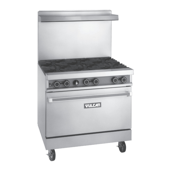
MODEL 36L/VG36
Advertisement
Table of Contents

Related Manuals for Vulcan-Hart 148L


Summary of Contents for Vulcan-Hart 148L
- Page 1 Service Manual GAS RESTAURANT RANGES 90 SERIES AND VG SERIES MODEL ML-52947 ML-52949 481L/LC ML-52950 148L/LC ML-52951 36L/LC ML-52948 60L/LC/LCC ML-52952 160L/LC ML-52953 260L/LC/LCC ML-52954 VG24 ML-114553 VG36 ML-114554 VG48 ML-114957 VG60 ML-114555 VG160 ML-114556 VG260 ML-114557 MODEL 36L/VG36 V U L C A N - H A R T C O M P A N Y , P . O . B O X 6 9 6 , L O U I S V I L L E , K Y 4 0 2 0 1 - 0 6 9 6 , TEL. (502) 7 7 8 - 2 7 9 1...
- Page 2 Qualified service personnel are those who are familiar with Vulcan equipment who have been endorsed by the Vulcan-Hart Corporation. All authorized service personnel are required to be equipped with a complete set of service and parts manuals and stock a minimum amount of parts for Vulcan equipment. — 2 —...
-
Page 3: Important For Your Safety
IMPORTANT FOR YOUR SAFETY THIS MANUAL HAS BEEN PREPARED FOR PERSONNEL QUALIFIED TO INSTALL GAS EQUIPMENT, WHO SHOULD PERFORM THE INITIAL FIELD START-UP AND ADJUSTMENTS OF THE EQUIPMENT COVERED BY THIS MANUAL. POST IN A PROMINENT LOCATION THE INSTRUCTIONS TO BE FOLLOWED IN THE EVENT THE SMELL OF GAS IS DETECTED. -
Page 4: Gas Restaurant Range Models
60L, 60LC, 60LCC, 160L, 160LC, 260L, 260LC, 260LCC, VG60 VG160 VG260 481L, 481LC 148L, 148LC 24L, 36L, 36LC, VG24 VG36 PL-53007 NOTE: Reference to 90 Series Convection Ovens will include only the following models: 36LC, 148LC, 481LC, 60LC, 60LCC, 160LC, 260LC, or 260LCC. -
Page 5: Table Of Contents
SERVICE MANUAL GAS RESTAURANT RANGES INDEX PLEASE KEEP THIS MANUAL FOR FUTURE REFERENCE DESCRIPTION PAGE SERVICE NOTATIONS UNITS MOUNTED ON CASTERS SERVICING SIMPLE CHECKS AND ADJUSTMENTS 7-10 GAS CONNECTIONS 11, 12 TESTING THE GAS SUPPLY SYSTEM ORIFICE SIZE REQUIREMENTS FOR DIFFERENT ELEVATIONS PILOT LIGHTING AND ADJUSTMENTS 13-17 THERMOSTAT ADJUSTMENTS... -
Page 6: Service Notations
1. The procedures outlined in this manual are to be performed only by Vulcan-Hart authorized service representa- tives. 2. An authorized Vulcan-Hart service representative is one who is familiar with Vulcan equipment and who has been endorsed by Vulcan-Hart Company to service the equipment. All authorized service personnel are required to stock a minimum amount of parts and should be equipped with a complete set of wiring diagrams, service and parts manuals covering all Vulcan-Hart equipment. -
Page 7: Units Mounted On Casters
UNITS MOUNTED ON CASTERS Units mounted on casters utilizing a flex hose and quick-disconnect must be installed with a restraining device. The restraining device must be connected at all times. If disconnection of the device is necessary, turn off the gas supply before disconnection. - Page 8 SERVICING SIMPLE CHECKS AND ADJUSTMENTS (Cont.) 2. Oven Door Turnbuckle NOTE: For the 24L and 48L units, refer to procedure outlined under 2A. If the oven door is not closing properly, the door turnbuckle may require adjustment. To adjust the turnbuckle, flip down the lower front kick panel.
- Page 9 SERVICING SIMPLE CHECKS AND ADJUSTMENTS (Cont.) 3. Pilot Flame Height TOOLS REQUIRED: Standard flat blade screwdriver. Top Burners: To adjust pilot flame height of the unit top burners, locate the pilot adjustment screws found on the front manifold pipe. It is not necessary to remove the manifold cover, as adjustment access holes have been provided in the panel.
- Page 10 SERVICING SIMPLE CHECKS AND ADJUSTMENTS (Cont.) 2. With screwdriver, adjust pilot key (located under pilot adjustment cap) to provide the proper size flame. 3. Replace pilot adjustment cap. NOTE: If unit still is not heating correctly, refer to THERMOSTAT ADJUSTMENTS on Page 18. 4.
-
Page 11: Gas Connections
Standard units are equipped with fixed burner orifices which coincide with the proper unit operation elevation. See Orifice Size Requirements for Different Elevations on Page 12. NOTE: Do not attempt to drill out orifice sizes. Obtain proper conversion kit from Vulcan-Hart depot. Install the gas pressure regulator. -
Page 12: Testing The Gas Supply System
GAS CONNECTIONS (Cont.) NOTE: A leak limiter is supplied with every regulator to allow excess gas pressure to escape. Do not obstruct leak limiter on gas pressure regulator as obstruction may cause regulator to malfunction. WARNING: PRIOR TO LIGHTING, CHECK ALL JOINTS IN THE GAS SUPPLY LINE FOR LEAKS. USE SOAP AND WATER SOLUTION. -
Page 13: Pilot Lighting And Adjustments
All adjustment procedures associated with pilot lighting must be performed by an authorized Vulcan-Hart installation or service person. While performing these procedures, do not turn the burner valves “ON” with the burner heads removed. - Page 14 PILOT LIGHTING AND ADJUSTMENTS (Cont.) OPEN TOP BURNERS 1. Turn main gas supply “ON”. 2. Wait 30 seconds and, using a taper, light the open top pilot (Fig. 10). Fig. 10 3. If pilot fails to light, turn main gas supply “OFF”. Wait 5 minutes and repeat the above procedures. 4.
- Page 15 PILOT LIGHTING AND ADJUSTMENTS (Cont.) BROILER/GRIDDLE 1. Turn main gas supply “ON”. 2. Wait 30 seconds and, using a taper, light broiler/griddle pilot (see Fig. 9). 3. If pilot fails to light, turn main gas supply “OFF”. Wait 5 minutes and repeat Steps 1 and 2. 4.
- Page 16 PILOT LIGHTING AND ADJUSTMENTS (Cont.) 2. Light pilot by depressing the reset button located behind the kick panel (Fig. 12). Light pilot and continue to hold reset button in for 1 minute. If pilot fails to light, turn main gas supply “OFF” and wait 5 minutes before repeating Step 2. 3.
- Page 17 4. Disconnect electrical supply cord. OVEN BURNER ADJUSTMENTS NOTE: These procedures should be performed only by a qualified Vulcan-Hart service representative. TOOLS REQUIRED: Standard flat blade screwdriver. All Restaurant Range series units equipped with pressure regulator and fixed orifices have been adjusted at the factory and should require no further adjustments.
-
Page 18: Thermostat Adjustments
THERMOSTAT ADJUSTMENTS NOTE: These procedures should be performed only by a qualified Vulcan-Hart service representative. STANDARD OVEN Although the unit thermostats are factory positioned to their proper setting, it is not unusual for the thermostat to be knocked out of adjustment during shipment. If the oven or griddle heat response seems to be lacking after burner air shutter adjustments have been checked, perform the following adjustments. - Page 19 THERMOSTAT ADJUSTMENTS (Cont.) 3. Light the burner. Turn the dial to the highest set temperature. 4. After 10 minutes, turn the dial clockwise to the point slightly beyond the first mark on the dial (shown by an “X”). 5. Remove the dial and sleeve (Fig. 17). Shown with old style burner knobs.
- Page 20 THERMOSTAT ADJUSTMENTS (Cont.) 3. Allow unit to heat until the burner flame is heard cutting “OFF”. Wait about 10 minutes until the burner flame has cycled “ON” and “OFF” several times. Then compare the test instrument reading with the dial setting. If the reading is within 15 F (-9.44 C) of the dial setting, its calibration is correct.
- Page 21 THERMOSTAT ADJUSTMENTS (Cont.) 10. To recalibrate, hold the thermostat dial in place. Insert screwdriver into dial shaft to engage the calibration stem adjustment screw (Fig. 20). Push inward (do not turn stem). Fig. 20 11. While holding stem calibration screw in place, turn thermostat dial until it is set on the actual temperature shown by the testing device (Fig.
-
Page 22: Thermostat Adjustments
THERMOSTAT ADJUSTMENTS (Cont.) ® CONVECTION (SNORKEL ) OVEN (90 Series Only) TOOLS REQUIRED: Thermometer (not of bi-metal or mercury type), standard flat blade screwdriver. WARNING: DO NOT USE BI-METAL OR MERCURY THERMOMETERS WHEN TESTING FOOD EQUIPMENT OR PRODUCTS. CHEMICALS WITHIN THESE INSTRUMENTS MAY BE TOXIC IF EXPOSED TO FOOD. 1. -
Page 23: Regulator Check, Adjustment, Installation
REGULATOR CHECK, ADJUSTMENT, INSTALLATION REGULATOR CHECK A regulator is installed on each range. When servicing this equipment for possible gas pressure problems, the following visual checks should be made first. Make sure the regulator has been installed at the rear of the unit with arrow pointing in the horizontal position in the direction of gas flow. - Page 24 REGULATOR CHECK, ADJUSTMENT, INSTALLATION (Cont.) 2. With only two open top burners “ON”, note the manometer reading. The reading should be 3.7" Water Column for natural gas units and 10.0" Water Column for propane gas units. If readings taken are lower, check the incoming line pressure.
-
Page 25: Regulator Check, Adjustment, Installation
REGULATOR CHECK, ADJUSTMENT, INSTALLATION (Cont.) 1. Connect the manometer to the pressure tap provided on the rear manifold pipe (see Fig. 23). 2. Check the reading. The reading should be 3.7" Water Column for natural gas and 10.0" Water Column for propane gas. -
Page 26: Standard Oven & Griddle Thermostat Replacement
STANDARD OVEN & GRIDDLE THERMOSTAT REPLACEMENT STANDARD OVEN AND GRIDDLE THERMOSTAT CHECKS AND CALIBRATION Refer to THERMOSTAT ADJUSTMENTS on Page 18 of this manual for the procedures for checking and calibrating the thermostat for the standard oven and griddle. STANDARD OVEN AND GRIDDLE THERMOSTAT REPLACEMENT TOOLS REQUIRED: Pipe wrench, 6"... - Page 27 STANDARD OVEN & GRIDDLE THERMOSTAT REPLACEMENT (Cont.) 4. From inside the oven, straighten the capillary lead. From the opening in the oven top section, pull the capillary out of the oven cavity (Fig. 30). Fig. 30 5. Remove the top section burner valve knobs. 6.
- Page 28 STANDARD OVEN & GRIDDLE THERMOSTAT REPLACEMENT (Cont.) 9. Unscrew the thermostat from the manifold pipe (Figs. 33, 34, & 35). Fig. 34 Fig. 33 Fig. 35 10. Replace thermostat mounting block. Place pipe dope on the threaded end of the new thermostat mounting block to be installed onto the unit.
-
Page 29: Convection Oven Thermostat Replacement
CONVECTION OVEN THERMOSTAT REPLACEMENT ® CONVECTION (SNORKEL ) OVEN THERMOSTAT CHECK AND CALIBRATION (90 Series Only) Refer to the THERMOSTAT ADJUSTMENTS section of this manual for the procedures for checking and calibrating the thermostat for the convection oven (see Page 22). CONVECTION (SNORKEL ®... -
Page 30: Standard Oven Pilot Safety Valve Check, Replacement
If the unit pilot is “ON” but the unit is not heating, check the gas flow from the thermostat to the safety valve, using a flow meter (Fig. 36). (Flow meter kits are available from Vulcan-Hart Service Parts Depots under Part No. 495.) FOR PROPER USAGE OF FLOW METER, REFER TO THE MANUFACTURER’S INSTRUCTIONS PROVIDED IN THE... - Page 31 STANDARD OVEN PILOT SAFETY VALVE CHECK, REPLACEMENT (Cont.) Fig. 37 5. If the millivolt reading is below 5 MV, replace the thermocouple. 6. If the MV reading is within tolerance, the safety valve should be replaced. SAFETY VALVE REPLACEMENT PROCEDURES TOOLS REQUIRED: "...
-
Page 32: Standard Oven Pilot Safety Valve Check, Replacement
STANDARD OVEN PILOT SAFETY VALVE CHECK, REPLACEMENT (Cont.) 3. Disconnect right- and left-hand pilot gas tubing from the safety valve (Fig. 39). Fig. 39 4. Disconnect right- and left-hand burner gas tubing from the safety valve (Fig. 40). Fig. 40 5. -
Page 33: Oven Pilot Check, Replacement
OVEN PILOT CHECK, REPLACEMENT OVEN PILOT CHECK If all other systems have been checked and pilot will not stay lit, replacement of the pilot may be necessary. OVEN PILOT REPLACEMENT TOOLS REQUIRED: " socket, socket driver, " and " open end wrenchs. 1. -
Page 34: Thermocouple Check, Replacement
THERMOCOUPLE CHECK, REPLACEMENT THERMOCOUPLE CHECK 1. Fold lower kick panel down. 2. Perform pilot lighting procedures (see Page 13). 3. If unit will not stay lit, using a volt meter, check the millivolt reading from the valve thermocouple connection while holding pilot button in the “ON”... -
Page 35: Oven Burner Nozzle And Orifice Check, Replacement
BTU rating with flow meter. (Flow meter kits are available from Vulcan-Hart Service Parts Depots under Part No. 495.) FOR PROPER USAGE OF FLOW METER, REFER TO THE MANUFACTURER’S INSTRUCTIONS PROVIDED IN THE FLOW METER KIT. -
Page 36: Oven Burner Check, Replacement
OVEN BURNER CHECK, REPLACEMENT OVEN BURNER CHECK If the oven burner is not properly firing and all other systems have been checked, the oven burner may need to be cleaned or replaced. OVEN BURNER REPLACEMENT TOOLS REQUIRED: " socket and socket driver. 1. -
Page 37: Top Section Pilot Check, Replacement
TOP SECTION PILOT CHECK, REPLACEMENT TOP SECTION PILOT CHECK If all other systems have been checked and pilot will not stay lit, cleaning or replacement of pilot may be necessary. TOP SECTION PILOT REPLACEMENT TOOLS REQUIRED: " open end wrench. 1. -
Page 38: Top Section Burner Valve And Nozzle Check, Replacement
TOP SECTION BURNER VALVE AND NOZZLE CHECK, REPLACEMENT TOP SECTION BURNER VALVE CHECK After a long period of use on the range, the top section burner valve can show signs of wear. Check valve for gas leakage and sloppy valve control. Check also for valve nozzle blockage or damage. TOP SECTION BURNER VALVE AND NOZZLE REPLACEMENT TOOLS REQUIRED: "... - Page 39 CONVECTION OVEN MOTOR AND DOOR SWITCH CHECK, REPLACEMENT (Cont.) Fig. 47 Fig. 48 3. If a short-handled screwdriver is not available, remove (2) screws securing micro switch housing to unit (Fig. 48). This will allow convenient access to the switch in order to use a standard size screwdriver. 4.
- Page 40 CONVECTION OVEN MOTOR AND DOOR SWITCH CHECK, REPLACEMENT (Cont.) 5. Using a volt meter, check the voltage reading between the normally open and common contacts of the micro switch (Fig. 50) under the following conditions: NOTE: Volt meter reading below assumes a line voltage of 115 volts. If the unit under test is operating on a different line voltage (i.e., 220 volts), use that value in place of 115 volts.
- Page 41 CONVECTION OVEN MOTOR AND DOOR SWITCH CHECK, REPLACEMENT (Cont.) Condition II With the micro switch activated (the switch must be manually activated by pushing on the actuator arm) (Fig. 51), the volt meter should read 0 volts with the motor running. Fig.
- Page 42 CONVECTION OVEN MOTOR AND DOOR SWITCH CHECK, REPLACEMENT (Cont.) 3. Disengage (2) screws and (2) nuts from micro switch housing to access switch (Fig. 52). Fig. 52 4. Remove wire connectors while observing their locations for reference when reassembling new switch. 5.
- Page 43 CONVECTION OVEN MOTOR AND DOOR SWITCH CHECK, REPLACEMENT (Cont.) Fig. 53 5. To easily access fan rotor and motor, remove snorkel tube from oven cavity. 6. From inside the oven cavity, remove (4) -20 hex head nuts from the fan wheel cover located on the rear wall of the oven cavity (Fig.
- Page 44 CONVECTION OVEN MOTOR AND DOOR SWITCH CHECK, REPLACEMENT (Cont.) 7. Remove fan wheel cover. 8. Remove (4) -20 hex head nuts securing motor mount plate to rear oven cavity (Fig. 55). Fig. 56 Fig. 55 9. Pull motor assembly forward through oven cavity and away from rear cavity wall (Fig. 56). 10.
- Page 45 CONVECTION OVEN MOTOR AND DOOR SWITCH CHECK, REPLACEMENT (Cont.) Fig. 59 12. If the replacement motor does not include the fan rotor wheel, remove wheel from old motor for use with new motor. To remove fan wheel, loosen (2) large stud-type nuts on rotor hub, using a "...
-
Page 46: Solenoid Check
SOLENOID CHECK If the unit pilot is lit but the burners are not receiving gas, the solenoid may be malfunctioning. First verify that the following conditions are true: With oven door closed, turn power switch to the “ON” position. The power light should now be “ON” and the fan motor should be running. -
Page 47: Centrifulgal Switch Check
CENTRIFUGAL SWITCH CHECK To check the centrifugal switch, the motor must be accessed by either of the following means: 1. Disconnect and pull unit from main gas supply and into an accessible work area. 2. Leave unit in place and remove motor from inside the oven cavity (refer to MOTOR REPLACEMENT section, Page 42). -
Page 48: Removal Of Convection Oven Solenoid
CENTRIFUGAL SWITCH CHECK (Cont.) Fig. 65 Using a volt meter, measure the voltage (110-120 volts) between Wire #23 and ground, and Wire #22 and ground. If voltage is present, or if only one wire (#22) has voltage, the centrifugal switch in the motor is bad. The entire motor must be replaced (see Fig. - Page 49 REMOVAL OF CONVECTION OVEN SOLENOID (Cont.) Fig. 66 Fig. 67 Fig. 68 — 49 —...
- Page 50 REMOVAL OF CONVECTION OVEN SOLENOID (Cont.) Disconnect pilot tubing at tee fitting (Fig. 69). Fig. 70 Fig. 69 4. Disconnect pilot tubing at safety valve (Fig. 70). 5. Disconnect solenoid wire leads (Fig. 71). Fig. 71 Fig. 72 6. Disengage safety valve assembly from the manifold area (Fig. 72). —...
-
Page 51: Removal Of Convection Oven Solenoid
REMOVAL OF CONVECTION OVEN SOLENOID (Cont.) 7. Disengage solenoid and safety valve and remove old solenoid from the safety valve (Fig. 73). Fig. 73 8. Install new solenoid by reversing steps 1 through 7. — 51 —... - Page 52 – NOTES – FORM 31056 Rev. A (1-99) PRINTED IN U.S.A. — 52 —...
Need help?
Do you have a question about the 148L and is the answer not in the manual?
Questions and answers