ZTE MC801A Manual
- Quick start manual (97 pages) ,
- After-sales service manual (38 pages) ,
- Getting started (25 pages)
Advertisement
Product Summary
 Attention
Before performing any maintenance to the MC801A device, you need to verify that the MC801A is in a secure network.
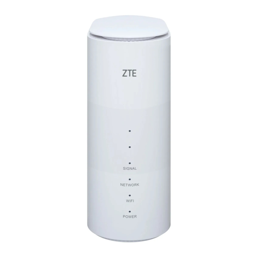
Product Overview

NOTE:
The picture is for reference only. The actual product may be different.
Standard Configuration
| No. | Name | Quantity |
| 1 | MC801A 5G router | 1 |
| 2 | LAN cable | 1 |
| 3 | Power adapter | 1 |
| 4 | Quick start guide | 1 |
Specifications
| Category | Parameter | Specification |
| Physical parameters | Dimensions (Height × Width × Depth) | 182 mm × 124 mm × 70 mm |
| Weight | About 592 g | |
| Frequency bands | 5G NR: sub 6 n40/41/78 FDD-LTE: B1/3/8/20/28 TDD-LTE: B40/41 (2540~2640 MHz) WCDMA: band 1/8 | |
| Technical parameters | Chipsets | SDX55, QCA6391+QCA8337 |
| Storage | 512 MB + 512 MB | |
| Interfaces | RJ45*2, RJ11*1, USB Type-C*1 | |
| Wi-Fi | 802.11 b/g/n/a/ac/ax, 2*2 MIMO for both 2.4 G & 5 G | |
| Max. connected Wi-Fi clients | 30 | |
| Power supply | 12 V/1.5 A |
Function Test
NFF Test
| Test Flow Chart | Test Item | Test Method and Requirements | Test device |
 |
|
| None |
|
| Test card | |
|
| Test card Computer | |
| Use a mobile phone to connect to the Wi-Fi network of MC801A. Check whether the phone can be connected and whether the Internet can be accessed. | Test card Mobile phone | |
| Summary | Perform steps 1 to 4.
| ||
NOTE:
For the test items that are not included in steps 1 to 4, refer to the user manual of MC801A.
Test Web UI
- Connect to MC801A by either of the following ways:
- „ Connecting through LAN cable
Connect the LAN1 port or the LAN2 port of MC801A to the computer with the LAN cable.
NOTE:
You need to set the IP address as Obtain an IP address automatically. Or, you need to set the IP address as 192.168.0.x (x: 2~255) manually. - „ Connecting through Wi-Fi
- Enable the Wi-Fi function on your computer, mobile phone or tablet.
- Select the Wi-Fi hotspot name of MC801A (SSID).
- Type the Wi-Fi password to connect to MC801A.
NOTE:
The default Wi-Fi SSID and password can be found on the bottom of MC801A.
- „ Connecting through LAN cable
- Open the web UI.
- Open the browser and visit the address 192.168.0.1 on the client to open the web UI.
- Type the management password to log in to the web UI.
NOTE:
Check the default management password on the bottom of the device.
- Confirm each function is available, including Internet connection, settings, etc.
NOTE:
A valid nano-SIM card is needed to access the Internet.
Software Download
Preparations
- USB Type-C cable
![]()
- Service software
Type Name/Version Description Driver AS_PCDrvSetupV1.0.0B03 The software versions are for reference only. Please use the latest versions for the software download. Download platform ZTSUFV1.0.1B10 Plug-in SUF_DL_MC801AV1.00.00 Software MC801AV1.0.0B01

Install Driver
- Unzip the driver package AS_PCDrvSetupV1.0.0B03.zip.
- Find and double-click ZTEDrvSetup.exe to start the installation.
- Wait until the installation is completed and click Finish.
![]()

Install Download Platform
- Unzip the package of the download platform and double-click the program icon Setup.exe to start the installation.
- Select the installation language and click OK.

- Click Next.

- Accept the terms of the license agreement and click Next.

- Type the User Name and Company Name and click Next.

- Select the installation directory and click Next.

- Click Install.

- When the installation is completed, click Finish.


Install Plug-in
- Unzip the plug-in package and double-click SUF_DL_MC801AV1.00.00.zas to start the installation.
- Click Install to import the plug-in to the download platform.

- When the installation is completed, click Yes to run the download platform.


The main interface of the download platform is as below.

Download Software
- Unzip and software package.
- Open the download platform and click SW PATH to select 3.Download_File in the software package as the software directory.

- Connect MC801A to a power source and to the computer via USB. Wait until the device is identified by the download platform and click the start button to start the download.

- Wait for the download to finish, as indicated on the progress bar.

- After the download is finished, restart MC801A.


Disassembly
Disassembly Tools

| No. | Name |
| 1 | Anti-electrostatic gloves |
| 2 | Anti-electrostatic wrist strap |
| 3 | Tweezers |
| 4 | Screwdriver |
| 5 | Housing disassembly tool |
NOTE:
In addition to the commonly used tools above, you need to prepare a plastic rod.
Exploded View

Disassembly Steps
The device for disassembly demonstration is for reference only. It might not be completely identical with yours.
- Remove the top cover.

- Remove the 4 screws from the top of the front cover assembly.

- Separate the foot pad from the bottom of the device.

- Remove the 6 screws from the bottom of the lower cover.

- Remove the lower cover.

- Remove the decorative interface plate.
NOTE:
Use a plastic crowbar. Using a metal crowbar may scratch the interface plate.

- Pull out and remove the mainboard bracket assembly from the bottom of the front cover.

- Remove the 4 screws from the directional antenna 2.

- Remove the 4 screws from the heat sink 2 and remove the heat sink 2.

- Disconnect the RF cable of the directional antenna 2 from the mainboard.

- Disconnect the RF cables from the mainboard and remove the A4, A6, and W2 antennas.

- Unlock and remove main antenna 1 from the mainboard bracket.


- Disconnect the RF cables from the mainboard.

- Remove the A5 and A8 antennas on the other side of the bracket.


- Remove the RF cables from the mainboard.

- From the other side of the bracket, remove the insulating tapes and the W1 and A7 antennas.


- Remove the 6 screws securing the mainboard to the bracket.

- Take the mainboard out of the bracket.

- Disconnect the LED sub-board from the mainboard.

- Remove the conductive cloth on the sub-board and the mainboard.

- Unlock and remove the diversity antenna and the main antenna 2.

- Disconnect the RF cable from the mainboard.

- On the other side, remove the screws securing the directional antenna 1 and remove the antenna.


- Remove the screws from the mainboard and remove the heat sink 1.


Composing

| No. | Name |
| 1 | A8 antenna |
| 2 | A5 antenna |
| 3 | Foot pad |
| 4 | Lower cover |
| 5 | Front cover |
| 6 | Mainboard bracket |
| 7 | Mainboard |
| 8 | Heat sink 2 |
| 9 | Heat sink 1 |
| 10 | Directional antenna 1 |
| 11 | Directional antenna 2 |
| 12 | Main antenna 1 |
| 13 | DIV antenna |
| 14 | Main antenna 2 |
| 15 | LED sub-board |
| 16 | Interface decorative plate |
| 17 | Top cover |
| 18 | W2 antenna |
| 19 | A6 antenna |
| 20 | A4 antenna |
| 21 | W1 antenna |
| 22 | A7 antenna |
Principle and Logic Boards
Principle Block Diagram

Basic Component Distribution
- Mainboard top view

No. Name 1 WPS button 2 External antenna connectors 3 RJ11 interface 4 RJ45 interfaces 5 Ethernet transformer 6 DC power connector 7 USB Type-C jack 8 nano-SIM card slot 9 Bluetooth/Wi-Fi chip - Mainboard bottom view

No. Name 1 Ethernet switch


Troubleshooting
Startup Fault

System Crashes/Automatically Powered Off

Wi-Fi Connection Fault

nano-SIM Card Unidentified

Download Fault

Abnormal Indicators

No Signal

Wi-Fi Module Fault

Contact Us
- Website
You can get product introductions and service support from our terminal website (https://www.ztedevices.com). You can also download product manuals and software and check FAQs. Your online query will be replied within 24 hours. - E-mail
If you have any advice, suggestions, or requirements on our products, please send them to mobile@zte.com.cn. Replies will be given within 2 working days. - Hotline
To learn about the hotline and service time for your country or region, please visit https://www.ztedevices.com/en/support/hotlines.

You can also dial the ZTE Customer Service Hotline for terminals +86-755-26779999 (service time (China): 8:30 - 20:30) to learn more about our technical support for ZTE terminals.
Documents / Resources
References

Download manual
Here you can download full pdf version of manual, it may contain additional safety instructions, warranty information, FCC rules, etc.
Advertisement


Need help?
Do you have a question about the MC801A and is the answer not in the manual?
Questions and answers