FPT CURSOR Series, C13ENTZW, F3HFE615A B001 Manual
- Repair manual (274 pages) ,
- Use and maintenance (31 pages) ,
- Use and maintenance (45 pages)
Advertisement
- 1 INTRODUCTION
- 2 GENERAL INFORMATION
- 3 NAMEPLATES
- 4 USE
-
5
CHECKS AND MAINTENANCE
- 5.1 MAINTENANCE PERSONNEL
- 5.2 ACCIDENT PREVENTION
- 5.3 REFUELLING
- 5.4 FREQUENCIES
- 5.5 GUIDELINES
- 5.6 CHECKS TO BE MADE DURING PERIODS OF USE – HOW TO PROCEED
-
5.7
PERIODIC MAINTENANCE - HOW TO PROCEED
- 5.7.1 Draining the water from the fuel pre-filter
- 5.7.2 Change engine lubricant oil
- 5.7.3 Replacing the engine oil filter
- 5.7.4 Replacement of fuel pre-filter (demonstrative)
- 5.7.5 Fuel filter replacement
- 5.7.6 Change the ancillary belt
- 5.7.7 Check turbocharger connection pipes and wastegate linkage
- 5.7.8 Turbocharger lubricant pipe tightness check
- 5.7.9 Turbocharger gasket seal check
- 5.7.10 Turbocharger blade check
- 5.7.11 Wastegate linkage check
- 5.7.12 Replacing blow-by filter element
- 5.8 UNSCHEDULED MAINTENANCE - HOW TO PROCEED
- 5.9 ENGINE HANDLING
- 5.10 DISPOSAL OF WASTE
- 5.11 SCHEDULED MAINTENANCE FOR THE ATS SYSTEM - HOW TO PROCEED
- 6 LONG PERIOD OF ENGINE INACTIVITY
- 7 ENGINE FAULTS
- 8 BEHAVIOURS IN CASE OF EMERGENCY
- 9 Documents / Resources
INTRODUCTION
Before performing any operation that involves the engine or its equipment, please carefully read the instructions contained in this manual; following these instructions is the best way to guarantee that the engine will run perfectly for a long period of time.
The content of this manual refers only to the standard engine configuration and the illustrations are purely indicative. Some instructions are given by describing the sequence of operations that make it possible to obtain the expected behaviour from the engine and/or its equipment. In some cases they depend on the configuration of the controls and versions of the car in which the engine is installed; for anything that differs from the content of this manual, refer to the indications provided by the Manufacturer of the outfitting or the specific manual.
The following information is current as of the date of publication. The Manufacturer reserves the right to make changes without notice at any moment for technical or commercial reasons as well as due to adaptations of the engine to the laws of various countries. No liability is accepted for errors or omissions.
Remember, the FPT Technical Assistance Network is always at the customer's side with skill and professionalism.
GENERAL INFORMATION
SPARE PARTS
The exclusive use of FPT genuine parts is an indispensable condition for maintaining the engine in its original integral condition. The use of non-original spare parts shall invalidate the warranty and exonerate FPT from all liability for the entire life of the engine.
SAFETY
The purpose of the following information is to focus attention on engine use to prevent damage to people and property deriving from improper or incorrect behaviours.
- The engines must only be used for the purposes declared by the Manufacturer.
- Tampering, modifications and the use of non-original spare parts could adversely affect the proper operation of the engine and its safety during use; changes must not be made to the wiring and the units that equip the engine as well as its connections to external electrical networks.
- Pay attention to the engine's moving parts, those at a high temperature and the circuits with pressurised fluids; its electrical equipment is a source of electrical voltage and currents.
- The exhaust gas emitted by the engine is harmful to health.
- The engine must only be handled with suitable lifting devices andusing the specific eyebolts provided on the engine.
- The engine must not be started and used before satisfying the safety requirements for the generator set in which it is installed and before ensuring compliance of the latter with the standards and local laws.
- The operations required for guaranteeing the best state of use and preservation of the engine must be carried out by personnel with proven experience using instruments considered appropriate by FPT.
Additional safety recommendations can be found in the chapter CHECKS AND MAINTENANCE.
SAFETY WARNING SYMBOLS
You will find these symbols on the following pages; follow the instructions to which they refer, for your own safety and that of your
 Risk of injury: failure to comply with these instructions can result in the risk of serious injury.
 Risk of serious damage to the engine: the partial or total non-observance of these instructions could cause serious damage to the engine and may nullify the guarantee
 General danger: combines the risks of both the signs described above.

Safeguarding the environment: indicates the correct behaviour so that vehicle use is as environmentally friendly as possible.
ENGINE TECHNICAL DATA
The technical code and serial number are specified on the nameplate positioned on different parts of the engine, depending on the model: flywheel case, tappet cover, coolant tank.
C13ENTZW (Tier 4B)
| Code | C13ENTZW |
| Engine family | F3HFE615A*B001 F3HFE615B*B001 F3HFE615C*B001 |
| Cycle | Diesel 4-stroke |
| Number and arrangement of cylinders | 6 in line |
| Bore x stroke | 135 x 150 mm |
| Total displacement | 12882 cm 3 |
| Compression ratio | 16.5:1 |
| Air supply | Supercharged with intercooler |
| Injection method | Electronically controlled common rail |
| Max. injection pressure | 1800 bar |
| Engine rotation direction | Anti-clockwise (flywheel side view) |
| Dry weight | 1320 kg (1) |
| Cooling | Water |
| Control system | Electronic |
Electrical system
| Electrical system | 24 V |
Accumulators
| 180 Ah or greater |
Electric starter motor
| 7.5 kW |
alternator
| 90 A |
Performance [gross]
| Performance [gross] (*) | C13 ENT W | |
| F3HFE615A*B001 | Continuous power (1) | 309 kWm @ 1800 rpm |
| Prime power (2) | 386 kWm @ 1800 rpm | |
| Stand-by power (3) | 424 kWm @ 1800 rpm | |
| F3HFE615B*B001 | Continuous power (1) | 277 kWm @ 1800 rpm |
| Prime power (2) | 346 kWm @ 1800 rpm | |
| Stand-by power (3) | 380 kWm @ 1800 rpm | |
| F3HFE615C*B001 | Continuous power (1) | 258 kWm @ 1800 rpm |
| Prime power (2) | 321 kWm @ 1800 rpm | |
| Stand-by power (3) | 353 kWm @ 1800 rpm | |
(*) Power at the flywheel in accordance with standard ISO 3046-1. Test conditions: temperature 25°C; atmospheric pressure 100 kPa; relative humidity 30%.
(1) The continuous power is that which a generating set is capable of delivering continuously for an unlimited number of hours per year, according to the stated maintenance intervals and under standard ambient conditions.
(2) The prime power is the maximum power available with varying loads for an unlimited number of hours. The average power output during a 24h period of operation must not exceed 80% of the declared prime power according to the prescribed maintenance intervals and at standard environmental conditions. A 10% overload is permissible for 1 hour every 12 hours of operation.
(3) The stand-by power is the maximum power available for a period of 500 hours/year with a mean load factor of 90% of the declared stand-by power.
No kind of overload is permissible for this use..

It is strictly prohibited to change the characteristics indicated above and, in particular, to change the data stored in the control systems of the injection system or the characteristics of the engine and its components. Failure to observe what is set forth above can cause the warranty to be canceled, and FPT shall not be held responsible.
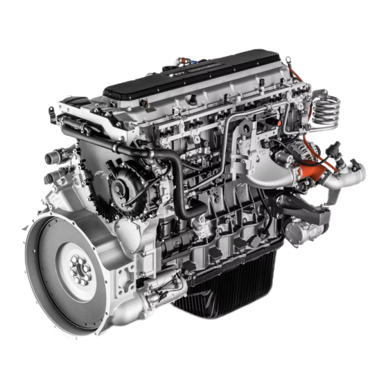
C13ENTZW OVERVIEW

- Heat exchanger lubricant oil
- Oil sump
- Oil sump drain plug
- Lubrication oil filter
- Coupling of engine coolant return fitting -
- Turbocharger
- Turbocharger gas outlet pipe
- Electrically controlled engine brake valve

- Lifting eyelet
- Electronic control unit ECU
- Lubricant oil level dipstick
- Alternator
- Fuel filter
- Electric starter motor
- Engine air inlet pipe
- High and low pressure pump for common rail system
- Engine oil filler cap

- Turbocharger
- Thermostat unit and cylinder head water outlet pipe
- Water pump
- Fan control joint
- Engine flywheel pulley
- Automatic tensioner
- Alternator
- Lubricant oil level dipstick -
- Intake manifold inlet

- Blow-by breather housing
- Engine flywheel
- Oil sump
- Oil sump drain plug
- Lubrication oil filter
- Electrically controlled exhaust brake valve
- Turbocharger
- Lifting eyelet
- Engine oil filler cap
NAMEPLATES
IDENTIFICATION PLATE

- Commercial code
- Engine serial number
TYPE-APPROVAL PLATE

"DELEGATED ASSEMBLY" PLATE
This plate highlights the fact that the engine must be installed with the corresponding ATS system by the bodybuilder. When installation has been completed, it must be removed.

LABELS
Some warning labels (below the description) are affixed to the engine.
NOTE: labels containing an exclamation mark highlight a potential danger.

USE
PRELIMINARY CHECKS
Each time before starting the engine:
- Check and top up the level of the technical fluids, if necessary (fuel, engine oil and coolant).
- Make sure that the air intake filter is not obstructed or clogged.
- Make sure that the batteries are efficient and that the terminals are correctly connected.
ATTENTION!
Make sure that the environment where the engine will operate is free of combustible vapours or gases. Make sure that there is sufficient ventilation and a suitable exhaust gas extraction system for closed environments.
FOR PROPER USE OF THE ENGINE
- Before starting the engine each time, check that the tank contains a sufficient amount of fuel.
- Avoid prolonging the duration of the start control.
- Follow the prescriptions shown on the maintenance plan.
- During use, check periodically that:
- the temperature of the engine coolant does not reach the alarm thresholds;
- the oil pressure remains within normal values.
- The speed and power values must comply with that specified in the technical-commercial documentation.
- Particular attention must be paid to engines that equip the emergency generating units for which frequent efficiency checks are required in order to guarantee their prompt start in all cases when required.

In case of use in extremely dusty environments and according to the final configuration of the generator, soundproofed or without hood, special protections must be provided on the most sensitive components.
SPECIAL WARNINGS
Coolant circuit
When the engine is running, check regularly that the engine coolant temperature does not reach the alarm threshold.
If the detected temperature is too high, disconnect the load and shut down the engine in order to check the cooling circuit conditions.
ATTENTION!
When the engine is hot, pressure builds up in the cooling circuits which may eject hot liquid violently, resulting in a risk of burns. Open the filler cap of the coolant tank only when the engine is cold.
Check the following:
- tension of the auxiliary units transmission belt;
- efficiency of the thermostatic valve;
- conditions of the heat exchanger (clean if necessary).
Lubrication circuit
Regularly check that the oil pressure keeps within normal values. In case the value detected is too low, check the oil level and refill if necessary following the instructions reported in the CONTROLS AND MAINTENANCE section.
If the conditions persist, contact the Service Centre.
Fuel circuit
It is advisable to drain the water from the filters before the relevant warning light comes on.
Do not use the engine if the tank only contains the quantity of fuel kept as reserve; this condition promotes the formation of condensate and the intake of sludge or air, causing the engine to stop.
ATTENTION!
Pay maximum attention when refuelling, making sure that solid or liquid pollutants do not enter the tank; please remember that smoking is prohibited while refuelling.
ATTENTION!
Never loosen the high pressure fuel circuit connectors in any way
Intake and exhaust circuit
Regularly inspect the cleanliness of the air intake inlets and the exhaust ducts. The maintenance intervals indicated in this manual will vary depending on the conditions of use of the engine.
In particularly dusty environments the maintenance frequency must be increased from that shown in section CHECKS AND MAINTENANCE.
ATTENTION!
Visually check that the exhaust circuit is not obstructed or damaged to prevent noxious and harmful fumes inside the ducts.
Electrical system irregularities
Check periodically the cleanliness and efficiency of the batteries, particularly during winter, performing checks and top ups as indicated in the CONTROLS AND MAINTENANCE chapter; close attention must be paid to the caution notices. In the event of battery replacement, observe the characteristics contained in the ENGINE TECHNICAL DATA section.

If the voltmeter indicates a voltage value lower than 22 V, contact a specialised workshop and have the efficiency of the batteries and charging system diagnosed.
ATS system
This system is used to limit the nitrogen oxide (NOx) emissions in the exhaust within the limits required by standards, transforming the nitrogen oxide into inert compounds: free nitrogen (N2) and water vapour (H2O).
Periodically check the system using PT-Box and clean the filters at the intervals indicated in the chapter CHECKS AND MAINTENANCE.
RUN-IN
Thanks to the new engine technology, no running-in is required.
CHECKS AND MAINTENANCE
MAINTENANCE PERSONNEL
The engine check and maintenance operations specified in this chapter require preparation, skill and compliance with safety standards; therefore, they must be carried out by responsible personnel, as indicated below.
- Checks to be made during the period of use: by workshop staff or by the user of the machine, if necessary.
![]()
Periodic maintenance: by qualified personnel equipped with proper work tools and suitable protections.![]()
Unscheduled maintenance: by qualified Service Centre personnel in possession of precise technical information and specific equipment.
The most qualified Service Centres are those included in the FPT Technical Service Network.
ACCIDENT PREVENTION
- Always wear safety footwear, gloves and suits.
- Do not wear loose clothing, rings, bracelets and/or necklaces near the engines or moving parts.
- Wear protective gloves and goggles while:
- filling the batteries with acid solution
- filling up inhibitors or antifreeze
- changing or filling the lubricant oil (hot engine oil can cause burns. It is recommended to perform these operations only when their temperature is lower than 50°C).
- When working in the engine compartment, pay maximum attention to all movements to avoid coming into contact with rotating or hot components.
- Wear goggles when using compressed air (the maximum air pressure used for cleaning is 200 kPa (2 bar, 30 psi, 2 kg/cm2).
- Wear a protective helmet if working in an area with suspended loads or overhead systems.
- Use protective creams for hands.
- Replace wet gloves immediately.
- Always keep the engine clean, removing spots of oil, diesel and coolant.
- Return oily rags to fire-proof containers.
- Do not leave foreign objects on the engine.
- Use suitable, safe containers for used oil.
- At the end of a repair, implement suitable measures to stop air intake by the engine if, after starting, the engine runs at uncontrolled speeds.

Do not perform maintenance in the case of live electrical voltage: check the condition of the equipment's ground connection. During the diagnostics and maintenance operations, make sure your hands and feet are dry and use insulating footboards if possible.
The conditions that cause an emergency generator set to start can occur suddenly. While performing checks and maintenance, comply strictly with the requirements indicated by the Manufacturer of the generator set and by the Fitter of the electric generation system to ensure maximum safety for maintenance personnel
REFUELLING
| Parts to be refilled | C13ENTZW litres (kg) |
| Cooling circuit (1) | 19.5 |
| Lubrication circuit(2) total capacity(3) | 32 (28.8) |
| Periodic replacement: | |
| Sump at minimum level Sump at maximum level | 20 (18) 28 (25) |
| Fuel tank (4) | - |
| Urea tank (5) | 61/75/156 |
(1) The quantities indicated only refer to the engine in its standard configuration. Use a 50% mixture of water and Actifull OT CONCENTRATE (or Actifull OT PREMIX without adding water) even during the summer months. As an alternative to Actifull OT, use another product that complies with FPT norm FPI9.COOL002 and / or ASTM D-6210 standard.
(2) See "Main oil features".
Oil consumption is considered acceptable up to quantities of 0.25% of fuel consumption.
(3) The quantities indicated relate to the first refill only and are relative to the engine, oil sump and filter filling.
(4) Fuel tank not supplied by FPT. Refer to the data of supplier / manufacturer of the generator set.
Use STANDARD fuel which complies with standards ASTM D975 or EN 590.
(5) Only use AdBlue®/DEF in compliance with the specification ISO 22241.
Filling from drums or tanks can cause contamination of the diesel, with the following risk of damaging the injection system; if necessary, perform suitable filtration or sedimentation of the impurities before refuelling.
Diesel oil for low temperatures
Standard EN590 defines the diesel classes, identifying the characteristics of those most suitable for use at low environmental temperatures.
Failure to observe the standards concerning the distribution of fuels suitable for climatic and geographic conditions of the various countries is the exclusive responsibility of the oil companies.
Main oil characteristics
| Oil quality | SAE grade | Base stock | International specifications | Fuel sulphur content |
| Premium | 10W-40 | Semi - Synthetic | API CJ-4 ACEA E6/E9 | < 500 ppm |
| Cold climate | 5W-30 | Synthetic | API CH-4/ CI-4/CJ-4 ACEA E4/E6 | < 500 ppm |
| Not permitted | Single-grade |
Replacement frequency
| Engine/Oil replacement frequency | Premium and cold climate | ||
| CURSOR | 600 h or 12 months |
FREQUENCIES
The frequencies indicated below take into account factors of use of different engine uses; the most suitable duration of the maintenance intervals for the different applications shall be indicated by the maintenance personnel based on the use and operating conditions of the engine.
| Checks to be made during periods of use | Frequency |
| Check the engine lubricant oil level | every start-up |
| Check engine coolant level | every start-up |
| Visual inspection of the engine | hours |
| Verification of the tightening and state of the auxiliary belt | hours |
| Inspection of the exhaust duct/s | Six-months |
| Periodic maintenance | Frequency |
| Draining the water from the fuel pre-filter | hours (1) |
| Change engine lubricant oil | hours (2) (3) |
| Replacing the engine oil filter | hours (2) (3) (4) |
| Fuel pre-filter change | hours (1) (5) |
| Fuel filter replacement | hours (1) (2) (4) |
| Periodic maintenance | Frequency |
| Ancillary belt replacement | hours |
| Check turbocharger connection pipes and wastegate linkage | hours |
| Replacing blow-by filter element | hours (2) |
 Unscheduled maintenance: | Frequency |
| Check tappets clearance and adjust if necessary | hours |
| Change the engine coolant | hours (5) |
1) Maximum period relating to the use of high quality fuel, (specification ASTM D975 or EN 590); which is reduced in the event of fuel contamination and alarm signals caused by filter clogging and/or the presence of water in the pre-filter. The filter clogging signal indicates that the filter must be replaced. If the warning light of water present in the pre-filter does not go off after drainage, then the pre-filter must be replaced.
2) To be performed every year even if the specified interval of operating hours has not been reached.
3) Frequencies are valid for lubricant oils which comply with the international specifications as indicated in the FLUIDS table.
4) Only use filters with the following specifications:
- degree of filtering < 12 μm
- filtering efficiency 99.5% (ß > 200).
5) To be performed every two years even if the specified number of operating hours has not been reached.
The operations described above require the use of specific tools which guarantee safe and effective results. It is recommended that such operations are carried out by qualified personnel of the FPT Technical Service Network.
| Scheduled maintenance of ATS system | Action |
| Tank pre-filter (300 μm or 100 μm (1)) | No maintenance anticipated (clean if necessary) |
| Pre-filter supply module (100 μm or 70 μm (1)) | Clean with water each time the oil is changed (2) |
| AdBlue inlet filter to supply module (100 μm) | No maintenance anticipated (clean if necessary) |
| Filter supply module | Replace every 1200 hours (3) |
| AdBlue return filter from supply module to tank (100 μm) | No maintenance anticipated (clean if necessary) |
| Dosing module filter (36 μm) | Not serviceable |
1) For applications operating in dusty environments.
2) To be performed every year even if the specified interval of operating hours has not been reached.
3) To be performed every two years even if the specified number of operating hours has not been reached.
ATS System filter location

- Dosing valve filter (36 μm)
- Dosing module
- Supply module main-filter
- Supply module backflow-filter (100 μm)
- Supply module pre-filter (100 or 70 μm)
- AdBlue tank
- Tank neck filter (300 or 100 μm)
- Supply module inlet filter (100 μm)
- Supply module
GUIDELINES
- Do not disconnect the battery supply while the engine is running.
- Do not perform arc welding near the engine without first removing its electrical wiring.
- After all maintenance operations that require disconnection of the batteries, make sure the clamps have been securely reconnected on the poles.
- Do not use a battery charger to start the engine.
- Electrically disconnect the battery/ies from the network during charging.
- Do not paint the devices, components and electrical connectors of the engine equipment.
- Electrically disconnect the battery/batteries before performing any electrical work.
- Contact the Manufacturer before installing any electronic equipment.

Do not perform any operation that would change the calibration of the injection pump.
It was adjusted during the engine test phase and based on its destination.
CHECKS TO BE MADE DURING PERIODS OF USE – HOW TO PROCEED
Check the engine lubricant oil level
Only proceed when the engine is not turning and is at low temperature in order not to run the risk of burns; make sure the engine is level or in its normal operating position in order to obtain an accurate oil level reading.
- Use the oil level dipstick (2) to check that the lubricant oil level is between the "Min" and "Max" limits.
- If the level is insufficient, it is necessary to top up with lubricant oil that complies with the international specifications, as indicated in the section FLUIDS: remove the lubricant oil cap (1) and pour engine lubricant oil through the hole.

![]()
Clean the oil cap before performing the operation so as to minimize the risk of contaminating the system. - Use the oil level dipstick (2) to check that the lubricant oil level does not exceed the "Max" limit on the dipstick.

Make sure that the dipstick is fully inserted and that the filler plug is tightened fully in the clockwise direction.
Engine coolant level check (demonstrative)
Proceed only if the engine is not in operation and at low temperature, in order to prevent the risk of burns.
- Remove the pressurization cap from the expansion tank.
- Check that the coolant in the expansion tank is above the minimum level.
- Top up the expansion tank with fluids as required and as indicated in the FLUIDS section.
- Top up the expansion tank until the "MAX" limit is reached; if there is no level indicator on the expansion tank, make sure that the coolant in the expansion tank is a few centimetres below the filling hole in order to allow an increase in the coolant volume following a rise in temperature.
When the engine is hot, pressure builds up in the cooling circuits which may eject hot liquid violently, resulting in a risk of burns.
Open the filler cap of the coolant tank only if necessary and only when the engine is cold.
Clean the pressurization cap of the expansion tank before performing the operation so as to minimize the risk of contaminating the system.
Visual inspection of the engine
Perform a thorough check before start-up in order to obtain maximum engine duration.
Check for any leaks (oil, coolant and fuel), broken or weakened pipes, loose clips and bolts, worn belt, wiring (loose connections, worn or frayed cables) and a build-up of dirt; in the event of any problems, perform the operations necessary to restore the engine.
Any spilt fluid must be removed for all types of leak (coolant, oil or fuel).
If a leak is discovered then find its source and carry out the necessary repair.
A build-up of oil or grease on the engine represents a fire risk.
Verification of the tightening and state of the auxiliary belt
Proceed only if the engine is not in operation and at low temperature, in order to prevent the risk of burns.
- Check that the belt is not worn, soiled with oil or fuel, or showing signs of tears. Otherwise replace the belt if necessary.
- Use a ½ inch square wrench to check the efficiency of the automatic belt tensioner.


When the engine is off, but still hot, the belt may start to move without warning. Wait for the engine temperature to decrease to prevent serious danger of an accident.
Inspection of the exhaust duct/s
Visually check that the exhaust system for exhaust gases is not obstructed, corroded or damaged.
If a fault is found, carry out the necessary procedures to recondition the exhaust duct.
PERIODIC MAINTENANCE - HOW TO PROCEED
Draining the water from the fuel pre-filter
In there is a high risk of refuelling with fuel polluted with foreign bodies and water, the following check should be performed at each refuelling. Proceed when the engine is not running.
- Place a container for collecting liquids under the pre-filter (2).
- Unscrew the valve plug (1) located at the bottom of the filter; in some versions, the plug includes the water in diesel sensor.
- Drain the liquid until only "diesel" is released.

- Fully re-tighten the plug manually. q Dispose of the drained liquids according to the applicable regulations in force.

Clean the cock tap (1) before performing the operation so as to minimize the risk of contaminating the system.
Change engine lubricant oil
Proceed only if the engine is not in operation and at low temperature, in order to prevent the risk of burns.
- Place a suitable container for collecting the spent oil under the oil sump next to the lubricant oil drain plug (3).
- Unscrew the lubricant oil drain plug (3); afterwards extract the oil level dipstick (2) and remove the lubricant oil cap (1) to assist the flow of the engine lubricant oil.
- Wait until the oil sump has completely emptied, then re-tighten the lubricant oil drain plug (3) to the torque indicated in the table
- Proceed with the refilling operation through the hole (1) situated on the tappet cover, using lubricant oil that complies with the international standards as indicated in the FLUIDS section.
- Use the oil level dipstick (2) to check that the lubricant oil level does not exceed the "Max" limit.
- Retighten the lubricant oil cap (1).
- The oil filter has to be replaced when the engine lubricant oil is changed (see the paragraph entitled OIL FILTER REPLACEMENT).
| Ref. | No. | Description | Torque |
| 3 | 1 | Oil drain plug | 95 ± 10 Nm |
Clean the plugs before performing the operations so as to minimize the risk of contaminating the system.
After changing the engine lubricant oil, make sure that the level does not exceed the "Max" limit on the oil level dipstick.
Make sure that the dipstick is fully inserted and that the filler plug is tightened fully in the clockwise direction.

Dispose of consumable materials and parts in contact with them (e.g. filters) in accordance with the law.
Replacing the engine oil filter
Only use filters with the following specifications:
- degree of filtering < 12 μm
- filtering efficiency ß > 200 (99.5%)
Proceed only if the engine is not in operation and at low temperature, in order to prevent the risk of burns.
- Proceed with draining the spent lubricant oil (see paragraph ENGINE LUBRICANT OIL REPLACEMENT).
- Place a suitable container for collecting the spent oil under the oilfilter next to the drain plug (3).
- Remove the filter (4) by unscrewing it.
- Replace the filter element (2) and the O-ring seal (1) contained inside the filter body (4).
- Carefully clean the surfaces
- Moisten the O-ring seal (1) of the new filter with oil.
- Tighten the drain plug (3) and the filter body (4) to the torque indicated in the table.

- Proceed with the refilling operation of the lubricant oil (see the paragraph entitled ENGINE LUBRICANT OIL REPLACEMENT).

Operate the engine for a few minutes and then check the level using the dipstick.
If necessary, top up to compensate for the quantity of oil used to refill the filtering cartridge.
| Ref. | No. | Description | Torque |
| 1 | 1 | Engine oil filters | 60 ± 5 Nm |
| 3 | 1 | Drain plug on engine oil filter | 6.5 ± 1.5 Nm |

After changing the engine lubricant oil, make sure that the level does not exceed the "Max" limit on the oil level dipstick.
sure that the dipstick is fully inserted and that the filler plug is tightened fully in the clockwise direction.
Replacement of fuel pre-filter (demonstrative)

Dispose of consumable materials and parts in contact with them (e.g. filters) in accordance with the law.
Proceed only if the engine is not in operation and at low temperature, in order to prevent the risk of burns.
- Close the tank cock.
- Place a suitable container for collecting the fuel under the fuel prefilter next to the bleeder plug or, if present, the water presence sensor (2)
- Remove the filter cartridge (1)
- Moisten the O-ring seal (3) of the new filter with oil.
- Screw the cartridge by hand until it comes into contact with the support and then tighten it to the torque indicated in the table.
- Reconnect the lower electric connection of the water presence sensor, if present.
 - Step 1")
 - Step 1")
| Ref. | No. | Description | Torque |
| 1 | 1 | Fuel pre-filter cartridge | 19.5 ±1 Nm |
Do not fill the new pre-filter until it has been positioned on the support: this prevents allowing impurities to enter and damage the circuit and injection system.
Dispose of consumable materials and parts in contact with them (e.g. filters) in accordance with the law.
- Loosen the following bleeder connections and connect them with appropriate pipes to allow any residue to drain into suitable containers so as to prevent soiling:
- Screw (1) located on the pre-filter support.
- Bleeder connection (3) situated on the filter support.
- Actuate the pump (2) located on the fuel pre-filter (responsibility of the manufacturer of the vehicle/outfitting) until the fuel comes out of the bleed screw (1) with no sign of any air bubbles; upon completion of the operation tighten the screw.
- Continue to operate the pump until fuel flows out without air from the bleeder connection (3) situated on the fuel filter; upon completion of the operation tighten the screw.
![]()
Take utmost care to prevent any fuel from soiling the control belt
 - Step 2")
- Tighten the bleeder screws to the prescribed torque.
 - Step 2")
| Ref. | No. | Description | Torque |
| 1 | 1 | Pre-filter bleeder screw | 18 ±2 Nm |
| 3 | 1 | Bleeder connection | 18 ±2 Nm |
- Start the engine and allow it to idle for a few minutes to expel any residual air from the circuit.
For the engine to function correctly the fuel circuit must be free from air.
Fuel filter replacement
Proceed only if the engine is not in operation and at low temperature, in order to prevent the risk of burns.
- Close the tank cock.
- Place a suitable container for collecting the fuel under the fuel filter next to the drain plug (4).
- Open the drain plug (4) and the bleeder connection (5) and drain any residual fuel.

- Remove the filter element (2) by unscrewing the relative bell-shaped support (3).
- Replace the filter element (2) and the O-ring seal (1) contained inside the bell-shaped support (3).
- Moisten the O-ring seal (1) of the filter with oil.
- Insert the filter element (2) and tighten the relative bell-shaped support (3) to the torque indicated in the table.
- Tighten the drain plug (4) to the torque indicated in the table.


Do not fill the new filter until it has been positioned on the support: this prevents allowing impurities to enter and damage the circuit and injection system.
| Ref. | No. | Description | Torque |
| 3 | 1 | Fuel filter | 32.5 ±2.5 Nm |
| 4 | 1 | Threaded plug | 1.5 ±0.5 Nm |
| 5 | 1 | Bleeder connection | 18 ±2 Nm |
- Loosen the following bleeder connections and connect them with appropriate pipes to allow any residue to drain into suitable containers so as to prevent soiling:
- Screw (1) situated on the pre-filter support.
- Bleeder connection (3) situated on the filter support.
- Actuate the pump (2) located on the fuel pre-filter (responsibility of the manufacturer of the vehicle/outfitting) until the fuel comes out of the bleed screw (1) with no sign of any air bubbles; upon completion of the operation tighten the screw.
- Continue to operate the pump until fuel flows out without air from the bleeder connection (3) situated on the fuel filter; upon completion of the operation tighten the screw.

![]()
Take utmost care to prevent any fuel from soiling the control belt - Tighten the bleeder screws to the prescribed torque.

| Ref. | No. | Description | Torque |
| 1 | 1 | Pre-filter bleeder screw | 18 ±2 Nm |
| 3 | 1 | Bleeder connection | 18 ±2 Nm |
- Start the engine and allow it to idle for a few minutes to expel any residual air from the circuit.
For the engine to function correctly the fuel circuit must be free from air.
Dispose of consumable materials and parts in contact with them (e.g. filters) in accordance with the law.
Change the ancillary belt
Proceed only if the engine is not in operation and at low temperature, in order to prevent the risk of burns.
- Using a 1/2 inch square wrench, operate on the belt tensioner (1) and pull off the crankshaft / electromagnetic coupling / water pump / alternator (A) pulley drive belt.

- Replace the worn belt with a new one and fit it on the pulleys and guide rollers.
- Using the aforesaid tools, operate on the automatic belt tensioner in order to force fit the new belts in their operating position.

Replace the belt if there are any signs of abrasion, cracks or tears, oil or fuel stains
When the engine is off, but still hot, the belt may start to move without warning. Wait for the engine temperature to decrease to prevent serious danger of an accident.
Check turbocharger connection pipes and wastegate linkage
- Only proceed when the engine is not turning and is at low temperature so as not to run the risk of burns.
Turbocharger lubricant pipe tightness check
- Check the tightening torque of the connections (1,2) and perform a visual inspection to check for any oil leaks.
- In the event of an oil leak replace the gaskets (3,4) of the connectors (1,2).


The exhaust pipes must not have sharp bends and angles of less than 30°
The flange replacement gaskets and fixtures must be fitted without sealant: this may contaminate the oil.
Turbocharger gasket seal check
- Check that there are no deposits of soot between the intake manifold and the turbocharger. Replace the gasket if required.
- Check the turbocharger gasket for any signs of breaks or distortions and replace it, if necessary.


Turbocharger blade check
- Check for the presence of cracks on the turbocharger.
- Check that there are no bent or damaged blades in the compressor impeller.
Wastegate linkage check
- Check that the wastegate control linkage is fully tightened, lubricated and not deformed.
Replacing blow-by filter element
- Unscrew the screws (3) and remove the cover (4)
- Unscrew the screws (2) and remove the blow-by filter element (1)
![]()
Carefully clean the filter seat and the cover. - Position the new blow-by filter element (1) in its seat.
- Apply some Loctite 243 on the screws (3) and tighten them to the torque indicated in the table.
- Position the cover (4) and tighten the screws (3) to the torque indicated in the table.


| Ref. | No. | Description | Torque |
| 2 | 4 | Fastening screws for blow-by filter element Pre-tightening Tightenin | 5 Nm 15 Nm |
| 3 | 6 | Fastening screws for blow-by cover | 7 ± 1 Nm |
Dispose of consumable materials and parts in contact with them (e.g. filters) in accordance with the law.
UNSCHEDULED MAINTENANCE - HOW TO PROCEED
Check tappets clearance and adjust if necessary
Adjustment of the play between the rocker arms and the intake and exhaust valve control rods must be performed with great care. Bring the cylinder whose clearance needs to be adjusted to the combustion stage; the valves of this cylinder will be closed while those of the symmetrical cylinder are balanced. The symmetrical cylinders are 1-6, 4-3 and 2-5.
Using a box-end wrench loosen the nut (1) securing the adjustment screw.
Insert the feeler gauge blade (3) corresponding to the operating clearance.
a suitable wrench, tighten or loosen the rocker arm adjustment screw (2).
Check that the feeler gauge blade (3) can slide freely.
Lock the nut (1) keeping the adjustment screw so it does not move.

The values to be checked are detailed below:
Intake valve: 0.40 ± 0.05 mm
Exhaust valve: 0.60 ± 0.05 mm
The operations described above require the use of specific tools which guarantee safe and effective results.
It is recommended that such operations are carried out by qualified personnel of the FPT Technical Service Network.
Changing the engine coolant (by way of example)
- Only proceed when the engine is not turning and is at low temperature so as not to run the risk of burns.
- Place a container for collecting coolant under the heat exchanger (radiator).
- Remove the pressurization cap from the expansion tank.
- Loosen the fastening elements and remove the coupling sleeves connecting the engine cooling circuit to the heat exchanger.
- Drain the coolant from the heat exchanger (radiator) and wait until it is completely empty.
- Once emptied, restore the integrity of the cooling circuit, by ensuring the perfect seal of the sleeves.
- Fill the engine and the heat exchanger until the cooling circuit is filled completely, as indicated in the FLUIDS section. Do not fill the expansion tank to the brim.
- With the coolant filler plug open, start the engine and let it idle for approx. one minute. This helps to completely bleed the air contained in the cooling circuit.
- Stop the engine and then top up with coolant if necessary.
- When the engine is cold, make sure that the coolant in the expansion tank is a few centimetres below the filling hole.
- If there is an external level indicator on the heat exchangers, proceed with the top-up making sure that the coolant does not completely fill the exchanger. This is to allow an increase in the coolant volume following a rise in temperature.
Failure to observe the procedure does not guarantee the presence of the correct amount of coolant in the engine.
When the engine is hot, pressure builds up in the cooling circuits which may eject hot liquid violently, resulting in a risk of burns. Open the filler cap of the coolant tank only if necessary and only when the engine is cold.
ENGINE HANDLING
The engine must only be removed and installed by Service Centre personnel.
To lift only the engine use the eyelets specified in this manual in the ENGINE TECHNICAL DATA section and marked on the engine with specific plates.
It must be hoisted using a rocker arm that keeps the wire cables that support the engine parallel, using all the provided eyelets at the same time; it is not permitted to use just one eyelet.
The capacity and dimensions of the engine hoisting system must be suitable for the engine weight and dimensions; make sure there is no interference between the hoisting system and the engine components. Do not hoist the engine before removing the transmission components coupled to it.
DISPOSAL OF WASTE
The engine consists of parts and elements that can cause ecological damage if disposed of in the environment.
The materials listed below must be delivered to authorised collection Centres; The laws in force in the different countries foresee severe penalties for violators:
- Starter batteries.
- Spent lubricant oils.
- Water and antifreeze mixtures.
- Filters.
- Auxiliary cleaning material (e.g. rags soaked in or moistened with fuel).
SCHEDULED MAINTENANCE FOR THE ATS SYSTEM - HOW TO PROCEED
Change Supply Module main-filter
To prevent damage to the pump and dosing module, the supply module contains a filter which removes any impurities from the AdBlue.
Please refer to the following procedure for replacement of the filter.

- Coolant connector
- AdBlue inlet from tank
- AdBlue back-flow to tank
- AdBlue outlet to Dosing Module
- Pressure sensor
- Supply Module main-filter
- Membrane pump
- 4/2 Way valve.
Filter disassembly
- Unscrew and remove the filter cover (1).
- Remove the equalizing element (2).


During installation of the supply module on the vehicle, take into account the minimum aperture for filter replacement.
The minimum value is approx. 155 mm.
- Insert the appropriate tool (1) in the correct direction in the filter, based on the colour of the filter supplied.
- Insert the appropriate tool (1) until a click is felt which indicates the complete engagement of the filter (2).
- Remove the filter (2).


Filter assembly
- Carefully clean with water the contact surface (1).
- Moisten the gasket (3) and fit the new filter (2).

- Assembly a new equalizing element (2).
- Carefully clean the filter cover (1).
- Tighten the filter cover (1) to a torque of 20 ± 5 Nm.


Check that the filter cover and the contact surface of the supply module are not cracked or damaged.
If necessary, replace any damaged components.
LONG PERIOD OF ENGINE INACTIVITY
PREPARING THE ENGINE FOR A LONG PERIOD OF INACTIVITY
In the case of a planned period of inactivity that lasts longer than two months, to prevent the interior parts of the engine and some components of the injection system from oxidising, prepare the engine as follows:
- Drain the lubricant oil from the sump after heating the engine.
- Introduce protective oil (in compliance with standard MIL-L-2160Btype 2 / ISO 3498/6743-4 HM) into the engine until it reaches the "minimum" level shown on the dipstick. Start the engine and run it for approx. 5 minutes.
- Drain the fuel from the injection circuit, from the filter and from the injection pump channels.
- Connect the fuel circuit to a tank containing CFB protective liquid(ISO 4113) and introduce the liquid by pressurising the circuit and driving the engine for approx. 2 minutes, after excluding the operation of the injection system. This operation can be completed by directly polarising terminal 50 of the electric starter motor with a positive voltage equivalent to the rated voltage of the system, using a conductor provided for that purpose.
- Nebulize approx. 130 g of the protective oil (10 g per litre of displacement) in the intake manifold while the engine is turning over as described in the previous paragraph.
- Close all of the engine's intake, discharge, ventilation and bleeding holes with plugs or seal them with adhesive tape.
- Drain the residual 30/M protective oil from the sump, which can be reused for another 2 preparations.
- Place warning notices of ENGINE WITHOUT OIL on the engine and dashboard.
- Drain the coolant, if it hasn't needed to be mixed with anti-freeze and corrosion inhibitors, indicating marks that the operation has been completed.
In the case of prolonged inactivity, repeat these operations every 6 months, according to the following procedure:
- drain the 30/M protective oil from the sump;
- repeat the operations from point 2 to point 7.
If you intend to protect the external parts of the engine, spray all uncoated metal parts such as the flywheel, pulleys, and other, with protective fluid (Anticorit), avoiding belts, connector cables, and electric equipment.
Protect the connectors and electrical connections using VCI spray.
Wrap the engine in a VCI bag with hygroscopic salt filled bags.
ENGINE START-UP AFTER A LONG PERIOD OF INACTIVITY
- Drain the residual protective oil from the sump.
- Add the type and quantity of lubricant oil to the engine as specified in the REFUELLING table.
- Drain the protective fluid CFB from the fuel circuit bringing to a close the operations as indicated in point 3 of the PREPARATION OF THE ENGINE FOR A LONG PERIOD OF INACTIVITY.
- Remove the plugs and/or seals from the engine's intake, discharge, ventilation and bleeder holes, restoring normal conditions of use. Connect the turbocharger intake inlet to the air filter.
- Join the fuel circuits to the machine's tank bringing to a close the operations as indicated in point 4 of the PREPARATION OF THE ENGINE FOR A LONG PERIOD OF INACTIVITY. During the filling operations, connect the tank fuel return pipe to a collection container to prevent the residual CFB protective liquid from flowing into the car's tank.
- Check and fill the engine with coolant as required, degassing if necessary.
- Start the engine and let it idle until completely stabilized.
- Check that the indications on the dashboard instruments are plausible and that there are no alarm warning signals.
- Stop the engine.
- Remove the warning notices of ENGINE WITHOUT OIL from the engine and dashboard.
ENGINE FAULTS
The Electronic Unit that manages and controls all engine operations is able to detect the occurrence of faults and adopt strategies to proceed in a safe manner.
The event, signalled by the switching on of the EDC Fault indicator on the dashboard involves the programmed limitation of power within the thresholds determined based on the severity of the situation. In the case of temporary faults, the performance will be reduced until the engine stops.
BEHAVIOURS IN CASE OF EMERGENCY
The user of the vehicle, which has been constructed according to safety regulations, is able to operate safely by following the indications provided in this manual and assisted by the indications provided on the engine labels.
If incorrect behaviours cause accidents, request the immediate assistance of specialised first aid personnel.
In the case of an emergency and while waiting for rescue personnel, the following instructions are provided.
Engine faults
If proceeding with the engine in a faulty state, pay maximum attention to the maneuvers and check that any people on-board are secured to secure grips.
Fire
Put out the fire using the designated devices and according to the methods indicated by the competent authorities (fire suppression equipment for some cars and vehicles has been made mandatory by current safety regulations).
Burns
- Put out the flames on the clothing of the burn victim by means of:
- flooding with water;
- use of powder extinguishers, without directing the jet towards the face;
- covers or rolling the victim on the ground.
- Do not remove the shreds of clothing that adhere to the skin;
- If the burns are caused by liquids, quickly but carefully remove the clothing saturated with the hot liquid;
- Cover the burn with an anti-burn pack or with a sterile bandage.
Carbon monoxide (CO) poisoning
The carbon monoxide contained in the engine's exhaust gas is dangerous both because it causes poisoning as well as because it forms an explosive mixture with the air.
In closed areas, carbon monoxide is very dangerous because it can reach a critical concentration in a short period of time. If aiding a poison victim in a closed room:
- Immediately ventilate the room to reduce the concentration of gas.
- When accessing the room, the rescuer must hold his/her breath, not light flames, turn on lights or activate electric bells or telephones in order to prevent explosions.
- Bring the poison victim to safety in a ventilated room or in the open air, placing the victim on his/her side if unconscious.
Electrocution
The engine's 24 V electrical system does not involve electrocution risks. However, if there is a short circuit caused, for example, by a metal tool, there may be risks of burning due to the overheating of the object as a result of the conduction of electric current. In that case:
- Remove the object that caused the short circuit by using means that provide sufficient thermal insulation.
- If present, use the main switch to cut off the power supply.
Injuries and fractures
The seriousness of the cases and the specific nature of the interventions means that medical professionals must intervene.
- If the victim is bleeding, compress the injury externally until the rescuers arrive.
- If there is a possibility of fractures, do not move the affected part and transfer the injured person very carefully and only if absolutely necessary.
Corrosion
Skin corrosion is caused by contact with substances with a high degree of acidity or basicity.
For personnel performing maintenance on electrical devices, this is typically caused by acid escaping from the batteries; in this circumstance proceed as follows:
- Remove any clothing saturated with the caustic substance.
- Wash thoroughly with running water, without spraying uninvolved parts.
If battery acid, lubricant oil or diesel has entered the eyes: wash the affected eye with water for at least 20 minutes, keeping the eyelids open so the water flows onto the eyeball (facilitate washing of the eye by moving it in all directions).
RECOMMENDED OPERATING TEMPERATURE RANGE
The viscosity index to be used depends on the ambient temperature, as shown in the figure below:

A: Engine oil sump heater or cooling block recommended in this range
Note: Cold start capabilities are strongly correlated with the quality of the diesel.
Documents / ResourcesDownload manual
Here you can download full pdf version of manual, it may contain additional safety instructions, warranty information, FCC rules, etc.
Advertisement


Need help?
Do you have a question about the CURSOR Series and is the answer not in the manual?
Questions and answers