Table of Contents
Advertisement
Advertisement
Table of Contents

Related Manuals for FPT NF67TE8W.S550


Summary of Contents for FPT NF67TE8W.S550
- Page 1 USE AND MAINTENANCE USO E MANUTENZIONE UTILISATION ET ENTRETIEN BETRIEB UND WARTUNG USO Y MANTENIMIENTO SERIES POWER GENERATION ENGINES Publication edited by: FPT Industrial S.p.A Via Puglia 15, 10156 Torino, Italia www.fptindustrial.com Print L31900356 - 05/17...
- Page 2 NEF SERIES INTRODUCTION We would like to thank you for buying an FPT product, and compliment you on your choice of engine. Before you carry out any operation involving the engine or its fittings, please read the contents of this manual carefully; compliance with the instructions provided in the manual is the best way to guarantee NF67TE8W.S550...
-
Page 3: Table Of Contents
TABLE OF CONTENTS Page GENERAL INFORMATION ..... 3 Guarantee ..........3 Spare parts . -
Page 4: General Information
The use of non-original spare parts will not only invalidate the temperature components and to circuits containing pressurised guarantee, but will mean that FPT will not be considered liable in any fluids; its electrical equipment houses electrical currents and voltage. -
Page 5: Safety Warning Symbols
SAFETY WARNING SYMBOLS You will find these symbols on the following pages; follow the instructions to which they refer, for your own safety and that of your engine. Risk of injury: failure to comply with these instructions General risk: combines the risks of both the signs can result in the risk of serious injury. -
Page 6: Engine Technical Data
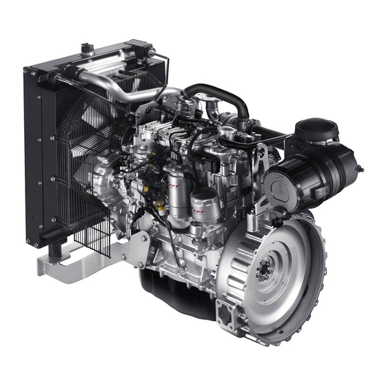
Electric starter motor is located on different parts of the engine, according to the model: - Maximum output power 4 kW flywheel casing, tappet cover, other. Alternator Code NF67TE8W.S550 - Output 70 A Engine family Performance (*) F4HFA615A*D001 Cycle Diesel 4-stroke... - Page 7 17_053_N 17_054_N NF67TE8W.S550 NF67TE8W.S550 1. Turbocharger - 2. Air filter - 3. Blow-by filter - 4. Fuel high-pressure 1. Turbocharger - 2. Tappet cover - 3. Lifting eyelet - 4. Fan - pump - 5. Fuel filter - 6. Oil sump - 7. Pre-fuel filter - 8. Engine Control 5.
- Page 8 17_055_N 17_056_N NF67TE8W.S550 NF67TE8W.S550 1. Air filter - 2. Lifting eyelet - 3. Engine cable - 4. Fan control pulley - 1. Air filter - 2. Air outlet pipe - 3. Turbocharger lubricant oil return 5. Prefuel filter - 6. Fuel filter - 7. Crankshaft pulley with damper - 8. Oil pipe - 4.
-
Page 9: Signs
SIGNS Certain warning signs are affixed to the engine by the Manufacturer, and their meanings are indicated below. N.B. The signs with an exclamation mark on them underline a potential danger. Lifting point (engine only). Danger of burning: Expulsion of hot water under pressure. Fuel Cap Danger of burning: (on the fuel tank, if there is one). -
Page 10: Use
USE Note: the required procedures for filter cleaning are specified in the CHECKS AND MAINTENANCE section. PRELIMINARY CHECKS Before starting the engine every time: CAUTION! Check the level of technical fluids (fuel, engine oil and coolant), and Make sure that no fuel vapours or gasses are present top-up if necessary. -
Page 11: Interconnection Electrical Unit
INTERCONNECTION ELECTRICAL UNIT In order to allow the unit's correct electrical functioning, an interconnection unit has been fitted to the engine. The engine electronic control system and the power unit system depend from the aforesaid interconnection unit. Some indications relating to its components and functions controlled by programming commutators are reported here following. 1 2 3 4 5 6 7 8 1 2 3 4 5 6 7 8 9 10... - Page 12 Relay JP1(Engine speed selection) +JX (Connector: Engine speed selection) ATS intelligent sensor After run B 1500 rpm. (50 Hz) Starter SCR heating Fuel filter heating 1800 rpm. (60 Hz) Pre-fuel filter heating Starter control CN1 Diagnose IDLE Engine speed and accessory functions control Programming of the functions here following is possible commuting the position of the JP switches.
- Page 13 JP3: Cold start heater relay JP5: It CAN line Connected Connected Not connected (default) Not connected (default) JP4: Cold start lamp Connected Not connected (default)
-
Page 14: Special Warnings
SPECIAL WARNINGS Fuel circuit Avoid using the engine with small reserve of fuel in the fuel tank. Thus Coolant circuit the vapour condensation is encouraged and makes the engine more likely to inhale dirt or air, resulting in engine stoppage. When the engine is running, regularly check that the engine coolant temperature does not reach the alarm threshold. -
Page 15: Run-In
RUN-IN Thanks to modern engine design technology, no particular run-in CAUTION! procedure is required. Visually check that the exhaust circuit is not obstructed However, for the first 50 hours, it is not recommended to operate the or damaged to prevent the formation of noxious and engine at high power for long periods. -
Page 16: Checks And Maintenance
Do not leave external objects on the engine. The most qualified Assistance Centres are those which make up the FPT Technical Assistance Network. Use suitable, safe containers for used oil. Once the repair activities are completed, take the necessary steps... -
Page 17: Refilling
(3) The quantities indicated refer to the first filling only and are relative to the engine, oil sump and filter refilling. REFILLING (4) Fuel tank not supplied by FPT.Consult supplier / generator set manufacturers data. Parts to be supplied NF67TE8W.S550 Only use fuels which comply with ASTM D975 or EN 590 international standards. - Page 18 Main oil features Oil Quality SAE grade Base Stock International Spec. Fuel Sulphur Content API CJ-4 Premium 10W-40 Semi Synthetic < 500 ppm ACEA E6/E9 API CH-4/ Cold Climate 5W-30 Synthetic CI-4/CJ-4 < 500 ppm ACEA E4/E6 15W-40 Mineral Semi API CI-4 / Standard 10W-30...
- Page 19 Coolant refilling Refuelling For the initial engine start-up and in the cases in which the refilling of Use only diesel oil in accordance with ASTM D975 or EN 590 the cooling circuit is required with a considerable quantity of coolant, standard normally commercially available.
-
Page 20: Maintenance Schedule
MAINTENANCE SCHEDULE Periodic maintenance Frequency The maintenance intervals indicated below take into account the typical working factors for various types of engine use; the most Hours Temporal suitable interval for maintenance operations for the various Water drainage from the fuel pre-filter* 1 week applications will be indicated by the maintenance staff, according to the way and working conditions in which the engine is used. -
Page 21: Requirements
The extraordinary maintenance operations described hereunder fall within the exclusive competence of manufacturer’s personnel or specialised personnel having proper working tools and adequate protection devices. The procedure and modality for carrying out these operations are illustrated in the FPT Technical and Repair Manual. -
Page 22: Checks (In Period Of Use)
CHECKS (IN PERIOD OF USE) Engine lubricant oil level check The check must be executed when the engine is disconnected and possibly cool. Only proceed with the engine stopped and at low temperature, in order to avoid the risk of burning. ... - Page 23 Engine coolant level check Engine visual inspection Only proceed with the engine stopped and at low temperature, in It is a good habit to execute, before engine start, a series of simple order to avoid the risk of burning. checks that might represent a valid warranty to avoid inconveniences, even serious, during engine running.
- Page 24 Air filter and housing cleanness check Only proceed when the engine is not running. Remove the cover (4) of the air filter after having undone the two quick release clips (3). Remove the filter element (5); make sure that dust does not enter the sleeve during this operation.
- Page 25 Tension and condition check of auxiliary member’s belt Only proceed when the engine is not running and is at low temperature so as not to run the risk of burns. Check that the belt (2) is not worn, soiled with oil or fuel, or showing signs of tears.
- Page 26 Electrolyte level in batteries check Place the batteries on a level surface, then proceed as follows. ATTENTION! Visually check that the fluid level is between the “Min” and “Max” The batteries contain sulphuric acid which is highly limits; in the absence of references, check that the fluid covers the caustic and corrosive;...
-
Page 27: Periodic Maintenance - How To Proceed
Exhaust duct(s) condition check PERIODIC MAINTENANCE - HOW TO PROCEED Visually check that the exhaust gas system is not blocked, corroded or damaged. Water drainage from the fuel pre-filter In the event of any problems, perform the operations necessary to restore the exhaust duct. - Page 28 Condensed water drainage from fuel tank Proceed to the drainage / water extraction, condensation and impurities from the fuel tank following the instructions in the manual provided by the manufacturer of the generator. Proceed as required by structure or location of the tank: engines that operate in harsh environments and conditions and / or which are supplied by drums or canisters, require more care when cleaning the tank.
- Page 29 Heat exchanger (radiator) cleaning Turbocharger visual inspection Check that the air intake surfaces of the radiators are free of impurities Only proceed when the engine is not running. Visually check that the (dust, mud, straw etc.). turbine and compressor impellers and the relative inlet and outlet Clean them if necessary using compressed air or steam.
- Page 30 Manually tighten the new filter (3) on the support (1) until it comes with current regulations. into contact with the gasket (2). Additionally tighten it using a The FPT Technical Service Network workshops are specific tool to a torque of 20 ± 2 Nm. equipped for this purpose.
- Page 31 Eliminate the consumables and any materials in contact with them (for example, filters) in accordance with current regulations. The FPT Technical Service Network workshops are equipped for this purpose. Fuel pre-filter replacement Only proceed with the engine stopped.
- Page 32 Fuel filter replacement Loosen the bleeder screw (1) on the pre-filter support and keep pressing the hand pump (2) until the supply circuit is full. Ensure Only proceed with the engine stopped and at low temperature, in that any fuel coming out is not dispersed into the environment. order to avoid the risk of burning.
- Page 33 Eliminate the consumables and any materials in contact with them (for example, filters) in accordance with current regulations. The FPT Technical Service Network workshops are equipped for this purpose. CAUTION! Ensure that any fuel coming out of the vent plug or drain screw does not dirty the auxiliary members' drive belt and is not dispersed into the environment.
- Page 34 Blow-by filter replacement Air filter replacement The blow-by filter has been developed and equipped for the Refer to the Air filter and housing cleanness check procedure. collection, filtering and condensation of the lubricating oil vapours. Only proceed with the engine stopped and at low temperature, in Auxiliary members' belt replacement order to avoid the risk of burning.
-
Page 35: Extraordinary Maintenance - How To Proceed
EXTRAORDINARY MAINTENANCE - HOW TO PROCEED Adjustment of valve/rocker arm clearance The adjustment of the clearance between the rocker arms and the intake and exhaust valve control rods must be strictly carried out using an Allen wrench (1), box-end wrench (3) and a feeler gauge (2). For details refer to the Technical Repair Manual. - Page 36 Engine coolant replacement Only proceed when the engine is not running, and is at low temperature, to avoid the risk of burns. Place a container for collecting coolant under the heat exchanger (radiator). Remove the pressurization cap (2) from the expansion tank. ...
-
Page 37: Moving The Engine
MOVING THE ENGINE DISPOSAL OF WASTE The operations necessary to disconnect and subsequently reconnect The engine is made up of parts and elements that, if discarded, may cause damage to the environment. the engine must only be carried out by technicians from Authorised The materials listed below must be handed over to specialised Service Centres. -
Page 38: Long Periods Of Inactivity
LONG PERIODS OF INACTIVITY 7. Drain the residual protective oil from the sump. This oil can be used again for a further 2 preparation operations. PREPARING THE ENGINE FOR A LONG 8. Fit signs reading "ENGINE WITHOUT OIL" to the engine and to the on-board control panel. -
Page 39: Restarting The Engine After A Long Period Of Inactivity
RESTARTING THE ENGINE AFTER A LONG PERIOD OF INACTIVITY 1. Drain the residual protective oil from the sump. 2. Fill the engine, as prescribed, with lubricant of the type and amount indicated in the REFILLING table. 3. Drain the CFB protective fluid from the fuel circuit, carrying out this operation as indicated under point 3 of PREPARING THE ENGINE FOR A LONG PERIOD OF INACTIVITY. -
Page 40: Engine Malfunctions
ENGINE MALFUNCTIONS The electronic unit overseeing management and control of all operation of the engine is capable of recognising any malfunctions that may occur, and of adopting strategies that will allow in order to proceed in full safety. The event, signalled by light-up of the EDC MALFUNCTION indicator on the on-board control panels, results in programmed limitation of power within certain thresholds, set according to the severity of the case. -
Page 41: Behaviour In Emergency
BEHAVIOUR IN EMERGENCY Carbon monoxide intoxication (CO) Carbon monoxide from the engine exhaust is without smell, and is The user of a generator set that has been constructed according to dangerous both because it causes intoxication, and because when safety regulations, when following the instructions provided in this combined with air it forms an explosive mixture. - Page 42 Electrocution Caustic burns The engine 24 V electrical system does not involve the risk of Caustic skin burns are caused by contact with extremely acid or electrocution, however, in the event of a short-circuit caused, for alkaline substances. example, by a metal tool, there is a risk of burning due to overheating For electric maintenance technicians these are typically caused by acid of the object through which the electrical current flows.
Need help?
Do you have a question about the NF67TE8W.S550 and is the answer not in the manual?
Questions and answers