
Subscribe to Our Youtube Channel
Related Manuals for FPT N45 AM1S


Summary of Contents for FPT N45 AM1S
- Page 1 USE AND MAINTENANCE USO E MANUTENZIONE UTILISATION ET ENTRETIEN BETRIEB UND WARTUNG USO Y MANTENIMIENTO SERIES G-DRIVE ENGINES Publication edited by Marketing - Adv. & Promotion Print L31900080 - 03/10...
- Page 2 N SERIES INTRODUCTION We would like to thank you for buying an FPT product, and compliment you on your choice of engine. N45 AM1S Before you carry out any operation involving the engine or its fittings, N45 SM1A/SM1X/SM2A/SM2X please read the contents of this manual carefully; compliance with the...
-
Page 3: Table Of Contents
Safety ..........3 Engine technical data N45 AM1S ......4 Engine technical data N45 SM1A/SM1X/SM2A/SM2X N45 TM1A/TM2A . -
Page 4: General Information
The use of non-original spare parts will not only invalidate the fluids; its electrical equipment houses electrical currents and guarantee, but will mean that FPT will not be considered liable in any voltage. way during the whole working life of the engine. -
Page 5: Engine Technical Data N45 Am1S
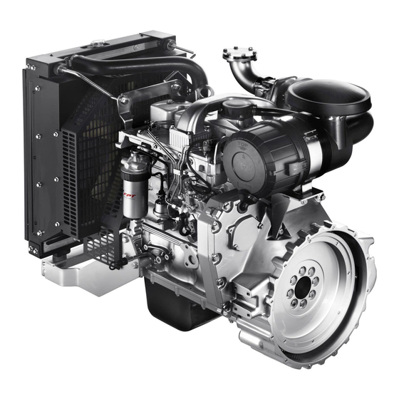
Any alteration of the above mentioned characteristics is strictly Number and arrangement prohibited, penalty invalidation of the guarantee and absence of all 4, in line of cylinders liability on the part of FPT . Bore x stroke 104 x 132 mm Total displacement 4,500 cm... - Page 6 07_001_N 07_002_N N45 AM1S N45 AM1S 1. Lifting U-bolt - 2. Exhaust manifold - 3. Oil vapour bleeder - 1. Heat exchanger - 2. Coolant filler cap - 3. Oil filler cap - 4. Engine air inlet manifold - 5. Injection pump - 6. Air filter - 7. Fuel outlet 4.
-
Page 7: Engine Technical Data N45 Sm1A/Sm1X/Sm2A/Sm2X
~450 kg Any alteration of the above mentioned characteristics is strictly Dry weight ~500 kg prohibited, penalty invalidation of the guarantee and absence of all liability on the part of FPT . 1) Excluding versions SM Electrical system 12 V Accumulator/s... - Page 8 05_611_N 05_612_N N45 SM1A/SM1X/SM2A/SM2X - N45 SM1A/SM1X/SM2A/SM2X - N45 TM1A/TM2A N45 TM1A/TM2A 1. Exhaust manifold - 2. Turbocharger air intake - 3. Turbocharging air 1. Heat exchanger/s - 2. Coolant filler cap - 3. Oil filler cap - 4. Engine outlet - 4.
-
Page 9: Engine Technical Data N67 Tm2A/Tm3A/Tm1X
Any alteration of the above mentioned characteristics is strictly Injection type Direct with rotating pump prohibited, penalty invalidation of the guarantee and absence of all Engine direction of rotation Anticlockwise (seen from flywheel side) liability on the part of FPT . Speed regulator Mechanical Dry weight ~640... - Page 10 10_001_N 10_002_N N67 TM2A/TM3A/TM1X N67 TM2A/TM3A/TM1X 1. Exhaust manifold - 2. Turbocharger air intake - 3. Turbocharging air 1. Coolant filler cap - 2. Heat exchanger - 3. Lubricant oil filler cap - outlet - 4. Turbocharger - 5. Exhaust gas discharge - 6. Lifting U-bolt - 4.
-
Page 11: Engine Technical Data N67 Te2A/Te1X/Te2X
Engine direction of rotation (seen from flywheel side) penalty invalidation of the guarantee and absence of all liability on the part of FPT. Isochronous speed regulator Electronically managed Dry weight... - Page 12 05_577_N 05_578_N N67 TE2A/TE1X/TE2X N67 TE2A/TE1X/TE2X 1. Coolant filler cap - 2. Heat exchangers - 3. Oil filler cap - 4. Engine 1. Exhaust manifold - 2. Turbocharger air inlet - 3. Turbocharging air air inlet - 5. Common rail - 6. Lifting U-bolt - 7. Air filter - 8. Common outlet to after-cooler - 4.
-
Page 13: Signs
SIGNS Certain warning signs are affixed to the engine by the Manufacturer, and their meanings are indicated below. N.B. The signs with an exclamation mark on them underline a potential danger. Danger of burning: Lifting point (engine only). Expulsion of hot water under pressure. Danger of burning: Fuel Cap Presence of high temperature parts. -
Page 14: Use
STARTING AND STOPPING THE ENGINE The start-up and shut-down operations described below apply to an on-board control panel manufactured by FPT; if the Manufacturer of PRELIMINARY CHECKS the vehicle or machine has fitted a customised instrument panel, these Before starting the engine each time: operations may vary according to the various choices made during construction. -
Page 15: Interconnection Electrical Unit
INTERCONNECTION ELECTRICAL UNIT (N67 TE2A/TE1X/TE2X) In order to allow the unit’s correct electrical functioning, an interconnection unit has been fitted to the engine. The engine electronic control system and the power unit system depend from the aforesaid interconnection unit. Some indications relating to its components and functions controlled by programming commutators are reported here following. -
Page 16: For Proper Use Of The Engine
Engine speed and accessory functions control FOR PROPER USE OF THE ENGINE Programming of the functions here following is possible commuting Before starting the engine, check there is enough fuel in the fuel the position of the JP switches. tank. Do not keep on starting. -
Page 17: Special Warnings
SPECIAL WARNINGS Further information on the cooling liquid technical specifications and quantity prescribed are reported in the CONTROLS AND Engine cooling liquid MAINTENANCE section. When the engine is running, regularly check that the engine cooling liquid temperature does not reach the alarm threshold. CAUTION! In case the temperature detected is excessive, disconnect the load and stop the engine to check the cooling circuit status. -
Page 18: Fuel Circuit
Fuel circuit Air intake and exhaust discharge circuits Avoid using the engine with only a small reserve of fuel in the fuel tank; Inspect the cleanliness of the air intake circuit on a regular basis. The this encourages the formation of condensation and makes it more maintenance intervals indicated in this manual vary according to the likely you will suck up dirt or air, resulting in engine stoppage. -
Page 19: Running In
CAUTION! The batteries contain an acid solution that will burn the skin and corrode clothing; when checking them, always wear protective clothing, gloves and goggles, do not smoke or use live flames in the vicinity, and make sure that the room they are housed in is adequately ventilated. -
Page 20: Controls And Maintenance
The most qualified Assistance Centres are those which make up the Do not leave foreign bodies on the engine. FPT Technical Assistance Network. Use suitable, safe containers for used oil. When completing a repair, make suitable provisions to stop the... -
Page 21: Refuelling
REFUELLING CAUTION! Parts to be supplied litres (kg) litres (kg) Do not carry out maintenance operations when the electric power supply is turned on: always check to ensure engine 10,5 that the appliances are properly earthed. During diagnosis Cooling circuit (**) G-Drive 18,5... -
Page 22: Frequency
FREQUENCY ((3)The amounts indicated refer to initial refuelling, and include filling the engine, sump and filter. Controls (when in use) Frequency (4)Use STANDARD fuel compliant to the EN 590. Check oil level in engine Daily Check coolant level Daily WARNING Check that the heat exchangers are clean Daily Refuelling from drums or tanks may result in pollution of the diesel... - Page 23 Planned maintenance Special maintenance Frequency Frequency Check state and tension of belt 300 hours Clean the turbocharger 1200 hours (3) (4) Change oil 600 hours Check the efficiency of the pre-post 1200 hours heating system (if available) (3) (4) (5) Change oil filter/s 600 hours Injector calibration (Mechanical motors)
-
Page 24: Requirements
The recharging. procedure and modality for carrying out these operations are illustrated in the FPT Technical and Repair Manual. 6. Do not paint the appliances, components and electrical connectors equipping the engine. 7. Disconnect the battery/batteries before any electrical operations. -
Page 25: How To Proceed
HOW TO PROCEED Check oil level in engine Only proceed with the engine stopped and at a low temperature, so as to avoid the risk of burning. Take all necessary action to ensure that the machine is “level”. Using the dipstick (1), check that the oil level is between the "Min" and "Max"... -
Page 26: Check Coolant Level
Check coolant level Clean heat exchangers Proceed only with engine not running and at low temperature to avoid Check that the radiator air inlets are free from dirt (dust, mud, straw, any risk of burns. etc.). Clean them if necessary, using compressed air or steam. With the engine at low temperature, make sure that the fluid level in the expansion tank is above the minimum level. - Page 27 Cleaning the air filter Only proceed with the engine stopped. WARNING Remove the filter cover (1) after first unscrewing the locking Take care to ensure that the parts are reassembled correctly. handle. Imperfect assembly might result in unfiltered air being sucked into the Remove the external cartridge (2), after unfastening the second engine, causing serious damage.
- Page 28 Drain water from the fuel filter/pre-filter Check/top up electrolyte level in batteries The high risk of refuelling with fuel that is polluted by foreign bodies Place the batteries on a level surface, then proceed as follows. and water makes it advisable to carry out this control every time you Visually check that the fluid level is between the “Min”...
-
Page 29: Drive Belt
Check tension and state of the auxiliary member drive belt Only proceed with the engine stopped and at a low temperature, so as to avoid the risk of burning. Refers to engines with automatic tensioning devices Remove any casing protecting the pulleys. 04_362_N Check that the belt is not torn or worn, and that there are no Some types of battery have a single cover for all the inspection plugs. - Page 30 Refers to engines with screw tensioning devices Replacing the oil vapour filter (N67 TE2A/TE1X/TE2X) Check that the belt is not torn or worn, and that there are no lubricants or fuel on it. If this is not the case, replace them. Only proceed with the engine stopped and at a low temperature, so as to avoid the risk of burning.
-
Page 31: Change Oil Filter
Change oil Change oil filter Only proceed with the engine stopped and at a low temperature, so Only proceed with the engine stopped and at a low temperature, so as to avoid the risk of burning. as to avoid the risk of burning. Only use filters with a filtration level equivalent to the ones you are Place a container under the drainage plug to collect the used oil replacing (see section FREQUENCY). - Page 32 Change fuel filter/s WARNING Only proceed with the engine stopped and at a low temperature, so as to avoid the risk of burning. Do not fill up the new filter before it is fitted to the support, to avoid inserting harmful impurities into the injection system and circuit. Only use filters with a filtration level equivalent to the ones you are replacing (see section FREQUENCY).
- Page 33 Changing the fuel pre-filter Check the efficiency of the earthing connection of the filter support (4). Only proceed with the engine stopped. Note: Should it be necessary to accelerate the bleeding phase, the Should the filter be hand pump can be used during start-up. fitted with a sensor to detect the presence of Check exhaust pipe/s for damage...
-
Page 34: Moving The Engine
Change coolant MOVING THE ENGINE Only proceed with the engine stopped and at a low temperature, so The operations necessary to disconnect and subsequently reconnect as to avoid the risk of burning. the engine must only be carried out by technicians from Service Centres. -
Page 35: Long Periods Of Inactivity
LONG PERIODS OF INACTIVITY 7. Drain the residual 30/M protective oil from the sump. This oil can be used again for a further 2 preparation operations. 8. Fit signs reading "ENGINE WITHOUT OIL" to the engine and to PREPARING THE ENGINE FOR A LONG the on-board control panel. -
Page 36: Restarting The Engine After A Long Period Of Inactivity
RESTARTING THE ENGINE AFTER A LONG PERIOD OF INACTIVITY 1. Drain the residual 30/M protective oil from the sump. 2. Fill the engine, as prescribed, with lubricant of the type and amount indicated in the table REFUELLING. 3. Drain the CFB protective fluid from the fuel circuit, carrying out this operation as indicated under point 3. -
Page 37: Engine Malfunctions
ENGINE MALFUNCTIONS Malfunction in the recharging system (N67 TE2A/TE1X/TE2X) The Electronic engine control units are programmed to increase the minimum running speed if the voltage in the electrical system reaches The electronic unit overseeing management and control of all values considered to be at the limits of efficiency. In this case, check operation of the engine is capable of recognising any malfunctions that the efficiency of the battery/ies and if necessary perform a check-up on may occur, and of adopting strategies that will allow you to proceed... -
Page 38: Failure Code Decoding
FAILURE CODE DECODING Blink Code G-Drive appliance Someone of this codes are not significant in power unit appliance The emission of the anomaly codes detected during self-testing and Code Failure signal origin stored in the ECU starts after pressing and releasing the BP1 push- button on the Interconnection Electrical Unit. - Page 39 Code Failure signal origin Code Failure signal origin 3 - 7 Battery voltage 6 - 4 Engine rev. /speed signal (overrun) 3 - 8 Pre-heating indicator power stage (LS) 6 - 5 Power stage 8 for starting (HS) 3 - 9 Pre-heating monitoring signal * 6 - 6 Power stage 1 for TD-signal (SS)
- Page 40 Code Failure signal origin 8 - 8 Ambient temperature signal 9 - 3 Immobilizer 9 - 4 ECU supply main relay 9 - 5 Tachograph signal 9 - 6 ECU enabling or disabling procedures 9 - 7 Sensor supply 9 - 8 Message from Body Computer * Combustion order of 4-cylinder engines: 1-3-4-2 Combustion order of 6-cylinder engines: 1-5-3-6-2-4...
-
Page 41: Behaviour In An Emergency
BEHAVIOUR IN AN EMERGENCY 2. Do not attempt to remove pieces of clothing that may have stuck to the skin; 3. In the case of scalding, immediately but carefully remove any The user of a machine that has been constructed according to safety clothing that may be soaked in the hot liquid;... - Page 42 Electrocution Injuries and fractures A. The engine's electrical 12 V or 24 V electrical system does not The vast number of possible circumstances and the specific nature of involve the risk of electrocution, however, in the event of a short- operations required means that the intervention of a medical team is circuit caused, for example, by a metal tool, there is a risk of burning necessary.
- Page 43 -35 -30 -25 -20 -15 -10 -5 10 15 20 25 30 35 40 45 50 °C SAE 10W SAE 20W SAE 30 SAE 40 SAE 10W -30 SAE 10W -40 SAE 10W -60 SAE 15W -40 mineral base SAE 15W -40 semisynthetic base SAE 20W -60 semisynthetic base...
-
Page 44: Electronic Control Panel Use Requirements
ELECTRONIC CONTROL PANEL USE REQUIREMENTS The data indicated below refer to FPT equipment in its original configuration. The requirements and technical characteristics of the customisations may differ from those indicated and must be dealt with in a specific document prepared by those who have performed any such customisations.
Need help?
Do you have a question about the N45 AM1S and is the answer not in the manual?
Questions and answers