Kärcher HDS 8/18-4 ST, HDS 10/21-4 ST, HDS 13/20-4 ST Manual
- Manual (496 pages)
Advertisement
- 1 Accessories and spare parts
- 2 Scope of delivery
- 3 Description of the device
- 4 Functional description
- 5 System installation
- 6 Startup
- 7 Operation
- 8 Transport
- 9 Storage
- 10 Care and service
-
11
Troubleshooting guide
- 11.1 Device is not running
- 11.2 Service indicator light flashes 1x
- 11.3 Service indicator light flashes 2x
- 11.4 Service indicator light flashes 3x
- 11.5 Service indicator light flashes 4x
- 11.6 Service indicator light flashes 5x
- 11.7 The service indicator light flashes 6x
- 11.8 Service indicator light flashes 7x
- 11.9 Service indicator light lights up
- 11.10 Insufficient or no detergent delivery
- 11.11 System care LED lights up
- 11.12 Pump not reaching the required pressure
- 12 Technical data
- 13 Dimension sheet HDS 8/18-4 ST+HDS 10/21-4 ST
- 14 Dimension sheet HDS 13/20-4 ST
- 15 General notes
- 16 Safety instructions
- 17 Safety devices
- 18 Documents / Resources
Accessories and spare parts
Only use original accessories and original spare parts. They ensure that the appliance will run fault-free and safely.
Information on accessories and spare parts can be found at www.kaercher.com.
Detergent
Detergents make cleaning tasks easier and a selection of detergents is shown in the table. The instructions on the packaging must be observed before using the detergents.
| Area of application | Contamination, type of application | Detergent | Kärcher designation | Dosing |
| Automotive industry, petrol stations, haulage companies, vehicle fleets | Dust, road dirt, mineral oils (on painted surfaces) | Active cleaner, neutral * | RM 55 * | 0,5-8% |
| Active cleaner, alkaline | RM 81* | 0,25-1,25% | ||
| Natural active cleaner, alkaline | RM 82N | |||
| RM 803* | ||||
| Foam cleaner | RM 838 direct | |||
| RM 806 | ||||
| Vehicle preservation | Hot wax | RM 41 | ||
| Hot wax | RM 820* | |||
| Spray wax | RM 821* | |||
| Super pearl wax | RM 824* | |||
| Metalworking industry | Oils, grease, dust and similar soiling | Active cleaner, neutral * | RM 55 * | 0,5-8% |
| Active cleaner, alkaline | RM 81* | 0,25-1,25% | ||
| RM 803* | ||||
| RM 806 | ||||
| For heavy soiling | RM 31* | 0,375-2,5% | ||
| Liquid (with corrosion protection) | RM 39 | |||
| Food processing companies | Light to medium soiling, grease/oil, large surfaces | Parts cleaner | RM 39 | |
| Active cleaner, neutral * | RM 55 * | 0,5-8% | ||
| Active cleaner, alkaline | RM 81* | 0,25-1,25% | ||
| Natural active cleaner, alkaline | RM 82N | |||
| Foam cleaner, neutral | RM 57 | |||
| Foam cleaner | RM 58* | |||
| Gel foam OSC | RM 882 | |||
| RM 31*/** | 0,375-2,5% | |||
| Smoke resin | Smoke resin remover | RM 33** | ||
| Cleaning and disinfection | RM 732 | |||
| Disinfection | RM 735 | |||
| Limescale, mineral deposits | RM 25** | |||
| Foam cleaner | RM 59* | |||
| Sanitary area | Limescale, urine scale, soaps etc. | Basic cleaner | RM 25* | |
| Foam cleaner | RM 59 |
* Separator-friendly
** only for short use, two-step method, rinse with clear water.
Scope of delivery
During unpacking, check the contents for completeness. In the event of shipping damage, please notify your dealer.
Note
No accessories are included in the scope of delivery.
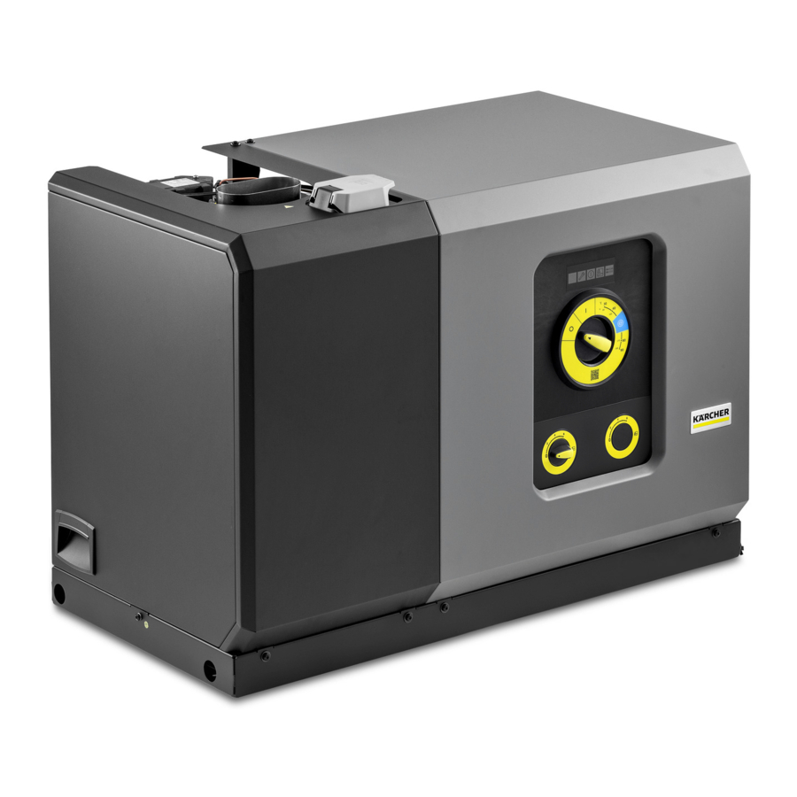
Description of the device
Illustration A

- Cover, left
- Filling point for system care
- Cover, right
- Control panel + electrical box
- Cover fastening screws, right
- Cover fastening screws, left
- Fuel filter
- Terminal box of motor
- Filling point for pump oil
- Fuel line (supply + return)
- Water inlet
- High-pressure outlet
- Pressure tank
- System care setting + service switch
- Fresh water filter
- Safety block
- Float tank with system care container
- Exhaust gas outlet
- Booster heater
The following attachment kits are available separately:
- Remote control (not shown)
- Pressure relief (not shown)
- Second detergent + dosage
- Steel floor structure (not shown)
- Water inlet solenoid valve (not shown)
- Operating hours counter + pressure gauge
Control panel
Illustration B

- Main switch
- Service menu indicator light (red)
- Service indicator light (red)
- Operation indicator light (green)
- Detergent indicator light (orange)
- System care indicator light (orange)
- Operating hours counter (option)
- Detergent dosing valve 2 (option)
- Pressure gauge (option)
- Detergent dosing valve 1
Meaning of the LED indicators
| Indicator light | Blink code | Meaning |
| Indicator light Service menu (red) | - | This indicator light is only relevant for service technicians. |
| Indicator light Service (red) | lights up | Carry out service/maintenance after 600 h pump operation after 400 h burner operation |
| flashes 1x | Leakage on the device The device switches off. | |
| flashes 2x | Current/voltage fault:
The device switches off. | |
| flashes 3x | Winding protection contact fault The device switches off. | |
| flashes 4x | Exhaust gas fault The device switches off. | |
| flashes 5x | Water shortage / dry running The device switches off. | |
| flashes 6x | Flame sensor LED too bright / too dark The device switches off. | |
| flashes 7x | Water outlet temperature sensor fault The device switches off. | |
| flashes 8x | Communication fault The device switches off. | |
| Indicator light Operation (green) | lights up | Normal operation without faults |
| flashes 1x | Pump has been running continuously for 30 minutes | |
| flashes 2x | Pump has been continuously inactive for 30 minutes | |
| Detergent indicator light (orange) | lights up | Detergent 1 empty |
| flashes 1x | Detergent 2 empty | |
| System care indicator light (orange) | lights up | System care empty |
High-pressure gun and lance (accessory)
Note
No accessories are included in the scope of delivery.
Illustration C

- Vibrasoft rotary nozzle
- Union nut
- High-pressure nozzle
- EASY!Lock spray lance
- Pressure/quantity regulation
- EASY!Force high-pressure gun
- Safety latch
- Trigger
- Safety lever
- EASY!Lock high-pressure hose
Functional description
- The cold water reaches the suction side of the high-pressure pump via the motor cooling coil and the float tank. System car (RM 110) is dosed into the float tank. Depending on the water hardness, this can be adjusted by customer service as required. The pump conveys water and detergent sucked in through the instantaneous water heater. The proportion of detergent in the water can be adjusted using a dosing valve. The instantaneous water heater is heated by a burner.
- The high-pressure outlet is connected directly to a high-pressure hose or to an existing high-pressure network in the building. The high-pressure gun is connected to the tapping points of this network using a high-pressure hose.
Flow chart

- Water inlet
- Water inlet solenoid valve (option)
- Electric motor
- Float tank
- High-pressure pump
- Check valve
- Safety valve
- Overflow valve
- Pressure switch
- Pressure tank for high pressure
- Water shortage safeguard
- Booster heater
- High-pressure outlet
- DGT container (system care)
- DGT solenoid valve (system care)
- Detergent check valve
- Dosing valve 1
- Solenoid valve for detergent 1 (option)
- Detergent inlet 1
- Dosing valve 2 (option)
- Solenoid valve for detergent 2 (option)
- Detergent inlet 2 (option)
- Pressure relief valve (option)
- Pressure gauge (option)
Water outlet temperature sensor T1
T4 exhaust gas temperature monitor
* Flow chart with 1 detergent without remote control (delivery status)
** Flow chart with 2 detergents and remote control (optional)
*** Flow chart with 1 detergent and remote control (optional)
System installation
Note
Installation may only be carried out by authorised specialist personnel!
General
- The heating equipment in the device is a firing system. The locally applicable regulations must be observed during installation.
- Only use tested chimneys and exhaust gas pipes.
Notes Oil installation
- When installing a fuel oil tank in the device installation room, observe the regulations on the storage of flammable liquids.
Fuel lines
Provide a two-pipe system with supply and return lines for the fuel lines.
- Maximum heating oil pre-pressure: 0.05 MPa (0.5 bar)
- Maximum negative pressure between heating oil filter and pump: 0.04 MPa (0.4 bar)
- Before the initial startup of the device, connect the external fuel lines to the device and supply them with fuel. This also applies to cold water operation, as otherwise the fuel pump will no longer be lubricated and will fail after a short time.
Air/exhaust gas routing
- The components for air/exhaust gas system are not included with the device. Observe the local regulations for building installation.
- Each device must be connected to its own chimney.
- Carry out the exhaust gas routing in accordance with local regulations and in consultation with the responsible chimney sweep.
Wall mounting
- Check the load capacity of the wall before installation. Use suitable plugs and screws for concrete, cavity block, brick and aerated concrete walls, e.g. an injection anchor.
- The device must not be rigidly connected to the water supply or high-pressure pipework. The connecting hoses must always be fitted.
- Provide a stopcock between the water pipe network and the connecting hose.
Installation of the high-pressure lines
Illustration E
Observe the relevant national regulations when installing the high-pressure lines.

- The pressure drop in the pipework must be less than 1.5 MPa.
- The finished pipework must be tested at 32 MPa.
- The insulation of the pipework must be temperature-resistant up to 100°C.
Setting up the detergent containers
- Set up the containers so that the lower level of the detergent is not more than 1.5 m below the base of the device and the upper level is not above the base of the device.
Remote control (option)
Remote controls can be connected between the device and the tapping points. These allow the device to be operated directly at the tapping point.
Various mounting kits for remote controls are available depending on the application.
| Function | Description | |
 | Reset | After the standby time has elapsed, the device can be restarted directly at the tapping point. |
 | Emergency off | |
 | On/Off + detergent (turn switch) Single workstation | Switching the device on and off at the tapping point. Activation of the hot water function (burner switches on). Selection of whether detergent should be added: No admixture, admixture RM 1 or admixture RM 2, as set on the device. |
 | On/Off + detergent (push buttons) up to 5 spots | Switching the device on and off at the tapping point. Activation of the hot water function (burner switches on). Selection of whether detergent should be added: No admixture, admixture RM 1 or admixture RM 2 (option), as set on the device. |
Water connection
Illustration D

- Connect the water inlet to the water pipe network using a suitable hose.
- The capacity of the water supply must be at least 1300 l/h at a minimum of 0.15 MPa.
- The water temperature must be under 30°C.
- If the "Solenoid valve water inlet" attachment kit is installed, the valve blocks the water inlet until water is required at a tapping point or the device is switched on.
Electrical connection
Note
Switch-on procedures will generate short-term voltage drops. Unfavourable mains conditions may cause other devices to be impaired.
 ATTENTION
Exceeding the grid impedance
Electrical shock in the event of a short-circuit
The maximum permissible mains grid impedance at the electrical connection point (see Technical data) must not be exceeded. Contact your electricity supplier in the case of any uncertainties regarding the mains grid impedance at your electrical connection point.
- For connected loads, see technical data and type plate.
- The electrical connection must be carried out by an electrician and comply with IEC 60364-1.
- All live parts, cables and devices in the work area must be in proper condition and be protected against water jets.

Danger of death from electric shock.
If the device is operated at a socket without an error current circuit breaker or without a protective contact (earthing), there is a danger of death from electric shock in the event of a fault! Only operate the device at sockets with an earthing contact and with an error current circuit breaker with a nominal fault current of max. 30 mA.
Mounting the high-pressure gun, spray lance, nozzle and high-pressure hose
Device with ANTI!Twist: Attach the yellow high-pressure hose connection to the high-pressure gun.
Note
The EASY!Lock system connects components quickly and safely via a single turn of the quick-release thread.
- Connect the spray lance to the high-pressure gun and handtighten (EASY!Lock).
Illustration G
![]()
- Plug the high-pressure nozzle onto the spray lance.
- Fit the union nut and hand-tighten (EASY!Lock).
- Device without a hose reel: Connect the high-pressure hose to the high-pressure gun and high-pressure connection of the device and tighten hand-tight (EASY!Lock).
- Device with a hose reel: Connect the high-pressure hose to the high-pressure gun and hand-tighten (EASY!Lock).

ATTENTION
Rolled-up high-pressure hose
Risk of damage
Fully unroll the high-pressure hose before starting operation.
Installation example

- Exhaust gas pipe
- Pipework with thermal insulation
- Reset button
- Control cabinet with multiple remote control
- Control cabinet with single remote control
- Remote control attachment kit (single) including emergency stop
- Connection point with stopcock and quick coupling
- Remote control attachment kit (multiple)
- Emergency stop button
- Hose reel
- Hose switch
- High-pressure hose
- Tapping point with high-pressure gun, spray lance and nozzle
- Supply water solenoid valve
- Water hose
- Heating oil tank
- Detergent tank
Startup

Risk of injury
Damaged components can lead to injuries when operating the device.
Check that the device, accessories, supply lines and connections are in perfect condition. Do not use the device if it is not in perfect condition.
- Ensure the water inlet is OK.
- Remove the detergent suction from the device.
- Connect the heating oil.
- Ensure the power supply is OK.
System care
Determining and setting the system care
Note
RM 110 prevents calcification of the heating coil, device and pipework in the presence of hard water.
| Water hardness (°dH) | Scale on the turn switch (1-10) | System care products to be used |
| <3 | 3 | RM 111 |
| 3...7 | 1 | RM 110 |
| 7...14 | 2 | RM 110 |
| 14...21 | 3 | RM 110 |
| >21 | 4 | RM 110 |
- Determine the local water hardness via the local supply company or with a hardness tester (order number 6.768-004.0).
- Set the system care dosage using the turn switch on the control panel.
Refilling the system care
- The system care is a highly effective agent for preventing calcification of the heating coil when operating with calcareous tap water. This is drip-fed dosed into the float container.
- The dosage is set to medium water hardness at the factory and can be adjusted to the water hardness on site if necessary.
- Refill the system care.
Operation
Standby mode
- If the high-pressure gun is closed during operation, the device will switch off.
- If the gun is opened again within the activatable standby time (30 minutes), the device restarts automatically.
- If the operating standby time is exceeded, the safety timer switches off the pump and burner.
- To restart the device, set the device switch to the "0" position, then switch it on again. If the device is controlled by a remote control, it can be restarted using the corresponding switch on the remote control.
Switch to standby mode
ATTENTION
Risk of injury
Risk of injury from escaping, possibly hot water stream!
Check the device for damage each time before use.
- Check the high-pressure hose, the pipework, the fittings and the spray lance for damage before each use.
- Replace leaking components immediately and seal leaking joints.
- Check the hose coupling for tight fit and leaks.
- Check the filling level of the detergent container and top up with detergent if necessary.
- Check the filling level of the system care and top up if necessary.
Nozzle selection

Risk of damage as a result of incorrect nozzle
Vehicle tyres can be damaged when cleaning with a round jet. Always clean vehicle tyres with a flat jet nozzle (25°) and a spray distance of at least 30 cm.
We recommend the following nozzles, depending on the device and the cleaning task:
| Nozzle | Spray angle | Pressure (MPa) |
| HDS 8/18-4 St | ||
| 043 | 40° | 18 |
| 043 | 25° | 18 |
| 043 | 0° | 18 |
| HDS 10/21-4 St | ||
| 050 | 40° | 21 |
| 050 | 25° | 21 |
| 050 | 0° | 21 |
| HDS 13/20-4 St | ||
| 070 | 40° | 20 |
| 070 | 25° | 20 |
| 070 | 0° | 20 |
Changing nozzles

Risk of injury!
Switch off the device and actuate the high-pressure gun until the device is depressurised before changing the nozzle.
- Secure the high-pressure gun by pushing the safety latch forwards.
- Change the nozzle.
Cold water operation
For removing light contamination and for rinsing, e.g. garden machines, terrace, tools.
- Set the power switch to "I".
Operation with hot water
Hot water
Risk of scalding
Avoid contact with hot water.
- Set the power switch to the desired temperature.
Eco level
The device works in the most economical temperature range (max. 60°C).
Operation with detergent
Risk of injury from detergent
Serious damage to health due to improper use of detergents.
Observe the detergent manufacturer's safety data sheet. Wear the prescribed personal protective gear.
Note
KÄRCHER detergents ensure fault-free operation. Ask us for advice, request our catalog or our detergent information sheets.
- Hang the detergent suction hose in a container with detergent.
- Set the detergent dosing valve to the desired dosage. The dosage is set in stages from 0 (no detergent) to 6 (highest dosage).
Recommended cleaning method
- Spray the detergent sparingly on the dry surface and let it work for a while (do not let it dry).
- Rinse off the loosened dirt with the high-pressure jet.
After operation with detergent
- Immerse the filter in clear water.
- Turn the dosing valve to the highest detergent concentration.
- Start the device and rinse clear for one minute.
Operation with detergent at the tapping point
As an alternative to dosing detergent at the device, detergent can also be added directly at the dispensing points.
Various options are available for this, e.g.a cup foam lance.
Risk of injury from detergent
Health risk due to incorrect handling of detergents. Adhere to the safety instructions stated on the detergent packaging.
ATTENTION
Risk of damage from unsuitable detergents
Using unsuitable detergents may damage the device and the item being cleaned.
Use only detergents approved by KÄRCHER. Observe the dosing recommendations and notes provided with the detergent.
Use detergents sparingly to help conserve the environment.
Note
KÄRCHER detergents ensure fault-free operation. Ask us for a consultation, request our catalogue or our detergent information sheets.
Illustration F

- Container
- Foam nozzle
- High-pressure gun
- Suction hose
- Gate
Detergent admixture: 3=high, 2=medium, 1=low
- Unscrew the container.
- Plug the desired gate into the suction hose.
- Fill the detergent into the container.
- Screw the container onto the foam nozzle.
- Disconnect the spray lance from the high-pressure gun.
- Connect the cup foam lance to the high-pressure gun and hand-tighten.
- Start up the high-pressure cleaner.
After operating with detergent
The cup foam lance must be flushed after use to prevent the formation of detergent deposits.
- Unscrew the container.
- Pour the remaining detergent back into the original packaging.
- Fill the container with clear water.
- Screw the container onto the cup foam lance nozzle.
- Operate the cup foam lance for approx. 1 minute to flush the detergent residue.
- Empty the container.
Opening/closing the high-pressure gun
- Actuate the safety lever and trigger. The high-pressure gun opens.
- Release the safety lever and trigger. The high-pressure gun closes.
Pressure/quantity regulator on the high-pressure gun
Danger of a loose spray lance
Risk of injury
Take care to ensure that the spray lance screw connection does not release when adjusting the pressure/quantity control.
- Set the power switch to max. 98°C.
- Adjust the working pressure and flow rate by turning (variable) the pressure/quantity regulator on the high-pressure gun (+/-).
Switching off the device
Danger of scalding from hot water
Contact with hot water can lead to scald injuries. After operation with hot water, the device must be operated with an opened gun with cold water for at least 2 minutes.
- Close the water inlet.
- Open the high-pressure gun.
- Switch on the pump with the power switch and let it run for 510 seconds.
- Close the high-pressure gun.
- Set the trigger to "0/OFF".
- Close the stopcock on the water inlet and, if necessary, also close other stopcocks at the tapping points
- Remove the water connection.
- Actuate the high-pressure guns at the tapping points until the system is depressurised.
- Lock the high-pressure guns by pushing the safety latch forwards.
Switching off in the event of an emergency
- Turn the main switch to position "0".
- Close the water inlet.
- Actuate the high-pressure gun until the device is completely depressurised.
Transport
Risk of injury, risk of damage
Be aware of the weight of the device during transportation.
- When transporting in vehicles, secure the device against slipping and tipping over according to the applicable guidelines.
Storage
Risk of injury or damage due to non-observance of the weight!
When transporting and storing the device, there is a risk of injury and damage due to its weight.
Take into account the weight of the device for transportation and storage, see chapter Technical data.
ATTENTION
Risk of damage due to frost!
Water that is not completely drained can damage the device and accessories during freezing.
Empty the water completely from the device and accessories.
Protect the device and accessories from frost.
Care and service
Service contract
We recommend that you choose a service contract to ensure reliable operation of the device. Please contact your KÄRCHER customer service department responsible.
Maintenance intervals
Daily
- Check the high-pressure gun.
- Check the mains cable.
- Check the filling level of the detergent containers.
- Check the filling level of the system care.
- Check the high-pressure hoses.
Weekly
ATTENTION
Risk of damage due to milky oil
Operation with milky oil can lead to damage to the device. If the oil is milky, inform the authorised Customer Service immediately.
- Check the system for leaks.
- Check the appearance and level of the pump oil.
- Check the vibration dampener.
Monthly
- Check the pump for leaks.
- Check the system for internal deposits. To do this, start up the system with a spray lance without a high-pressure nozzle. If the operating pressure on the device pressure gauge (optional) rises above 3 MPa, the system must be descaled.
- Clean the fresh water filter.
- Clean the fuel filter.
Every six months or after maintenance display on the device
- Change the oil in the high-pressure pump.
- Have the entire system checked and cleaned by customer service.
Annually
- Replace the fuel filter (earlier if necessary).
- Perform the safety test.
Every 5 years at the latest
- Perform the pressure test according to the manufacturer's specifications.
Maintenance work
Changing the oil
See the "Technical data" section for the oil volume and type.
- Provide a catch pan for approx. 1 litre of oil.
- Loosen the oil drain plug.
- Drain the oil into the catch pan.
Note
Dispose of the old oil in an environmentally friendly manner or hand it over to an authorised collection point. - Tighten the oil drain plug again.
- Slowly fill with new oil up to the centre of the sight glass or between the "Min" and "Max" markings on the dipstick.
Vent the device
- Switch the device on "I/ON".
- Unlock the lever of the high-pressure gun.
- Press the lever of the high-pressure gun. The device switches on.
- Allow the device for run a maximum of 2 minutes until the water escaping from the high-pressure gun is free of air bubbles.
- Release the lever of the high-pressure gun.
- Lock the lever of the high-pressure gun.
Cleaning the fresh water filters
- Close the water inlet.
- Release the screws of the cover and remove the cover.
- Unscrew the filter casing in front of the pump and remove the water filter.
- Clean the filter and replace if necessary
- Mount the device in reverse order.
Descale the device
Deposits accumulating in the pipework increase the flow resistance and the motor load becomes too high.
Hazard due to inflammable gases
Risk of explosion
Do not smoke during the descaling process. Ensure good ventilation.
Acid danger
Risk of acid burns
Wear safety goggles and protective gloves.
Execution:
According to legal regulations, only approved boiler solvents with a test certificate may be used for removing deposits.
- RM 101; Dissolves descaling and detergent residues.
- Fill a 20 litre container with 15 litres of water.
- Add 1 litre of scale solvent.
- Connect the water hose directly to the pump head and hang the free end into the container.
- Place the connected spray lance in the container without a nozzle.
- Start the motor according to the operating instructions of the motor manufacturer.
- Open the high-pressure gun and do not close it again during descaling.
- Set the temperature controller to a work temperature of 40°C.
- Let the device run until the work temperature is reached.
- Switch the device off and allow it to stand for 20 minutes. The high-pressure gun must remain open.
- Then pump the device empty.
Note
For the purposes of corrosion protection and neutralising acid residues, we recommend then pumping an alkaline solution (e.g. RM 81) through the device via the detergent container.
Frost protection
The device should be installed in a frost-protected room. If there is a risk of frost, e.g. when installed in an outside area, the device must be drained and flushed with antifreeze.
- Unscrew the water supply hose and the high-pressure hose.
- Allow the device for run for a maximum of 1 minute until the pump and lines are empty.
- Unscrew the supply line at the boiler base and allow the heating coil to drain.
- Pour a commercially available antifreeze into the float tank. Observe the handling instructions of the anti-freeze manufacturer when doing this.
- Place a catch pan under the high-pressure outlet.
- Switch on the device (without burner) until the device is completely flushed.
Note
The antifreeze also provides a certain degree of corrosion protection.
Troubleshooting guide
Inadvertently starting up device, touching live components
Risk of injury, electric shock
Switch off the device before performing any work on the device.
Remove the mains plug.
Have all checks and work on electrical parts performed by a qualified electrician.
In case of any malfunctions not mentioned in this chapter, contact the authorised Customer Service.
Who is permitted to eliminate faults?
Operator: Work labelled with "Operator" may only be performed by instructed persons capable of operating and maintaining highpressure systems.
Qualified electrician: Work labelled with "Electrician" may only be performed by qualified electricians.
Customer Service: Work labelled with "Customer service" may only be performed by KÄRCHER customer service technicians or KÄRCHER-authorised technicians.
Troubleshooting guide
| Fault | Cause | Rectification | Person responsible |
Device is not running | There is no voltage in the machine. |
| Operator, qualified electrician |
| Safety timer active. |
| Operator | |
| Fuse blown in the control circuit. |
| Customer Service department | |
| HP pressure switch (high pressure) faulty. |
| Customer Service department | |
| Burner does not ignite or flame goes out during operation | Temperature controller set too low. |
| Operator |
| Power switch is not set to warm water. |
| Operator | |
| Low water cut-out in the safety block has switched off (Service indicator light flashes 5x). |
| Operator | |
| No fuel. |
| Operator | |
| Exhaust gas thermostat has triggered (Service indicator light flashes 4x) |
| Operator | |
| Malfunction occurs repeatedly. |
| Operator | |
Service indicator light flashes 1x | Leak in the high-pressure system. |
| Operator |
Service indicator light flashes 2x | Fault in the voltage supply or current consumption of the motor too high. |
| Operator |
Service indicator light flashes 3x | Motor overloaded or overheated. |
| Operator |
| Malfunction occurs repeatedly. |
| Customer Service | |
Service indicator light flashes 4x | Exhaust gas thermostat has triggered. |
| Operator |
| Malfunction occurs repeatedly. |
| Customer Service | |
Service indicator light flashes 5x | Water shortage. |
| Operator |
| Reed switch stuck in the water shortage safeguard or magnetic piston stuck. |
| Customer Service | |
The service indicator light flashes 6x | Flame sensor has switched off the burner. |
| Customer Service |
Service indicator light flashes 7x | Water outlet temperature sensor fault. |
| Customer Service |
| Service indicator light flashes 8x | Communication fault. |
| Customer Service |
Service indicator light lights up | Maintenance required. The device continues running. |
| Customer Service department |
Insufficient or no detergent delivery | Dosage set too low. |
| Operator |
| Detergent filter clogged or tank empty (detergent LED lights up or flashes). |
| Operator | |
| Detergent suction hoses, dosing valve or solenoid valve leaking or blocked. |
| Operator, customer service | |
| Malfunction occurs repeatedly. |
| Operator | |
System care LED lights up | System care used up. |
| Operator |
Pump not reaching the required pressure | Flushed the nozzle. |
| Operator |
| Detergent tank is empty. |
| Operator | |
| Not enough water. |
| Operator | |
| Fresh water filter contaminated. |
| Operator | |
| Detergent dosing valve is leaking. |
| Operator | |
| Detergent hoses are leaking. |
| Operator | |
| Float valve is jammed. |
| Operator | |
| Safety valve is leaky. |
| Customer Service department | |
| Flow control valve is leaking or set too low. |
| Customer Service department | |
| Solenoid valve for pressure relief is defective. |
| Customer Service department | |
| High-pressure pump knocking, pressure gauge fluctuates greatly | Vibration dampener is defective. |
| Customer Service department |
| High-pressure pump draws in a small amount of air. |
| Customer Service department | |
| Detergent container empty and detergent dosing activated. |
| Operator | |
| Not enough water, water inlet/fresh water filter blocked. |
| Operator | |
| The device keeps turning on and off when the high-pressure gun is open. | Nozzle in the spray lance is clogged. |
| Operator |
| Device is scaled. |
| Operator/customer service | |
| The switching point of the overflow valve has become misaligned. |
| Customer Service department | |
| The device does not switch off when the high-pressure gun is closed | Air in the pump. |
| Operator |
| Safety valve or safety valve seal is defective. |
| Customer Service | |
| Pressure switch faulty. |
| Customer Service |
Technical data
| HDS 8/18-4 St | HDS 10/21-4 St | HDS 13/20-4 St | ||
| Electrical connection | ||||
| Mains voltage | V | 400 | 400 | 400 |
| Phase | ~ | 3 | 3 | 3 |
| Power frequency | Hz | 50 | 50 | 50 |
| Power rating | kW | 5,5 | 8 | 9,5 |
| Power protection (C-type, gL/gG) | A | 16 | 25 | 25 |
| Degree of protection | IPX5 | IPX5 | IPX5 | |
| Protection class | I | I | I | |
| Maximum permissible mains grid impedance | Ω | 0,0607 | ||
| Water connection | ||||
| Input amount (min.) | l/h (l/min) | 1000 (16,7) | 1300 (21,7) | 1500 (25) |
| Feed pressure (max.) | MPa (bar) | 1 (10) | 1 (10) | 1 (10) |
| Input temperature (max.) | °C | 30 | 30 | 30 |
| Device performance data | ||||
| Water flow rate | l/h (l/min) | 800 (13,3) | 1000 (16,7) | 1300 (21,7) |
| Water operating pressure with standard nozzle | MPa (bar) | 18 (180) | 21 (210) | 20 (200) |
| Excess operating pressure safety valve (maximum) | MPa (bar) | 21,5 (215) | 23,5 (235) | 23,5 (235) |
| Hot water operating temperature (maximum) | °C | 98 | 98 | 98 |
| Detergent flow rate | l/h (l/min) | 0-45 (0-0,75) | 0-58 (0-0,97) | 0-45 (0-0,75) |
| Burner output | kW | 61 | 77 | 108 |
| Total water temperature increase under full load | K | 65 | 65 | 65 |
| Heating oil consumption (max.) | kg/h | 5,1 | 6,5 | 9,1 |
| High-pressure gun recoil force | N | 65 | 57 | 72 |
| Nozzle size of standard nozzle | 043 | 050 | 070 | |
| Dimensions and weights | ||||
| Typical operating weight | kg | 134 | 143 | 168 |
| Length | mm | 1141 | 1141 | 1141 |
| Width | mm | 577 | 577 | 577 |
| Height with chimney adapter | mm | 936 | 936 | 940 |
| High-pressure pump | ||||
| Filling quantity | l | 0,5 | 0,65 | 0,65 |
| Oil type | SAE 15W-40 | SAE 15W-40 | SAE 15W-40 | |
| Burner | ||||
| Fuel | EL heating oil or diesel | EL heating oil or diesel | EL heating oil or diesel | |
| Determined values in acc. with EN 60335-2-79 | ||||
| Sound pressure level LpA | dB(A) | 78 | 78 | 78 |
| Uncertainty KpA | dB(A) | 3 | 3 | 3 |
| Sound power level LWA + uncertainty KWA | dB(A) | 95 | 95 | 95 |
| Hand-arm vibration value | m/s2 | 3,9 | 3,8 | 4,8 |
| Uncertainty K | m/s2 | 0,9 | 1,3 | 1 |
Exception according to Regulation (EU) 2019/1781 Annex I Section 2 (12): j)
Subject to technical changes without notice.
Dimension sheet HDS 8/18-4 ST+HDS 10/21-4 ST

Dimension sheet HDS 13/20-4 ST

General notes

Read these original operating instructions and the enclosed safety instructions before using the device for the first time. Proceed accordingly. Keep both books for future reference or for future owners.
Safety instructions
- No changes may be made to the device.
- Exhaust gases are toxic. Never breathe in the exhaust gases. Ensure rooms where the device is operated are sufficiently ventilated and that exhaust gases can be conducted away.
Note
- Observe the respectively applicable national regulations for liquid jet cleaners.
- Observe the legislature's national accident prevention regulations. Liquid jet cleaners must be tested regularly and the results of the test recorded in writing.
- Observe the safety instructions of the used the detergents.
- Note that the heating system in the device is classified as a furnace. Furnaces must be inspected regularly according to the applicable national regulations.
- According to the applicable national regulations, this high-pressure cleaner must be initially commissioned by a qualified person when used commercially. KÄRCHER has already performed and documented this initial commissioning for you. You can request the documentation for this from your KÄRCHER partner. Please provide the part number and works number of the device when requesting documentation.
- We explicitly state that the application national regulations require that this device must be inspected regularly by a qualified person. Please contact your KÄRCHER partner for this.
Symbols on the device
 | Do not point the high-pressure jet at people, animals, live electrical equipment or at the device itself. Protect the device from frost. |
 | Danger of injury from electrical voltage. Only qualified electricians or authorised and qualified technical specialists are permitted to work on the electrical systems. |
 | According to applicable regulations, the device must never be used with the drinking water network without a system separator. Ensure that the connection to your house water system, with which the high-pressure cleaner is operated, is equipped with a system separator according to EN 12729 type BA. Water that has flowed through a system separator is classified as undrinkable. Always connect the system separator to the water supply and never directly to the device. |
 Health risk from poisonous exhaust gases. Never inhale the exhaust gases.
 Risk of burns from hot surfaces.
 | Code for information |
Regulations, guidelines and standards
The gas supply company and the district chimney sweep should be consulted before the device is installed.
The regulations of building law, commercial law and emissions protection law must be observed during installation. We draw your attention to the regulations, directives and standards listed below:
- The device may only be installed by a specialised company in accordance with the relevant national regulations.
- The respective national regulations set by the legislator must be observed during the electrical installation.
- Adjustments, maintenance work and repairs to the burner may only be carried out by trained Kärcher service technicians.
- The locally applicable regulations must be adhered to when planning a chimney.
Workstation
The device is used to switch the system on and off and to set the water temperature. The detergent dosage can also be set and error messages can be viewed.
Depending on the system design, further workstations are located at the accessory devices (spraying devices), which are connected to the tapping points. Remote controls can optionally be installed at these workstations.
Safety devices
Risk of injury due to missing or modified safety devices!
Safety devices are provided for your own protection.
Do not bypass, remove or render ineffective any safety devices. The safety devices are set and sealed by the manufacturer. Adjustments are performed only by customer service.
Water shortage safeguard
The water shortage safeguard (flow switch) prevents the burner from overheating and dry running of the HP-pump in the case of a water shortage. If the water supply is insufficient, the device switches off.
Pressure switch
The pressure switch switches the device off if the maximum working pressure is exceeded.
Safety valve of safety block
If the maximum permissible system pressure is exceeded, the safety valve opens to relieve the pressure in the system. The safety valve is adjusted and sealed at the factory. The adjustment is performed only by customer service.
Flame monitoring
The flame monitoring system monitors the brightness of the flame on the burner and switches the burner off in the event of a fault.
Overcurrent protection
The motor of the high-pressure pump is protected by the electronics and a winding circuit breaker.
Exhaust gas thermostat
If the emission temperature rises above the permissible value, the emission temperature limiter switches the burner off and locks it.
Temperature limiter
The temperature limiter switches the burner off when the temperature is too high.
Air pressure switch
The air pressure switch switches off the burner as soon as the fan fails to generate air pressure.
Emission pressure switch
The emission pressure switch switches off the burner if an impermissibly high back pressure is created in the emission system, e.g. in the event of a blockage.
Pressure relief of high pressure system (option)
After switching off the device via the high-pressure gun, a solenoid valve located in the high-pressure system opens after the operating standby time has elapsed. This reduces the pressure built up in the high-pressure system.
Safety latch
The safety catch on the high-pressure gun prevents the device from being switched on inadvertently.
Readiness time
If the device is not used for 30 minutes, the device switches off. The readiness time can be activated and deactivated by customer service via the service menu.
Intended use
- The device is used to remove dirt from surfaces using a freeflowing water stream. It is used in particular for cleaning machines, vehicles and facades.
- The system must be installed so that the rear opening is closed, for example by a wall.
- Only clean water may be used as a high-pressure medium. Contamination leads to premature wear and tear or deposits in the device.
Use at petrol stations or other hazard zones
Risk of injury
Adhere to the respective safety regulations.
Note
Do not allow waste water containing mineral oil to penetrate soil, waterways or the sewage system. Only wash the motor or the undercarriage in suitable places with an oil separator.
Water supply limit values
ATTENTION
Dirty water
Premature wear and tear or deposits in the device Supply the device using only clean water, or recycled water that does not exceed the specified limit values.
The following limit values apply to the water supply:
- pH value: 6.5-9.5
- Electrical conductivity: Conductivity of fresh water + 1200 µS/ cm, maximum conductivity 2000 µS/cm
- Settleable particles (sample volume 1 l, settling time 30 minutes): < 0.5 mg/l
- Filterable particles: < 50 mg/l, no abrasive substances
- Hydrocarbons: < 20 mg/l
- Chloride: < 300 mg/l
- Sulphate: < 240 mg/l
- Calcium: < 200 mg/l
- Total hardness: < 28 °dH, < 50° TH, < 500 ppm (mg CaCO3/l)
- Iron: < 0.5 mg/l
- Manganese: < 0.05 mg/l
- Copper: < 2 mg/l
- Active chloride: < 0.3 mg/l
- Free of unpleasant odours
Documents / Resources
References
Download manual
Here you can download full pdf version of manual, it may contain additional safety instructions, warranty information, FCC rules, etc.
Download Kärcher HDS 8/18-4 ST, HDS 10/21-4 ST, HDS 13/20-4 ST Manual
Advertisement


Need help?
Do you have a question about the HDS 8/18-4 ST and is the answer not in the manual?
Questions and answers