
Subscribe to Our Youtube Channel
Related Manuals for Kärcher HDS Series


Summary of Contents for Kärcher HDS Series
- Page 1 OPERATOR’S MANUAL HDS, LFT SERIES English Hot Water - Gas Powered - Diesel Heated ® Register 9.808-341.0-E 12/19/22 your product www.kaercher.com/welcome...
-
Page 2: Machine Data Label
Machine Data Label MODELS: HDS 5.0/40 LFT 1.110-101.0 HDS 8.0/30 LFT 1.110-102.0 HDS 5.0/35 LFT 1.110-103.0 HDS 8.0/30 LFT 1.110-104.0 9.808-341.0 - E - Operator's Manual, LFT... -
Page 3: Table Of Contents
Table of Contents Machine Data Label ......2 Wayne Burner EHASR - AC ....47 KT.2 Series Pump. -
Page 4: How To Use This Manual
How To Use This Manual This manual contains the following sections: The MAINTENANCE section contains preventive main- tenance to keep the machine and its components in • How to Use This Manual good working condition. They are listed in this general •... -
Page 5: Safety
Safety Introduction & Safety Information Thank you for purchasing this Pressure Washer. We reserve the right to make changes at any time without incurring any obligation. Owner/User Responsibility: The owner and/or user must have an understanding of the manufacturer’s operating instructions and warnings before using this pressure washer. -
Page 6: Important Safety Information
Safety Important Safety Information des mains et des pieds doit être portée lors de l'utilisation de cet équipement. projection à hautes WARNING: To reduce the risk of vitesses. WARNING injury, read operating instructions 5. Always wear properly rated eye protection such as carefully before using. - Page 7 Safety b. with the engine on the equipment stopped; cela risquerait de causer des blessures graves ou with no source of ignition within 10 feet of the même la mort. dispensing point; and WARNING: This machine produces d. with an allowance made for expansion of the fuel WARNING hot water and must have insulated should the equipment be exposed to a higher...
- Page 8 Safety WARNING: Protect machine from 22. Never run pump dry or leave spray gun closed WARNING longer than 1-2 minutes. freezing. AVERTISSEMENT: Protéger la 23. Machines with shut-off spray gun should not be machine contre le gel. operated with the spray gun in the off position for extensive periods of time as this may cause 1.
-
Page 9: Operations
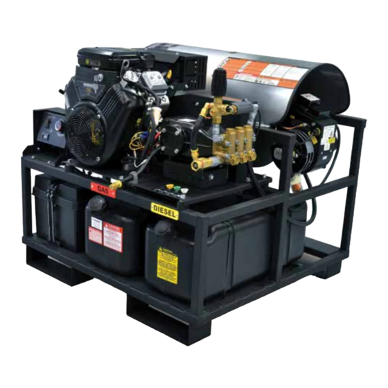
Operations Component Identification Flue Adapter Optional 7-10049 Insulation Gasket Optional 7-01471 Water Supply Hose (not included) Detergent Valve Unloader Valve 22mm Pump Coupling Outlet Adjustable Thermostat Burner Switch Hour Meter Trigger Wand Spray Gun High Pressure Hose Pump — Delivers a specific gpm to the high pressure Adjustable Thermostat —... -
Page 10: Assembly Instructions
Operations Assembly Instructions Safety Latch Cold Spray Water Source Wand High Pressure Hose Garden Hose STEP 1: Attach wand and hose to STEP 2: Connect garden hose to STEP 3: Remove shipping cap and the spray gun using teflon tape on the cold water source. -
Page 11: Battery Installation
Operations Battery Installation Due to Federal Regulations concerning shipment of corrosive chemicals, batteries are not shipped with this machine. Local purchase of battery will be the responsibility of the owner. Automotive type 12 Volt Group 24 battery is recom- mended for placement within the weather resistant box. Follow safety and installation instructions furnished with the battery. -
Page 12: Operating Instructions
Operations Operating Instructions Dipstick Tank STEP 2: Fill gas tank with unleaded gasoline. Do not use leaded STEP 1: Check engine oil level. Oil level should be level to the fill markings gasoline. on the dipstick. Be sure the machine is level when checking the oil level. (Refer to the engine's operating manual included with machine.) We recommend that the oil be changed after the first 5 hours of use, then once every 100 hours. - Page 13 AVERTISSEMENT: Le retour du cordon de lancement (rétraction rapide) peut causer des lésions corporelles. La rétraction rapide de la corde du démarreur (recul) attire la main et le bras vers le moteur plus vite qu'il n'est possible de lâcher la corde. Toujours réduire la pression du pistolet pulvérisateur avant de tirer sur le START cordon de lancement.
-
Page 14: Detergents & General Cleaning Techniques
Operations Detergents & General Cleaning needed, use brush to remove stubborn dirt. Rinse at high pressure from top to bottom in an even sweeping motion Techniques keeping the spray nozzle approximately 1 foot from WARNING: Some detergents may cleaning surface. Use overlapping strokes as you clean WARNING be harmful if inhaled or ingested, and rinse any surface. -
Page 15: Shutting Down And Clean Up
Operations Shutting Down And Clean Up On-Off Switch STEP 2: Turn off the engine. STEP 3: Turn off water supply. STEP 1: Remove detergent suction tube from container and insert into one gallon of fresh water. Open detergent metering valve. Pull trigger on spray gun and siphon water for one minute. -
Page 16: Maintenance
Maintenance Storage tank of the engine, or to the gasoline in a storage container. CAUTION: Always store your pressure washer in a location where the temperature will not fall below After Extended Storage 32°F (0°C). The pump in this machine is susceptible to permanent damage if frozen. -
Page 17: Maintenance And Service
Maintenance Pumps It is advisable, periodically, to visually inspect the burner. Check air inlet to make sure it is not clogged or Before running the pump check the pump crankcase for blocked. Wipe off any oil spills and keep equipment a proper oil level. -
Page 18: Fuel
Maintenance Fuel Also, as ambient temperature changes seasonally, the fuel temperature in the feed tank and air temperature Use clean fuel oil that is not contaminated with water inlet can impact fuel flow. In more extreme tempera- and debris. Replace fuel filter and drain tank every 100 tures, this local-site adjustment may also require hours of operation. -
Page 19: Burner Air Adjustment
Maintenance Burner Air Adjustment Coil Removal The oil burner on this machine is preset for operation at Removal of coil because of freeze breakage, or to altitudes below 500 feet. If operated at higher altitudes, clean soot from it can be done quickly and easily. it may be necessary to adjust the air band for a #1 or #2 1. -
Page 20: Preventive Maintenance
Maintenance Preventive Maintenance This pressure washer was produced with the best available materials and quality craftsmanship. However, you as the owner have certain responsibilities for the correct care of the equipment. Attention to regular preventative main- tenance procedures will assist in preserving the performance of your equipment. Contact your dealer for mainte- nance. -
Page 21: Oil Change Record
Maintenance Oil Change Record PUMP OIL Estimated Operating ENGINE OIL Estimated Operating Date Oil Changed Hours Since Last Oil Date Oil Changed Hours Since Last Oil Month/Day/Year Change Month/Day/Year Change 9.808-341.0 - E - Operator's Manual, LFT... -
Page 22: Troubleshooting
Maintenance Troubleshooting PROBLEM SOLUTION POSSIBLE CAUSE Faulty pressure gauge Install new gauge. Insufficient water supply Use larger supply hose; clean filter at water inlet. Match nozzle number to machine and/or replace Old, worn or incorrect spray nozzle with new nozzle. Belt slippage Tighten or replace;... - Page 23 Maintenance PROBLEM SOLUTION POSSIBLE CAUSE Flex coupling slipping on fuel Replace if needed. pump shaft or burner motor shaft Check for electrical current reaching burner assembly On-Off switch defective with burner switch on. Heavy sooting on coil and burner can cause interruption of air flow Clean as required.
- Page 24 Maintenance SOLUTION PROBLEM POSSIBLE CAUSE Improper fuel or water in fuel Replace with clean and proper fuel. Low fuel pressure Increase fuel pressure. Check fuel pump pressure. Replace pump if Weak fuel pump needed. WATER Fuel filter partially clogged Replace as needed. TEMPERATURE Soot build-up on coils not allowing Clean coils.
- Page 25 Maintenance PROBLEM POSSIBLE CAUSE SOLUTION Oil seal worn Check and replace if necessary. DRIPPING EXCESSIVE VIBRATION IN Irregular functioning of the valves Check and replace if necessary. DELIVERY LINE Tighten all clamps. Check detergent lines for Air leak holes. Replace restrictor. Check for proper orifice in Restrictor in float tank is missing restrictor.
- Page 26 Notes 9.808-341.0 - E - Operator's Manual, LFT...
-
Page 27: Parts
Parts Parts LFT HDS HDS 5.0/40 LFT 1.110-101.0 HDS 8.0/30 LFT 1.110-102.0 HDS 5.0/35 LFT 1.110-103.0 HDS 8.0/30 LFT 1.110-104.0 9.808-341.0 - E - Operator's Manual, LFT... -
Page 28: Karcher Hds
LFT HDS See Engine Assy For Details 9.808-341.0 - E - Operator's Manual, LFT... - Page 29 LFT HDS 9.808-341.0 - E - Operator's Manual, LFT...
- Page 30 LFT HDS PART NO. DESCRIPTION NOTES 8.930-782.0 FRAME ENTRY LEVEL SKID BLACK WELDMENT, BOTTOM WRAP, BLACK, SUPER 9.803-006.0 SKID 9.803-014.0 COIL, (RODLESS) TUFF 9.803-005.0 TOP WRAP, TUFF, SS 9.802-883.0 INSULATION, BURNER HEAD, NO HOLE 9.802-894.0 INSULATION, BURNER HEAD, W/HOLE 8.747-405.0 NIPPLE, 1/2"...
- Page 31 LFT HDS PART NO. DESCRIPTION NOTES 8.715-592.0 PULLEY 2BK80H (1.110-102.0,1.110-103.0) 9.802-384.0 PULLEY, 2BK 32 H (1.110-101.0) 9.802-383.0 PULLEY, 2BK 36 H (1.110-102.0) 8.715-576.0 PULLEY, 2BK 40H (1.110-103.0) 9.802-735.0 BOLT, 3/8" X 5-1/2", NC HH TAP 9.802-716.0 BOLT, 5/16 X 2", NC HH 8.718-980.0 WASHER, 5/16"...
-
Page 32: Pump Leuco Lt6036R
Pump Leuco LT6036R 8.930-831.0 for model 1.110-103.0 17 10 9.808-341.0 - E - Operator's Manual, LFT... - Page 33 Pump Leuco LT6036R PART NO. DESCRIPTION NOTES 8.705-119.0 HOSE BARB, ELBOW, 3/8"BARBX3/8"MPT/90DEG 8.705-120.0 HOSEBARB, ELBOW, 3/8"BARBX1/2"MPT/90DEG 8.707-254.0 PUMP PROTECTOR , 3/8" 145 DEG 8.711-785.0 HOSE, 3/8" PUSH-ON, RETURN HOSE 8.716-125.0 SWITCH,PRESSURE,3/8" BSP BRASS, 65" 8.750-299.0 UNLOADER, VRT3, 8 GPM @4500 PSI 8.756-874.0 ADAPTER STEEL 1/2 NPTF(F) X 1/2 BSPP(M) 8.757-203.0...
-
Page 34: Pump Leuco 9536R
Pump Leuco 9536R 8.930-857.0 for model 1.110-102.0 9.808-341.0 - E - Operator's Manual, LFT... - Page 35 Pump Leuco 9536R PART NO. DESCRIPTION NOTES FILTER SCREEN WASHER, GARDEN HOSE/ 9.804-016.0 30MESH 9.802-259.0 13” HOSE, 1/2" PUSH-ON, DRAIN HOSE 9.802-151.0 SWIVEL, 1/2" BARB X 1/2"JIC, FEM/BRASS 9.802-126.0 PLUG, 1/2" JIC FLARE, 639F-8 8.931-300.0 PUMP ASSEMBLY GENERIC LX9536R.2 8.918-427.0 HOSE, 3/8"...
-
Page 36: Pump Leuco 584R
Pump Leuco 5843R 8.931-564.0 for model 1.110-101.0 9.808-341.0 - E - Operator's Manual, LFT... - Page 37 Pump Leuco 5843R PART NO. DESCRIPTION NOTES 8.705-119.0 HOSE BARB, ELBOW, 3/8"BARBX3/8"MPT/90DEG 8.705-120.0 HOSEBARB, ELBOW, 3/8"BARBX1/2"MPT/90DEG 8.707-254.0 PUMP PROTECTOR , 3/8" 145 DEG 8.711-785.0 HOSE, 3/8" PUSH-ON, RETURN HOSE 8.716-125.0 SWITCH,PRESSURE,3/8" BSP BRASS, 65" 8.750-299.0 UNLOADER, VRT3, 8 GPM @4500 PSI 8.750-933.0 HOSE BAND CLAMP HOSE ID 1/8"...
-
Page 38: Engine Gasoline Tank
Engine Gasoline Tank (To Tank) (To Engine Purge) 9.808-341.0 - E - Operator's Manual, LFT... - Page 39 Engine Gasoline Tank PART NO. DESCRIPTION NOTES 8.752-916.0 TANK, GASOLINE, 11.5 GAL 9.802-254.0 45" HOSE 1/4" PUSH-ON 9.802-770.0 SCREW 1/4" BH 9.802-773.0 1/4" LOCKNUT 9.802-254.0 10" HOSE, 1/4" FUEL 6.390-126.0 CLAMP, HOSE, .46 - .54 ST 8.709-152.0 FILTER, FUEL DISPOSABLE 9.802-056.0 DIP TUBE ASSY, PLASTIC 10.75"...
-
Page 40: Burner Fuel Oil Tank
Burner Fuel Oil Tank Inlet to Burner Return Line from Burner PART NO. DESCRIPTION NOTES 8.752-189.0 TANK, DIESEL, 11.5 GAL 9.802-056.0 DIP TUBE ASSY, PLASTIC, 10.75" LONG 8.750-933.0 BAND HOSE CLAMP, HOSE ID 1/8" - 5/16" 9.802-254.0 36" HOSE, 1/4" PUSH-ON, FUEL 9.802-053.0 BUSHING MOLDED 9.803-535.0... -
Page 41: Control Panel
Control Panel 19 20 PART NO. DESCRIPTION NOTES 8.716-223.0 HOLDER, FUSE 9.803-249.0 SCREW, M4 X 10 9.802-064.0 GROMMET, RUBBER NOZZLE HOLDER 9.802-762.0 SCREW, 10/32" X 1-1/41 8.706-745.0 PLUG, PLASTIC 9.802-700.0 BOLT, 1/4" X 3/4" NC HH 9.802-480.0 BOX, PLASTIC, BACK 9.802-514.0 STRAIN RELIEF, STRAIGHT, LQ TITE 8.750-095.0... - Page 42 Control Panel PART NO. DESCRIPTION NOTES 8.752-804.0 REGULATOR, 12 VOLT DC 9.802-470.0 RELAY, 12V, VF4A-45-H11 24V/40A 8.719-947.0 BOX, PLASTIC FRONT, 2 SQUARE HOLES 8.900-924.0 LABEL, 1200SSG, CONTROL BOX 9.802-771.0 SCREW, 10/32" X 3/4" BH SOC CS 9.802-283.0 HOUR METER, 120V 9.802-451.0 SWITCH, ROCKER, CARLING W/GREEN LENS 8.712-190.0...
-
Page 43: Hose & Spray Gun
Hose & Spray Gun PART NO. DESCRIPTION NOTES 8.925-132.0 HOSE, 3/8" X 50' 2W 6000PSI SW/SO/CPL (1.110-103.0,1.110-101.0 ) 8.925-245.0 HOSE, 1/2"X50' 2W 5000PSI KAR SW,SO,CPL (1.110-104.0, 1.110-102.0) 8.710-384.0 GUN, ST-1500, 5000 PSI, 10.4 GPM 8.759-393.0 LANCE 44" 8.712-356.0 NOZZLE, SAQCMEG 4005, WHITE 1.110-101.0 8.712-355.0 NOZZLE, SAQCMEG 2505, GREEN... -
Page 44: Specifications
Specifications Wayne EHASR Burner BURNER Burner Part Fuel Nozzle MODEL NO. Fuel Nozle NUMBER Part # BURNER, EHASR 12VDC DO 2T FUEL NOZZLE 1.110-101.0 8.756-480.0 8.700-947.0 12VDC S 2.50 X 80 B BURNER , EHASR 12VDC DO 2T FUEL NOZZLE 1.110-102.0 8.756-890.0 8.700-947.0... -
Page 45: Wayne Burner - Dc
Wayne Burner EHASR - DC 9.808-341.0 - E - Operator's Manual, LFT... - Page 46 Wayne Burner EHASR - DC PART NO. DESCRIPTION NOTES 8.756-716.0 MOTOR, 1/4 13.5VDC AMETEK 13121 MOTOR CORD COVER 8.756-726.0 FAN, 3.44"W X 5.25"D 5/16" BORE 8.700-735.0 BURNER HOUSING EHASR 9.107-507.0 IGNITOR 13392 SLOT COVER PLATE 8.700-732.0 BAND, AIR BURNER INNER EHA/SR 8.700-729.0 AIR BAND 8 HOLE OUTER EHA/SR 8.756-715.0...
-
Page 47: Wayne Burner Ehasr - Ac
Wayne Burner EHASR - AC PART NO. DESCRIPTION NOTES 8.756-436.0 MOTOR, 1/4 HP, 120VAC 13121 MOTOR CORD COVER 8.756-438.0 FAN - 6 1/4” DIA 8.700-735.0 BURNER HOUSING PAINTED 8.700-802.0 IGNITOR, E, 120VAC 13392 SLOT COVER PLATE 8.700-732.0 BAND, AIR BURNER INNER EHA/SR 8.700-729.0 AIR BAND 8 HOLE OUTER EHA/SR 8.700-776.0... -
Page 48: Kt.2 Series Pump
KT.2 Series Pump TORQUE SPECS ITEM # FT. LBS. PART NO. DESCRIPTION NOTES 8.752-825.0 CRANKCASE PLUNGER OIL SEAL SEE KITS TABLE O-RING Ø1.78 X 37.82 SEE KITS TABLE PRESSURE RING, 18MM SEE KITS TABLE U-SEAL, 18MM SEE KITS TABLE INTERMEDIATE RING, 18MM SEE KITS TABLE U-SEAL, 18MM SEE KITS TABLE... - Page 49 KT.2 Series Pump PART NO. DESCRIPTION NOTES VALVE SPRING SEE KITS TABLE VALVE CAGE SEE KITS TABLE 8.752-830.0 HEX SCREW 9.802-884.0 WASHER 9.803-182.0 CLOSED BEARING HOUSING 9.803-186.0 O-RING Ø2.62 X 71.12 9.803-160.0 ROLLER BEARING 8.753-818.0 CRANKSHAFT Ø25 (4540) 8.752-827.0 CRANKSHAFT Ø25 (6036) 9.803-167.0 CRANKSHAFT KEY 8.752-834.0...
-
Page 50: Vrt3 Unloader
VRT3 Unloader 8.750-297.0, 8 GPM, 2320 PSI 8.750-298.0, 8 GPM, 3630 PSI 8.750-299.0, 8 GPM, 4500 PSI PART NO. DESCRIPTION NOTES 8.750-713.0 OUTLET FITTING 8.750-712.0 KNOB, UNLOADER 8.750-709.0 REPAIR KIT, VRT3, 2320/3630 PSI 8.750-710.0 REPAIR KIT, VRT3, 4500 PSI (KIT ITEMS: 3, 4, 6, 9-12, 21, 24) 9.808-341.0 - E - Operator's Manual, LFT... -
Page 51: Loncin Engine - Steps
VRT3 Unloader Unloader Adjustment Procedures 1. Remove lock nut (Item 19). 2. Remove adjustment knob (Item 18). 3. Loosen the two (2) nuts (Item 15), move them upward on stem (Item 8) until you see 4 or more threads below the nut. - Page 52 Loncin Engine - Steps FOR LONCIN ENGINES ONLY TO ASSEMBLE AIR CLEANER FOLLOW THE NEXT STEPS: STEP 1: Place the air filter on top of the STEP 2: Fasten the following screws engine. (2):6x12 *Included with machine. STEP 3: Connect both hoses, add clamp. STEP 4: Fasten the following screws *Included with machine.
- Page 53 Loncin Engine - Steps STEP 5: Connect hose from canister. 9.808-341.0 - E - Operator's Manual, LFT...
- Page 54 Karcher North America 6398 N Kärcher Way, Aurora, CO 80019 Form #9.808-341.0 • Revised 11/22 • Printed in U.S.A. or Mexico...
Need help?
Do you have a question about the HDS Series and is the answer not in the manual?
Questions and answers