ekwb EK-Quantum Vector3 FE RTX 5090 User Manual
Gpu water block
Hide thumbs
Also See for EK-Quantum Vector3 FE RTX 5090:
- User manual (17 pages) ,
- User manual (17 pages) ,
- User manual (18 pages)
Table of Contents
Advertisement
Quick Links
Advertisement
Table of Contents

Related Manuals for ekwb EK-Quantum Vector3 FE RTX 5090


Summary of Contents for ekwb EK-Quantum Vector3 FE RTX 5090
- Page 1 EK-Quantum Vector3 FE RTX 5090 GPU WATER BLOCK - 1 - USER GUIDE...
- Page 2 The following instructions are subject to change without notice. Please visit our website at www.ekwb.com for updates. Before installation of this product, please read important notice, disclosure, and warranty conditions that are printed on the back of the box.
-
Page 3: Table Of Contents
TABLE OF CONTENTS BOX CONTENTS ..................................4 WATER BLOCK DIMENSIONS ..............................5 TECHNICAL SPECIFICATIONS AND WATER BLOCK PARTS ......................6 NICKEL PLEXI ......................................6 PREPARING THE GRAPHIC CARD ............................... 7 PREPARING THE WATER BLOCK FOR INSTALLATION ........................ 12 CUTTING AND PLACING THERMAL PADS - WATER BLOCK ......................13 APPLYING THERMAL COMPOUND ............................. -
Page 4: Box Contents
BOX CONTENTS Sticker - flat cable protector (1pc) M2.5x4 AX1 Screw (5 pcs) M2.5x6 AX1 Screw (1 pcs) M2.5x8 AX1 Screw (1 pc) EK-Quantum Vector3 FE Polyamid Washer M2.5 Sdoff M2.5-M3 x 6.6mm RTX 5090 I/O Bracket (1 pc) M3X5 Screw (2 pcs) 0.5mm (5 pcs) (1 pc) 68 mm... -
Page 5: Water Block Dimensions
WATER BLOCK DIMENSIONS - 5 -... -
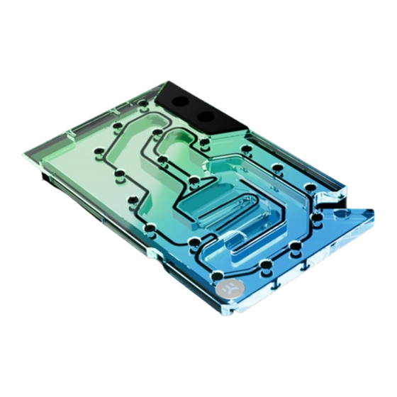
Page 6: Technical Specifications And Water Block Parts
TECHNICAL SPECIFICATIONS AND WATER BLOCK PARTS NICKEL PLEXI Technical Specification: Dimensions (L x H x W): 214 x 128 x 33,5 mm D-RGB cable length: 500 mm D-RGB LED count: 11 D-RGB connector standard 3-pin (+5V, Data, Blocked, Ground Position Description Quantity 107964... -
Page 7: Preparing The Graphic Card
PREPARING THE GRAPHIC CARD REMOVING THE STOCK COOLER NVIDIA FE GEFORCE RTX 5090 Important! Before starting, make sure to have a clean, flat surface to work on. It is recommended to put foam or soft material to lay the graphics card on. STEP 1 First, remove two (2) screws from the back of the stock cooler (with a Torx head screwdriver). - Page 8 STEP 3 Unscrew four (4) screws holding triangle-shaped covers. Slide the triangle-shaped covers by moving them around until you find the correct direction. It should slide smoothly, there is no need to apply a lot of force. STEP 3 STEP 4 PCIe PCB METAL BRACKET Unscrew six (6) screws and remove the PCIe PCB and metal bracket.
- Page 9 STEP 5 Unscrew four (4) screws and remove the backplate BACKPLATE STEP 5 STEP 6 I/O PORTS CLIP Carefuly unclip cable clips. To unclip the I/O cable, pry it using a plastic prying tool. CABLE CLIPS STEP 6 - 9 -...
- Page 10 STEP 7 Remove the retention bracket by unscrewing four (4) screws. Carefuly lift the GPU PCB STEP 7 STEP 8 Liquid metal removal PROTECTD PCB Before removing liquid metal, protect the GPU die surrounding components with painter's tape. This will ensure that the liquid metal does not come into contact with any PCB components, as it is electrically conductive.
- Page 11 STEP 9 To remove the fans, unscrew the eight (8) screws located between the fan blades. STEP 9 STEP 10 BACK FRONT To detach the cooler from its housing, carefully bend back four metal spring clips: three in the front and one in the back. Lift the cooler while bending back one clip at a time.
-
Page 12: Preparing The Water Block For Installation
STEP 11 I/O CABLE Carefully remove the I/O cable assembly from the housing. The cable is glued to the side of the housing. Use a thin plastic prying tool to help separate the cable from the housing. It is recommended to heat the housing for easier removal. Important! Do not use excessive force. -
Page 13: Cutting And Placing Thermal Pads - Water Block
CUTTING AND PLACING THERMAL PADS - WATER BLOCK STEP 1 Thermal Pad - VRAM - 27x16x2 The GPU water block comes with pre-cut thermal pads, but some Thermal Pad - Inductor 120x12x1 27 mm of them need to be additionally cut into smaller pieces. 120 mm Remove the protective foil from both sides of the 1 mm... - Page 14 STEP 3 72x6x2 mm Use one (1) Thermal Pad - VRAM - 27x16x2 mm Cut it in half (13,5x16 mm) Thermal Pad - VRAM - 27x16x2 27 mm 6x6x2 mm 1 mm Use Thermal Pads - VRM - 120x6x2 mm Cut one (1) to a length of 72 mm.
-
Page 15: Applying Thermal Compound
APPLYING THERMAL COMPOUND STEP 1 Apply the enclosed thermal grease (thermal compound) on the GPU die – as shown in the image. The layer of the thermal compound must be thin and even over the entire die surface. The excessive or uneven application of thermal grease may lead to poor performance! For this step, you will need: Thermal Grease... -
Page 16: Cutting And Placing The Thermal Pads - Pcb
STEP 2 CUTTING AND PLACING THE THERMAL PADS - PCB Use Thermal Pad - VRAM - 27x16x2 mm Cut nine (9) to a length of 5 mm. 5x6x2 mm Thermal Pad - VRM - 120x6x2 120 mm 2 mm STEP 2 - 16 -... - Page 17 STEP 2 Carefully position the LED PCB on the Pressure Plate. Secure it with two (2) original screws. LED PCB ORIGINAL SCREWS STEP 2 STEP 3 Attach I/O bracket to a I/O ports by screwing the original eight (8) STICKER - FLAT CABLE Torx screws.
- Page 18 STEP 4 M2.5 x 6 AX1 SCREW 1. To secure the PCB to the water block, use four (4) PVC washers PRESSURE PLATE and four (4) M2.5 x 4 AX1 screws. 2. Position the pressure plate and secure it by tightening four (4) M3x6 SCREW M2.5 x 6 AX1 screws..
-
Page 19: Cutting And Placing The Thermal Pads - Pressure Plate
STEP 5 ORIGINAL SCREWS Connect PCIe PCB to a GPU PCB and secure it with five (5) original Torx screws, along with a metal plate. METAL PLATE PCIe PCB STEP 5 STEP 6 CUTTING AND PLACING THE THERMAL PADS - PRESSURE PLATE Use one (1) Thermal Pad - VRAM - 55x16x2 Thermal Pad - VRAM - 55x16x2... -
Page 20: Attaching The Backplate
ATTACHING THE BACKPLATE STEP 1 Position the Backplate (including screws and standoffs) onto the M2.5 x 4 AX1 SCREW GPU PCB. Use additional two(2) M2.5x4 AX1 Screws. Make sure all the holes are aligned. Tighten the screws evenly. Do not use excessive force! For this step, you will need: Phillips Head Screwdriver... -
Page 21: Connecting The D-Rgb Led Strip
STEP 5 Screw in two (2) G1/4 threaded male fittings. Attach the liquid cooling tubes and connect the water block to the cooling loop. EK- PLUG G1/4 Do not forget to plug the remaining two openings using the enclosed EK-Plug G1/4 or its equivalent. EK recommends using EK fittings with all EK water blocks. -
Page 22: Testing The Loop
Removing the label will void the leak- free guarantee, but not the guarantee on the product itself. Any other RMA issues can be reported to EK Customer Support at www.ekwb. com/support for further analysis. - 22 -... -
Page 23: Support And Service
SUPPORT AND SERVICE In case you need assistance or wish to order spare parts or a new mounting mechanism, please contact: https://www.ekwb.com/customer-suppor t/ For spare parts orders, refer to the page with “TECHNICAL SPECIFICATIONS AND WATER BLOCK PARTS” where you can find the EAN number of each part you might need.
Need help?
Do you have a question about the EK-Quantum Vector3 FE RTX 5090 and is the answer not in the manual?
Questions and answers