Table of Contents
Advertisement
Quick Links
Advertisement
Table of Contents

Related Manuals for ekwb Velocity-AMD


Summary of Contents for ekwb Velocity-AMD
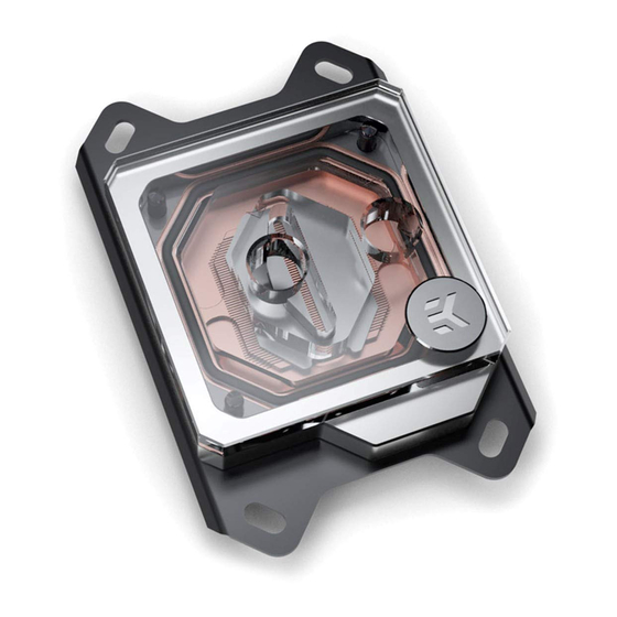
- Page 1 Velocity - AMD CPU WATER BLOCK USER GUIDE 2nd Revision, October 19th 2018...
- Page 2 The following instructions are subject to change without notice. Please visit our web site at www.ekwb.com for updates. Before installation of this product please read important notice, disclosure and warranty conditions printed on the back of the box.
-
Page 3: Table Of Contents
TABLE OF CONTENT GENERAL INFORMATION ON WATER BLOCK COMPATIBILITY SUPPORT AND SERVICE WHAT IS ENCLOSED SOCIAL MEDIA QUICK INSTALLATION GUIDE INSTALLING THE WATER BLOCK AMX AND FMX SOCKET MOTHERBOARDS CONNECTING THE RGB LED STRIP (option) CONNECTING THE RGB LED STRIP CONNECTING THE D-RGB LED STRIP - 3 -... -
Page 4: General Information On Water Block Compatibility
- PreciseMount universal CPU mounting mechanism: • Jet J2 (0.8mm* thick) • M3 threaded thumb screws (4 pcs) - Thermal Grizzly Hydronaut (EKWB 1.0g) thermal grease • LGA-2011 M3 threaded mounting studs (4 pcs) • Springs (4 pcs) • M3 threaded thumb nuts (4 pcs) •... -
Page 5: Installing The Water Block
INSTALLING THE WATER BLOCK AMx AND FMx SOCKET MOTHERBOARDS STEP 1 UNC 6-32 AMD® factory backplate Removing of the original plastic hold-down clamps and the Screws factory backplate: Using Philips-head screwdriver remove the four UNC 6-32 screws securing the original plastic hold-down clamps around the socket as shown on the sketch. - Page 6 STEP 3 Install backplate rubber gasket and place metal backplate for AMD® socket to the back of your motherboard RIBBED SIDE UP! (facing Metal away from the motherboard) Align the holes on the motherboard Backplate with holes on rubber gasket and backplate. Carefully rotate motherboard assembly with front side facing up with one hand while holding the backplate and rubber in place with the other hand.
- Page 7 STEP 5 leaning the CPU: Wipe the CPU’s contact surface (by using non– abrasive cloth or Q-tip, as shown on sample photo). Non-abrasive Applying thermal compound: On a clean IHS, apply a line of cloth thermal compound and spread it over the whole CPU heat spreader (IHS) with a credit card or equivalent - see sample photo on left.
- Page 8 STEP 7 Fitting Ring Tighten the fitting barbs in clockwise direction until the gasket underneath is compressed. The installation of the CPU water block is now complete. Fitting Barb Inlet port Outlet port Before proceeding with the installation It is mandatory to remove the protective foil from the backside of the water block.
-
Page 9: Connecting The Rgb Led Strip (Option)
CONNECTING THE RGB LED STRIP (option) CONNECTING THE RGB LED STRIP STEP 1 Plug the 4-pin connector from Water block’s and Fan’s RGB LED light to the RGB HEADER on the motherboard. The LED will work if the pin layout on the header is as follows: +12V G R B. Please ensure that the arrow indicated on the connector is plugged into the +12V line as indicated on your motherboard. -
Page 10: Connecting The D-Rgb Led Strip
CONNECTING THE D-RGB LED STRIP STEP 1 Plug the 4-pin connector from Water block’s D-RGB LED light to the DRGB HEADER on the motherboard. The LED will work if the pin layout on the header is as follows: +5V, Digital, empty, Ground. Please ensure that the arrow indicated on the connector is D-RGB Header plugged into the +5V line as indicated on your motherboard. -
Page 11: Support And Service
SUPPORT AND SERVICE For assistance please contact: http://support.ekwb.com/ EKWB d.o.o. Pod lipami 18 1218 Komenda Slovenia - EU SOCIAL MEDIA EKWaterBlocks @EKWaterBlocks ekwaterblocks EKWBofficial ekwaterblocks...
Need help?
Do you have a question about the Velocity-AMD and is the answer not in the manual?
Questions and answers