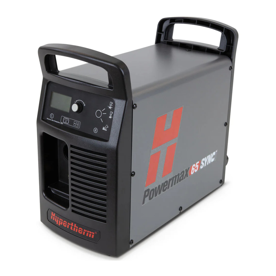
Hypertherm Powermax 65 / 85 / 105 / 125 / 65 SYNC / 85 SYNC / 105 SYNC Manual
Also See for Powermax 65:
- Service manual (248 pages) ,
- Operator's manual (156 pages) ,
- Field service bulletin (16 pages)
Advertisement
Table of Contents
Contents
Hypertherm Powermax 65 / 85 / 105 / 125 / 65 SYNC / 85 SYNC / 105 SYNC Manual
Introduction
Purpose
This Field Service Bulletin describes the steps for locking the Powermax65/85/105/125 power supply onto the wheel kit (wheel cart).
Materials and tools
No special tools are required.
Kit 229370 contents
| Part number | Description | Quantity |
| 229370 | Kit: Powermax65/85 wheel kit (fully assembled) and Powermax65/85 SYNC | 1 |
Kit 229467 contents
| Part number | Description | Quantity |
| 229467 | Kit: Powermax105/125 wheel kit (fully assembled) and Powermax105 SYNC | 1 |
Locking the power supply to the wheel cart


- Lift the locking pin (1) straight up. The pin is connected to the axle with a wire cable.
- Push the rear locking mechanism handle (2) forward toward the casters (3) and slide the locking mechanism until the mechanism stops.
- Place the power supply (4) onto the wheel cart so that the front feet of the power supply are over the casters (3). Center the power supply on the rails. Wheel kit 229467 has two positioning labels on the wheel kit frame. (See the figures on the previous page.) The starting line on the label should be flush with, or just covered by, the corner on the front panel of the power supply.
- Hold the cart and pull the rear locking mechanism handle (2) toward the rear of the cart until the mechanism stops.
The locking mechanism pulls the power supply to the rear of the cart until the front and rear feet of the power supply engage the front and rear tabs of the locking mechanism. - Insert the locking pin (1) through the rear locking mechanism handle (2) and into the wheel cart frame until the pin is fully seated in the frame.
- Carefully lift the power supply handles (5) to verify that the power supply is securely attached to the front and rear of the cart. If the power supply is not secured to the cart, repeat the procedure.
The power supply is locked into place. You can position the Powermax by lifting the front handle and rolling the system on the rear wheels of the cart. - Press the brake pedal (6) down on both casters to prevent the power supply from rolling.


Removing the power supply from the wheel cart

- Lift the locking pin (1) straight up.
- While holding the cart, push the power supply (4) toward the front of the cart until the power supply stops.
- Push the rear locking mechanism handle (2) forward toward the casters (3) until the mechanism stops. The front and rear feet of the power supply are disengaged from the front and rear tabs of the locking mechanism.
- Carefully lift the power supply handles (5) to remove the power supply from the cart.
- Pull the rear locking mechanism handle to the rear of the cart and replace the locking pin.
 |  |  ELECTRIC SHOCK CAN KILL |
 | Disconnect electrical power before performing any maintenance. See the Safety and Compliance Manual included with your system for more safety precautions. | |

Documents / ResourcesDownload manual
Here you can download full pdf version of manual, it may contain additional safety instructions, warranty information, FCC rules, etc.
Download Hypertherm Powermax 65 / 85 / 105 / 125 / 65 SYNC / 85 SYNC / 105 SYNC Manual
Advertisement


Need help?
Do you have a question about the Powermax 65 and is the answer not in the manual?
Questions and answers