
Related Manuals for Hypertherm PowerMax 1000


Summary of Contents for Hypertherm PowerMax 1000
- Page 1 CNC Plasma Cutter Training Basics for using the PlasmaCAM Table and Hypertherm powermax 1000 CNC Plasma Cutter...
- Page 2 Agenda Safety First The Equipment -- PlasmaCAM Table The PlasmaCAM Software The Equipment -- Hypertherm Powermax 1000 Bringing it all together Other information...
-
Page 3: Safety First
Safety First!!! You are responsible for your safety and the safety of the people around you. This equipment may interfere with pacemakers/hearing aids Use the machine at your own risk... - Page 4 Safety First!!! DO NOT: Put hands on the gantry rails. You will lose fingers! Cut these materials due to TOXIC fumes : Anything cleaned with chlorinated cleaner (e.g. brake cleaner) –PHOSGENE gas is generated Galvanized steel – causes “galvanize poisoning” ...
- Page 5 Safety First!!! Read/review the Operators manual for the Hypertherm 1000 and the new torch (Duramax retrofit) (https://dallasmakerspace.org/wiki/CNC_Plasma_Cutter_Training# Equipment) Proper attire Closed toe shoes Natural fiber garments instead of synthetics Wear proper PPE AWS recommends shade 8 or greater eyewear ...
- Page 6 The Equipment – Overview Exhaust fan Switch Hypertherm Powermax 1000 power supply PlasmaCAM computer PlasmaCAM table...
- Page 7 The Equipment – PlasmaCAM Table Control Panel Torch carrier Gantry No Hands Along the Yellow Paths!
- Page 8 The Equipment – Control Panel Power Switch Emergency STOP button Cutting Switch Z-axis jog X-Y axis jog Note: the software MUST be launched and operating before this control panel will work. (See next section)
- Page 9 The Equipment – Control Panel (Ready) Power is on Cutting is on auto Z-axis is selected Z-axis jog for large movements Axis shuttle for minor movements (usually used for Z-axis in this class) X-Y movement can be done here, but is better done in the software.
- Page 10 The Equipment – Table Torch Carriage Detail Carriage Torch Torch holder clamp screw Torch handle holder clamp screw Business end of torch...
- Page 11 The Equipment – Table Stanchion Detail These points, which hold the stock, are called “stanchions” and are indicated in the software as blue dots. They are to be avoided when cutting.
- Page 12 The Equipment – Placing Stock on the Table All this work CAN be done without stock loaded in the bed, but it seems like a better choice to load the material first, and then walk through these steps to make sure the cuts will happen as desired on the actual material If needed, perform an “Initialize”...
- Page 13 The PlasmaCAM Software – Steps to Cut Position the stock and torch as needed to clear stanchions, previous cuts, or other obstacles Import or draw the design (we will focus on import) Create the cut paths Link design lines which might not be constrained from the drawing ...
- Page 14 The PlasmaCAM Software – Getting Started Launch the software (PlasmaCAM) from the desktop shortcut, or from the start menu Accept the Windows UAC message to continue Initialize the torch/software using Machine->Initialize This sends the torch carrier to the top, left, and raises the Z axis full up ...
- Page 15 The PlasmaCAM Software -- Launching These dots indicate the support stanchions These lines indicate the border of the bed...
- Page 16 The PlasmaCAM Software -- Stanchions The finger shows the real; the arrow shows the software representation...
- Page 17 The PlasmaCAM Software -- Importing Import the file containing your design Browse along the path to the saved file. Here are some of the file types supported by PlasmaCAM (some restrictions apply, e.g. BMP can only be 256 colors or less)
- Page 18 The PlasmaCAM Software –Imported Design Notice the entire design is green. This is how the design looks when it is “selected”. You can try to move the design at this point, but it is likely you will need to link the segments (next section) for a successful move.
- Page 19 The PlasmaCAM Software – Linking Segments Before the image can be moved, we must ensure the cut paths are linked These purple cut lines will be a full, uninterrupted cut (they are linked or constrained) These white cut lines are not linked (they are NOT constrained) In this example, we DO want the...
- Page 20 The PlasmaCAM Software – Linking Segments White segments appear if the cut lines are not linked. To select the parts to link: click, hold, and drag the selection box to fully surround the parts to link OR hold CTRL key while clicking the links to be added Once all parts are selected, use Edit->Link Segments (or press “K”) to ...
- Page 21 The PlasmaCAM Software – Linking Segments Auto Linking of path segments can be modified here. This may make the lines link properly if the current settings are not working. Gap distance to jump can be lowered or raised to achieve the desired affect.
- Page 22 The PlasmaCAM Software – Linking Segments Now that the lines have been linked, all of the cut lines show purple, are constrained or linked, and will be cut in a single motion per line shape.
- Page 23 The PlasmaCAM Software – Imported File Remember we wanted to move the design to avoid cut paths on the support stanchions Now we can select the whole image (click and drag a window), as indicated by the green line color Moving is up next...
- Page 24 The PlasmaCAM Software -- Moving With the parts selected (green in color) go to Edit->Move (or press “M”) to enter “move mode”. Notice the cross-hairs cursor. Then click (and release) the mouse button to create an index point anywhere on the image (choose carefully and it will make the move easier to see);...
- Page 25 The PlasmaCAM Software -- Moving Note some of these cuts are a little close for thicker materials. Thinner materials can tolerate closer cut lines. Portions can be moved by clicking on them while holding CTRL. Then move by Edit->Move to (or press “M”);...
- Page 26 The PlasmaCAM Software – Snapping Snapping can be turned on in Machine->Settings->Drawing View. Sometimes this makes arrangement easier. Alternately, sometimes it makes it more difficult, so try it either way if getting a preferred position is proving problematic.
- Page 27 The PlasmaCAM Software – Creating Cut Paths Starting the cut is important, and this is part of creating cut paths To achieve a smooth/uninterrupted cut, start in the scrap portion of the stock To create a hole, for example, click on the inside of the hole in the drawing ...
- Page 28 The PlasmaCAM Software – Creating Cut Paths To create the cut path: Open Machine->Convert to Cut Path (or press “P”) Select the starting point Right click (or press ESC) Note the outline is now blue to indicate the cut path has been set...
- Page 29 The PlasmaCAM Software –Cutting Order Now that we have our segments linked as desired, and have the path the torch will take to cut the design, we have to tell it what order to cut the parts. Cut smaller parts first ...
- Page 30 The PlasmaCAM Software –Cutting Order Open Machine->Reorder Path(s) ->Pick Order...
- Page 31 The PlasmaCAM Software –Cutting Order The mouse will be cross-hairs Select the segments in order Once selected the segments become red Once completed right click (or press ESC) NOTE: there is no indication of the order selected. You must remember. If you think you want to change it, you have to re-do the whole selection.
- Page 32 That is the order which will be used. Doing a “dry run” by leaving the PlasmaCAM table “cutting” setting OFF is recommended. Then repeat the process with it on to actually make the cuts. Next: The Equipment – Hypertherm PowerMax 1000...
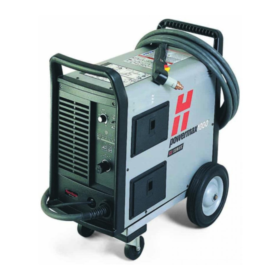
- Page 33 The Equipment – Hypertherm powermax 1000...
- Page 34 The Equipment – Hypertherm powermax 1000 On the BACK Power switch Gas (Air) hose inlet Gas (Air) dryer/filter Power cord...
- Page 35 The Equipment – Hypertherm powermax 1000 On the front Current (amps) adjustment knob Mode switch Status Indicators Gas (air) pressure gauge Gas (air) pressure regulator adjustment knob...
- Page 36 The Equipment – Hypertherm powermax 1000 Yellow Too Low Too High Desired Cut may be started with air pressure too high, but for best quality should be adjusted down, keeping an eye on the indicator to avoid dropping too low. Note: Indicator usually shows “high” when first...
- Page 37 Bringing it all Together – Check Consumables Bring the torch front and center so it can be removed and checked over Note the yellow crosshairs on the monitor mark the torch location To move the torch: Machine->Move To (OR press V) ...
- Page 38 The Equipment – Hypertherm powermax 1000 General Guidelines -- Torch Condition Check the torch head Are they the right parts? Use the right consumables (next section) for the stock thickness Are they in good working order? ...
- Page 39 The Equipment – Hypertherm powermax 1000 Here are pictures of consumables: notice the markings in very small print/etching...
- Page 40 The Equipment – Hypertherm powermax 1000 Buying Consumables DMS makes an effort to have good equipment on hand, but for best results, plan to supply your own Local walk-up source, if you’re in a hurry, is Metroplex Welding supply ...
- Page 41 The Equipment – Hypertherm powermax 1000 General Guidelines Rated duty cycle is 40%. PLEASE do not abuse this. Translates to 4 minutes of actual cutting for every 10 of “use” Time a “dry run” to see how long your design will take to cut ...
- Page 42 The Equipment – Hypertherm powermax 1000 It is imperative that the work piece is grounded. If it is not grounded it can ruin the torch, and possibly the entire CNC system...
- Page 43 The Equipment – Hypertherm powermax 1000 This is what can happen if grounding is not properly done. The arc found a ground other than the intended path (tip of the electrode, through the work piece) and melted the side off the torch arcing to the carrier.
- Page 44 The Equipment – Hypertherm powermax 1000 Selecting Amps, cut speeds, etc. The black book kept with the Hypertherm power supply will be an appropriate starting point. However, you should consult the wiki (https://dallasmakerspace.org/wiki/CNC_Plasma_Cutter_Training#Equip ment) for more up-to-date information about the DuraMAX torch.
- Page 45 The LED will be green in the Auto portion of the control panel Front panel of the Hypertherm power supply for fault indications Yellow Torch LED -- Check the torch head cup for tightness Yellow Temp LED -- power supply is too hot ...
- Page 46 Bringing it all Together – Load & Initialize If not already done, turn on the PlasmaCAM table If not already done, turn on the PC and launch the PlasmaCAM software Initialize the PlasmaCAM software (re-do this after ANY settings changes, or “just to be sure”) ...
- Page 47 Bringing it all Together – Power Up Turn the Exhaust fan on Doing this before the air hose is attached allows you to hear the fan spool up. This takes about 60 seconds Do torch checks ...
- Page 48 Bringing it all Together – Adjust Torch & Stock Manually adjust the Z axis to about 1/16(0.0625)”- 1/8(0.1250)” above the stock Use a penny (0.0598”) to gauge (– it should just drag when sliding between the stock & the torch tip ...
- Page 49 Other Information –Speed Machine->Settings holds the settings for the PlasmaCAM. This is the first screen that comes up and is for the speeds. The cutting portion is where we really need to pay attention. **After changing any of the settings be sure to initialize the machine...
- Page 50 Other Information – Path Conversion Arc Conversion configures how line segments are smoothed into arcs Torch lead in is configured here. Small cuts need smaller lead in. Standard cuts need larger lead in for better finish quality Offset configures the offset of the kerf...
- Page 51 Other Information – Height Control Auto torch height is not currently used. In the near future we hope to have it working. It will allow better control for thinner materials and help reduce warping.
- Page 52 Make sure that it is a good speed and realize other items that may need to be set up when these are adjusted. The black book kept with the Hypertherm power supply will be an appropriate starting point. However, you should consult the wiki (https://dallasmakerspace.org/wiki/...
- Page 53 Other Information – Reference Cuts If stock needs to be repositioned after a cut has been made, for example, to avoid stanchions, make reference cuts in the stock which are the diameter of the shield Use the PlasmaCAM software to draw a circle or two for reference before making any other cuts ...
- Page 54 Other Information – Reference Cuts 2 reference holes: Use these points to If stock shifts during a cut maneuver the stock create a “break” where the back into position cut ended by with Edit- >Break (OR press “B”), then select the point & click Re- initiating the cut will Notice the...
- Page 55 Summary Turn the computer on, log on, launch PlasmaCAM software Turn the Exhaust fan on Turn the PlasmaCAM table on Initialize the PlasmaCAM table in the software Bring the torch front and center, check for proper assembly/within operating specifications ...
Need help?
Do you have a question about the PowerMax 1000 and is the answer not in the manual?
Questions and answers