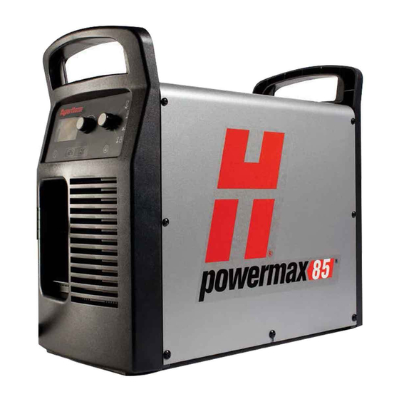
Hypertherm Powermax 65 Field Service Bulletin
Digital signal processor (dsp) board replacement
Hide thumbs
Also See for Powermax 65:
- User manual ,
- Service manual (248 pages) ,
- Operator's manual (156 pages)
Table of Contents
Advertisement
Available languages
Available languages
Advertisement
Table of Contents

Summary of Contents for Hypertherm Powermax 65
- Page 1 Powermax65/85/105 Digital Signal Processor (DSP) Board Replacement Remplacement du circuit imprimé du processeur de signal numérique (DSP) du Powermax65/85/105 Field Service Bulletin Bulletin de service sur le terrain 806700 – Revision 2 – June 2013 Révision 2 — Juin 2013...
-
Page 3: Materials And Tools
This Field Service Bulletin describes the procedure for replacing the digital signal processor (DSP) board in the power supply. Powermax105 systems: Complete instructions for installing this repair kit are included in the Powermax105 Service Manual. To download the Service Manual, go to www.hypertherm.com and click the “Downloads library” link. Materials and tools #2 Phillips screwdriver... -
Page 4: Remove The Power Supply Cover And Mylar Barrier
DSP boarD rePlacement Remove the power supply cover and Mylar barrier 1. Turn OFF the power, disconnect the power cord, and disconnect the gas supply. 2. Using a TORX or blade screwdriver, remove the 8 small screws (2) from the power supply cover. 3. -
Page 5: Remove The Dsp Board
DSP boarD rePlacement Remove the DSP board 1. Disconnect the DSP connector (1) from the top of the DSP board (3). Note: This step is only required on systems that have an RS485 communication board installed. Systems without an RS485 communication board installed will not have a connector plugged into the top of the DSP board. - Page 6 DSP boarD rePlacement Install the new DSP board 1. Connect the ribbon cable to the ribbon cable connector (6) on the back of the new DSP board (3). 2. Align the two alignment pins (7) with the corresponding holes on the power board. 3.
-
Page 7: Replace The Mylar Barrier
DSP boarD rePlacement Replace the Mylar barrier 1. Carefully push in the sides (1) of the Mylar barrier so that the barrier bends out slightly at the top and bottom (2). 2. Slide the sides of the Mylar barrier behind the power supply frame (3). Be careful to get the barrier between the frame and the power wires on the right side of the power board (4). -
Page 8: Replace The Power Supply Cover
DSP boarD rePlacement Replace the power supply cover 1. Place the cover (3) over the power supply. Be careful not to pinch any wires. 2. Using a TORX or blade screwdriver, install the 8 small screws (2) into the power supply cover. Tighten the screws to 15 in lbs (17.3 kg cm). - Page 9 (DSP) de la source de courant. Systèmes Powermax105 : Les instructions complètes pour l’installation de ce kit de réparation sont incluses dans le Manuel de service du Powermax105. Pour télécharger le Manuel de service, se rendre sur www.hypertherm.com et cliquer sur le lien « Bibliothèque des téléchargements ».
- Page 10 Remplacement du ciRcuit impRimé du pRocesseuR de signal numéRique Dépose du couvercle de la source de courant et de la barrière Mylar 1. Couper l’alimentation (OFF), débrancher le cordon d’alimentation et débrancher l’alimentation en gaz. 2. À l’aide d’un tournevis plat ou TORX, déposer les 8 petites vis (2) du couvercle de la source de courant. 3.
- Page 11 Remplacement du ciRcuit impRimé du pRocesseuR de signal numéRique Retrait du circuit imprimé du processeur de signal numérique 1. Débrancher le connecteur du processeur de signal numérique (1) du haut du circuit imprimé du DSP (3). Note : Cette étape n’est requise que pour les systèmes équipés d’une carte de communication RS485. Sur les systèmes qui n’en sont pas dotés, le dessus du circuit imprimé...
- Page 12 Remplacement du ciRcuit impRimé du pRocesseuR de signal numéRique Insertion du circuit imprimé neuf du processeur de signal numérique 1. Débrancher le câble plat du connecteur du câble plat (6) au dos du circuit imprimé neuf du processeur de signal numérique (3).
- Page 13 Remplacement du ciRcuit impRimé du pRocesseuR de signal numéRique Remise en place de la barrière Mylar 1. Enfoncer soigneusement les côtés (1) de la barrière Mylar de façon à ce qu’elle fléchisse légèrement à ses parties supérieure et inférieure (2). 2.
- Page 14 Remplacement du ciRcuit impRimé du pRocesseuR de signal numéRique Remise en place du couvercle de la source de courant 1. Placer le couvercle (3) sur la source de courant. S’assurer de ne pincer aucun fil. 2. À l’aide d’un tournevis plat ou TORX, insérer les 8 petites vis (2) dans le couvercle de la source de courant. Visser les vis à...
- Page 16 Tous droits réservés Hypertherm, Phoenix, and EDGE are trademarks of Hypertherm, Inc. and may be registered in the United States and/or other countries. Hypertherm, Phoenix et EDGE sont des marques d’Hypertherm, Inc. qui peuvent être déposées aux États-Unis et/ou dans d’autres pays.


Need help?
Do you have a question about the Powermax 65 and is the answer not in the manual?
Questions and answers