Table of Contents
Advertisement
Quick Links
Advertisement
Chapters
Table of Contents

Related Manuals for Hypertherm POWERMAX 800


Summary of Contents for Hypertherm POWERMAX 800
- Page 1 ® Plasma Arc Cutting System Service Manual 802280 - Revision 4 EN50199 EN50192...
- Page 2 P.O. Box 5010 Hanover, New Hampshire 03755-5010 Tel.: (603) 643-3441 Fax: (603) 643-5352 © Copyright 1997 Hypertherm, Inc. All Rights Reserved HYPERTHERM and POWERMAX are trademarks of Hypertherm, Inc. and may be registered in the United States and/or other countries...
- Page 3 Hypertherm Offices Worldwide : Hypertherm, Inc. Etna Road, P.O. Box 5010 Hanover, NH 03755 USA Tel.: (603) 643-3441 (Main Office) Fax: (603) 643-5352 (All Departments) Tel.: (800) 643-9878 (Technical Service) Tel.: (800) 737-2978 (Customer Service) Hypertherm Plasmatechnik GmbH Ohmstrasse 6 D–63477 Maintal, Germany...
- Page 4 LECTROMAGNETIC OMPATIBILITY EMC INTRODUCTION f. Equipment used for calibration or Equipotential Bonding measurement. The 400V CE power supply has been built g. Immunity of other equipment in the Bonding of all metallic components in the in compliance with standard EN50199. To environment.
-
Page 5: Patent Indemnity
Hanover, New Hampshire, all costs, insurance and freight prepaid, and which examination proves not to be free from defects in materials and workmanship. HYPERTHERM shall not be liable for any repairs, replacements, or adjustments of Products covered by this warranty, except those made pursuant to this paragraph or with HYPERTHERM's written consent. -
Page 6: Table Of Contents
ABLE OF ONTENTS SECTION 1 SAFETY ........................1-1 About Notes, Cautions & Warnings ........................1-2 Safety Instructions .............................. 1-2 Eye Protection ............................. 1-2 Skin Protection ............................. 1-2 Toxic Fume Prevention ..........................1-2 Fire Prevention ............................. 1-2 Electric Shock Prevention ..........................1-2 Explosion Prevention ........................... - Page 7 ABLE OF ONTENTS SECTION 5 PARTS LIST - CE ..................... 5-1 Power Supply - 400V CE ............................. 5-2 PAC121TS Torch Assembly ..........................5-10 PAC121MS Torch Assembly ..........................5-11 Consumable Parts - CE ............................. 5-12 Powermax800 Field Upgrade Kits and Optional Parts ..................5-13 Power Supplies - 400V CE ..........................
-
Page 8: Section 1 Safety
Be aware of anything touching the workpiece. The workpiece is part this hazard, which has potential for of the electrical circuit. serious bodily injury. HYPERTHERM Plasma Systems 10/24/96... -
Page 9: Safety
– Install protective screens or curtains to reduce ultraviolet transmission. Electric Shock Prevention All Hypertherm plasma systems use high Skin Protection voltage (up to 280 VDC) to initiate the plasma arc. Take the following precautions when • Wear protective clothing to protect against burns... -
Page 10: Explosion Prevention
(CSA) or applicable national or local codes. • Examine hoses at regular intervals for leaks, wear, loose connections or other hazard. • Never use a cylinder that leaks or is physically • Replace hose that is damaged in any way. damaged. HYPERTHERM Plasma Systems 10/24/96... -
Page 11: Grounding
• Coil any excess hose and place it out of the way to the retaining cap is loosened. prevent damage and to eliminate the danger of • Each Hypertherm plasma system is designed to be tripping. used only with specific Hypertherm torches. Do not... -
Page 12: Section 1A Sécurité
Se référer à l’annexe du manuel pour plus de • Ne pas couper de récipients contenant des matières renseignements sur les collecteurs d’aération. combustibles. HYPERTHERM Systèmes plasma 1a-1 10/6/98... -
Page 13: Prévention Des Chocs Électriques
• Installer un sectionneur avec fusibles appropriés, à la prise de terre appropriée. proximité de la source de courant. Ce dispositif permet à • Chaque système plasma Hypertherm est conçu pour être l’opérateur d’arrêter rapidement la source de courant en utilisé uniquement avec des torches Hypertherm cas d’urgence. -
Page 14: Mise À La Masse Et À La Terre
Bien serrer l’écrou de retenue. Table de travail Raccorder la table de travail à la terre, • S’assurer que toutes les connexions sont bien serrées conformément aux codes de sécurité locaux ou nationaux pour éviter la surchauffe. appropriés. HYPERTHERM Systèmes plasma 1a-3 4/9/99 10/6/98... - Page 15 • Faire passer le faisceau de la torche le plus près possible du câble de retour. • Ne pas s’enrouler le faisceau de la torche ou le câble de retour autour du corps. • Se tenir le plus loin possible de la source de courant. 1a-4 HYPERTHERM Systèmes plasma 10/6/98 10/16/98...
-
Page 16: Description & Specifications
& S ESCRIPTION PECIFICATIONS Section 2 DESCRIPTION & SPECIFICATIONS In this section INTRODUCTION .................. 2-2 SPECIFICATIONS................2-3 PAC121 50A Torches ................2-4 IEC SYMBOLS USED ................2-6 Service Manual 9-96... -
Page 17: Introduction
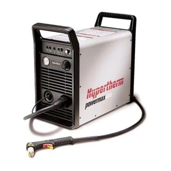
& S ESCRIPTION PECIFICATIONS INTRODUCTION The Powermax800 plasma cutting system uses an inverter power supply to provide a smooth DC output voltage producing excellent cut and gouge quality on mild steel, stainless steel, aluminum and other metals. The Powermax800 power supply provides constant-current output variable from 20 to 50 amps, for optimum performance on all thicknesses of metal up to 1/2 inch (12 mm) thick. -
Page 18: Figure 2-2 Powermax800 Power Supply With Dimensions
& S ESCRIPTION PECIFICATIONS SPECIFICATIONS Power Supply Rated Open Circuit Voltage (OCV) (U ) ....300VDC Rated Output Current (I ) ........20-50 amps Rated Output Voltage (U ) ........120VDC Duty Cycle (X) @ 40°C ........50% (I =50A, U =120V) 100% (I =44A, U... -
Page 19: Pac121 50A Torches
& S ESCRIPTION PECIFICATIONS Weight ................65 pounds (30 kg) without wheels 72 pounds (33 kg) with wheels 128 pounds (58 kg) for 600V power supply Gas Type ...............Air or Nitrogen Gas Quality, Air ............. Clean, dry, oil-free Gas Quality, Nitrogen ............ 99.995% pure Gas Inlet Pressure ............ - Page 20 & S ESCRIPTION PECIFICATIONS MARK The Powermax800 conforms to standard EN50192. The S mark indicates that the power supply and torch are suitable for use in environments with increased hazard of electrical shock. The torches must have shielded consumable parts to maintain S mark compliance. See warning below and Figure 2-5.
-
Page 21: Iec Symbols Used
& S ESCRIPTION PECIFICATIONS IEC SYMBOLS USED Direct Current (DC) Alternating current (AC) Plasma cutting torch AC input power connection The terminal for the external protective (earth) conductor An inverter-based power source Anode (+) work clamp Temperature switch Pressure switch Plasma torch in the TEST position (cooling and cutting gas exiting nozzle) Power is on Power is off... -
Page 22: Maintenance
AINTENANCE Section 3 MAINTENANCE In this section: Introduction ..................3-2 Routine Maintenance ................3-2 Bowl Draining/Filter Element Cleaning ..........3-2 Cooling Air Filter Removal, Cleaning and Replacement....3-3 Theory of Operation ................3-4 Sequence of Operation ................ 3-6 Troubleshooting..................3-7 Test Equipment ................ -
Page 23: Introduction
AINTENANCE INTRODUCTION This section provides service technicians with routine maintenance, theory of operation and troubleshooting of the power supply. Also included in this section is the sequence of operation, power board and control board test points, and the removal and replacement procedures for the PAC121T trigger torch and PAC121M machine torch parts. -
Page 24: Figure 3-2 Air Filter Removal
AINTENANCE Cooling Air Filter Removal, Cleaning and Replacement Powermax800 systems are normally shipped without air filters. If your Powermax800 has the air filter option, it will need cleaning periodically. Excessively dirty or dusty environments can block the cooling air filter (if installed) and cause the power supply to overheat and shut down. WARNING SHOCK HAZARD: Always turn off power and unplug cord from wall and wait 5... -
Page 25: Theory Of Operation
AINTENANCE THEORY OF OPERATION General The Powermax800 is a multi-voltage, multi-phase power supply. The two inverter inputs are linked in parallel for 208 or 240V on the 208/240/480V units, and for 200 or 230V on the 200/230/400V units. The inverters are linked in series for 480V on the 208/240/480V units, and for 400V on the 200/230/ 400V units. -
Page 26: Sequence Of Operation
AINTENANCE SEQUENCE OF OPERATION Shaded boxes represent operator action. Clear boxes represent results from operator action. System off • Connect gas supply to filter-regulator on power unit • Apply power at line voltage disconnect box. • Set power circuit breaker S1 to ON (1). After five seconds, LINE VOLTAGE and TEMP LEDs •... -
Page 27: Troubleshooting
The complexity of the circuits require that service technicians have a working knowledge of inverter power supply theory. In addition to being technically qualified, technicians must perform all testing with safety in mind. If questions or problems arise during servicing, call the Hypertherm Technical Services Department at 1 800 643 9878. Test Equipment •... -
Page 28: Visual Inspection - Internal
If power is required for servicing, be aware that dangerous voltages exist within the power supply which could cause serious injury or death. If questions or problems arise during servicing, call the Hypertherm Techni- cal Services department at 1-800-643-9878. WARNING The aluminum heatsink on the power PC board is electrically live when the plasma is on. -
Page 29: Initial Resistance Checks
Removal of the protective conformal coatings and other unauthorized repairs to the PC boards will void the warranty. If questions or problems arise during servicing, call the Hypertherm Tech- nical Services department at 1-800-643-9878. 1. Set the Powermax800 power switch to O (off), unplug the power cord, and disconnect the gas supply - see warnings. - Page 30 AINTENANCE Single-Phase Check # 1 Set power switch S1 to OFF (0) Measure resistance between the conductors (line and neutral) on the plug of the power cord. Do not use the ground conductor on the plug as a measuring point. Check power cord and power Meter switch S1.
- Page 31 AINTENANCE Three-Phase Check # 1 Set power switch S1 of OFF (0) Measure resistance between the conductors connected to link box terminal TB1-1 & TB1-2, TB1-1 & TB1-3, and TB1-2 & TB1-3 on the plug of the power cord. Do not use the ground pin on the plug as a measuring point.
- Page 32 AINTENANCE From From page 3-11 page 3-11 page 3-13 Indicates Check # 2 low ohms or short Isolate and check control transformer T1, power switch S1, input filter MOV1, capacitors C1, C2 and C3, contactor CR1 and all associated wiring for shorts.
- Page 33 AINTENANCE Check #2 All Power Supplies Disconnect torch lead. Place + lead of ohm meter to upper bar spanning output diodes D2 and D3. Place – lead of ohm meter to lower bar spanning output diodes D2 and D3. Meter indicates Replace diodes D2 and D3.
- Page 34 AINTENANCE Check # 3 All Power Supplies Start Measure resistance between the power supply chassis and the conductors on the plug of the power cord. Do not use the ground conductor on the plug as a measuring point. Meter indicates an open ? There is an internal short in the power supply.
- Page 35 AINTENANCE Check # 4 All Power Supplies Start Measure resistance between the power supply chassis and the work cable clamp (Fig 4-1). Meter indicates an open ? There is an internal short in the power supply. Visually and with a meter, inspect the unit for pinched, broken, and loose wires and wires with damaged insulation contacting the chassis.
- Page 36 AINTENANCE Check # 5 All Power Supplies Start Measure resistance between the conductors on the plug of the power cord and the work cable clamp. Do not use the ground conductor on the plug as a measuring point. Meter indicates an open ? There is an internal short in the power supply.
-
Page 37: Corrective Maintenance Checks
If power is required for servicing, be aware that dangerous voltages exist within the power supply which could cause serious injury or death. If questions or problems arise during servicing, call the Hypertherm Techni- cal Services department at 1-800-643-9878. WARNING The aluminum heatsink on the power PC board is electrically live when the plasma is on. - Page 38 Note: The corrective maintenance flow charts are "best-guess" solutions. Study the system wiring diagram and understand the theory of operation before troubleshooting. Before purchasing a major replacement component, check with Hypertherm's Technical Service group at 1 800 643 9878 or the nearest Hypertherm repair facility.
- Page 39 AINTENANCE Start Correct voltage links. See Set power switch S1 to ON (1) label in linkbox and Powermax800 Operator Manual (IM227) Section 3. Note: 400V CE power supplies page 3-20 S1 shuts OFF have no link box Power supply LINE VOLTAGE LED linked for proper lights briefly line voltage?
- Page 40 AINTENANCE From Unplug power cord. Measure resistance page 3-19 of fan M1 Resistance 208/240/480V units- approx. 190 ohms correct ? 200/230/400V units- approx. 130 ohms Check connectors & wires between fan and control board Replace M1 connector JP2 pins 12 &...
- Page 41 AINTENANCE From page 3-20 LINE VOLTAGE page 3-22 Off? Check for low input voltage at TB1 Is line voltage for: 200V < 170V? 208V < 178V? 230V < 195V? Correct supply voltage 240V < 204V? 400V < 340V? 480V < 408V? 600V <...
- Page 42 AINTENANCE From page 3-21 page 3-23 GAS PRESSURE LED On ? Check pressure regulator gauge for 70 psi Adjust pressure Pressure 70 psi? regulator for 70 psi corrected? Check inlet gas supply pressure Disconnect wires W92 & W93 on to pressure regulator. It should pressure switch PS1.
- Page 43 AINTENANCE From page 3-22 page 3-24 TEMP LED Off ? Replace temperature switch TS1. If TS1 opens again after replacement, replace heat sink SA. Unplug power cord. Allow power supply to cool down to room temperature. Plug in power cord and turn power supply on.
- Page 44 AINTENANCE From page 3-23 Press & hold GAS TEST switch S2. Adjust pressure regulator for 70 psi (4.8 bar) indication (dynamic) on gauge. Check JP4 sockets and control board pins 5 & 6. Check wires 70 psi (4.8 bar) W65 & W66. Check gas Indicates 0 psi dynamic ? solenoid V1 &...
- Page 45 AINTENANCE From page 3-24 Connect work clamp to workpiece. Set AMPS control P1 to minimum (20 amps). Depress torch start switch to transfer arc to workpiece. Check TP1 of Arc transfers control board for 12V. Replace control 12V? board Check that work clamp is making good metal-to-metal contact.
-
Page 46: Power Board
Wait at least 5 minutes after turning the power supply off before handling the PC board or capacitors. If questions or problems arise during servicing, call Hypertherm Technical Services at 1-800-643-9878. Use extreme caution when taking the voltage readings on the back of the power PCB - see warning above. -
Page 47: Figure 3-5 Back Side Of Power Board - Test Points
Removal of the protective conformal coatings and other unauthorized repairs to the PC boards will void the warranty. If questions or problems arise during servicing, call the Hypertherm Technical Services department at 1-800-643-9878. E14 - YEL... -
Page 48: Control Board
AINTENANCE CONTROL BOARD Control Board LEDs There are 4 control board LEDs visible from the Powermax800 front panel. There are 6 more LEDs that are visible only when the cover is removed. See Figure 3-6 for location of LEDs. • D8 POWER ON: Illuminates when power is applied. -
Page 49: Figure 3-6 Control Board Test Points
AINTENANCE Control Board Test Points Test Point Description Value Transfer signal. A logic high (12V) indicates that the arc is transferred. Start signal. A logic high (12V) indicates that the torch start switch is on. +12V Unregulated DC voltage. Approximately 30VDC at nominal input voltage. +18V INV-ON signal. -
Page 50: Torch Check
AINTENANCE TORCH CHECK A failure of the torch cap sensor circuit will cause the Powermax800 power supply to shut down, and a failure of the torch start circuit will prevent the torch from firing. If your Powermax800 has either of these problems and you have followed the Corrective Maintenance Checks beginning on page 3-17, proceed with the following checks. -
Page 51: Start Circuit Check
AINTENANCE TORCH CHECK (cont.) Start Circuit Check If the torch start trigger is pressed and there is no pilot arc, there could be a problem with the torch start circuit. WARNING Set the Powermax800 power switch to O (off), unplug the power cable, and disconnect the gas supply. -
Page 52: Pac121Ts Torch Parts Removal And Replacement
AINTENANCE PAC121TS TORCH PARTS REMOVAL AND REPLACEMENT Torch Main Body Removal and Replacement To remove and replace the torch main body, order the torch main body with cap-on sensor switch and refer to the following procedure and Figures 3-7 and 3-8. Set the Powermax800 power switch to O (off), unplug the power cable, and disconnect the gas supply. -
Page 53: Figure 3-8 Pac121Ts Torch Switch Removal
AINTENANCE Torch Switch Removal and Replacement To remove and replace the torch switch, order the torch switch and two splices (074069) and refer to the following procedure and Figure 3-8. See page 4-10 for a complete torch parts list. 1. Ensure the Powermax800 power switch is set to O (off), unplug the power cable, and disconnect the gas supply. -
Page 54: Pac121Ms Torch Parts Removal And Replacement
AINTENANCE PAC121MS TORCH PARTS REMOVAL AND REPLACEMENT Repair of the PAC121MS machine torch normally requires replacement of the torch main body and/or the torch lead. Order the torch main body with switch. Refer to Figure 3-9 and perform the steps below. -
Page 55: Figure 3-9 Pac121Ms Torch Assembly
AINTENANCE Cap Sensor Torch Microswitch Main Body Wires (2) Screw Blue White Torch Position Shield O-Ring Screw (3) Wires (2) Wires (2) Sleeve Torch Lead Black Plunger Torch White Wires Retaining Wires (2) Sleeve (4 ea.) Figure 3-9 PAC121MS Torch Assembly 5. -
Page 56: Quick Disconnect O-Ring Removal And Replacement
AINTENANCE QUICK DISCONNECT O-RING REMOVAL AND REPLACEMENT The quick disconnect O-ring on the PAC121 torch leads provides a tight seal between the quick disconnect plug and the power supply receptacle. This O-ring prevents plasma gas from leaking during cutting. To remove and replace the O-ring in the event of damage or wear, proceed as follows and refer to Figure 3-10. -
Page 57: Parts List
ARTS Section 4 PARTS LIST In this section: Power Supply - 208/240/480V 200/230/400V ............4-2 Front ....................4-2 Top and Right Side ................. 4-4 Bottom and Left Side ..............4-6 Rear ....................4-8 PAC121TS Torch Assembly .............. 4-10 PAC121MS Torch Assembly.............. 4-11 Consumable Parts ................ -
Page 58: Power Supply - 208/240/480V
ARTS POWER SUPPLY - 208/240/480V Note: See Section 5 Parts List 400V CE for parts and 200/230/400V components of the 400V CE Powermax800 system. Front Index No. Part No. Description Ref. Desig. Quantity 001502 Pnl:PMX800 Pwr Unit Plastic Front 001522 Chassis:PMX800 Pwr Unit 004675 Spacer:PMX800 Pressure Gauge... -
Page 59: Figure 4-1 Powermax800 - Front
ARTS POWER SUPPLY - 208/240/480V 200/230/400V Figure 4-1 Powermax800 - Front Service Manual 7-97... -
Page 60: Top And Right Side
ARTS POWER SUPPLY - 208/240/480V Note: See Section 5 Parts List 400V CE for parts and 200/230/400V components of the 400V CE Powermax800 system. Top and Right Side Index No. Part No. Description Ref. Desig. Quantity 001521 Pnl:Powermax800 Pwr Unit Center 003078 Relay:30A NO Mag Blwt QDisc Term 029674... -
Page 61: Figure 4-2 Powermax800 - Top And Right Side
ARTS POWER SUPPLY - 208/240/480V 200/230/400V Figure 4-2 Powermax800 - Top and Right Side Service Manual 9-96... -
Page 62: Bottom And Left Side
ARTS POWER SUPPLY - 208/240/480V Note: See Section 5 Parts List 400V CE for parts and 200/230/400V components of the 400V CE Powermax800 system. Bottom and Left Side Index No. Part No. Description Ref. Desig. Quantity 001521 Panel:Powermax800 Pwr Unit Center 001522 Chassis:Powermax800 Pwr Unit 004667... -
Page 63: Figure 4-3 Powermax800 - Bottom And Left Side
ARTS POWER SUPPLY - 208/240/480V 200/230/400V Figure 4-3 Powermax800 - Bottom and Left Side Service Manual 9-96... -
Page 64: Rear
ARTS POWER SUPPLY - 208/240/480V Note: See Section 5 Parts List 400V CE for parts and 200/230/400V components of the 400V CE Powermax800 system. Rear Index No. Part No. Description Ref. Desig. Quantity 001503 Pnl:Powermax800 Pwr Unit Plastic Rear 001522 Chassis:Powermax800 Pwr Unit 129068 Circuit Breaker SA:4Pole 480V W/TC... -
Page 65: Figure 4-4 Powermax800 - Rear
ARTS POWER SUPPLY - 208/240/480V 200/230/400V 10***** ***** 200/230/400V Three-phase power cord not shown in Figure 4-4 Figure 4-4 Powermax800 - Rear Service Manual 9-96... -
Page 66: Pac121Ts Torch Assembly
ARTS PAC121TS Torch Assembly and 25' (7.6 m) Lead - 083003 PAC121TS Torch Assembly and 50' (15.2 m) Lead - 083004 Part Number Description 001288 ........Handle, PAC121T 002244 ........Safety Trigger, PAC121T 005094 ........Switch, Torch Pushbutton 020351 ........Electrode, Air 020361 ........ -
Page 67: Pac121Ms Torch Assembly
ARTS PAC121MS Torch Assembly and 14 ft (4.3 m) Lead - 083049 w/pigtail, 083054 no pigtail PAC121MS Torch Assembly and 25 ft (7.6 m) Lead - 083011 w/pigtail, 083056 no pigtail PAC121MS Torch Assembly and 35 ft (10.6 m) Lead - 083044 w/pigtail, 083057 no pigtail PAC121MS Torch Assembly and 50 ft (15.2 m) Lead - 083012 w/pigtail, 083058 no pigtail Part Number Description... -
Page 68: Consumable Parts
ARTS CONSUMABLE PARTS Note: See Section 5 Parts List 400V CE for parts and Shields components of the 400V CE 120601 Powermax800 system. Retaining Cap 120301 Nozzles 120282 Shielded 120602 Figure 4-7 Consumable Parts 120438 Deflector 120301 120303 Swirl Electrodes Ring PAC121 Nonshielded... -
Page 69: Powermax800 Field Upgrade Kits And Optional Parts
083036 Machine 083039 Machine Notes: Contact your distributor or call the nearest Hypertherm office for hand and machine torch system configurations. See Section 5 Parts List 400V CE for parts and components of the 400V CE Powermax800 system. Service Manual... -
Page 70: Recommended Spare Parts - Powermax800- 208/240/480V
ARTS RECOMMENDED SPARE PARTS - POWERMAX800- 208/240/480V Part Number Description Page Reference 003078 ........... Relay:30A NO Mag Blwt QDisc Term ............4-5 129068 ........... Circuit Breaker SA:4Pole 480V W/TC ............4-9 129151 ........... Contactor SA:Powermax800 ..............4-9 008809 ........... Fuse:1A 600V 13/32X1-1/2Slo (2) ............. 4-4 014207 ........... -
Page 71: Parts List - Ce
- CE ARTS Section 5 PARTS LIST - CE In this section: Power Supply - 400V CE ..............5-2 Front ....................5-2 Top and Right Side ................. 5-4 Bottom and Left Side ..............5-6 Rear ....................5-8 PAC121TS Torch Assembly .............. 5-10 PAC121MS Torch Assembly.............. -
Page 72: Power Supply - 400V Ce
- CE ARTS POWER SUPPLY - 400V CE Note: See Section 4 Parts List for parts and components of the non-CE Powermax800 systems. Front Index No. Part No. Description Ref. Desig. Quantity 001502 Pnl:PMX800 Pwr Unit Plastic Front 001522 Chassis:PMX800 Pwr Unit 004675 Spacer:PMX800 Pressure Gauge 008965... -
Page 73: Figure 5-1 Powermax800 Ce - Front
- CE ARTS POWER SUPPLY - 400V CE Figure 5-1 Powermax800 CE - Front Service Manual 7-97... -
Page 74: Top And Right Side
- CE ARTS POWER SUPPLY - 400V CE Note: See Section 4 Parts List for parts and components of the non-CE Powermax800 systems. Top and Right Side Index No. Part No. Description Ref. Desig. Quantity 001521 Pnl:Powermax800 Pwr Unit Center 003078 Relay:30A NO Mag Blwt QDisc Term 129046... -
Page 75: Figure 5-2 Powermax800 Ce - Top And Right Side
- CE ARTS POWER SUPPLY - 400V CE Figure 5-2 Powermax800 CE - Top and Right Side Service Manual 9-96... -
Page 76: Bottom And Left Side
- CE ARTS POWER SUPPLY - 400V CE Note: See Section 4 Parts List for parts and components of the non-CE Powermax800 systems. Bottom and Left Side Index No. Part No. Description Ref. Desig. Quantity 001521 Panel:Powermax800 Pwr Unit Center 001522 Chassis:Powermax800 Pwr Unit 004667... -
Page 77: Figure 5-3 Powermax800 Ce - Bottom And Left Side
- CE ARTS POWER SUPPLY - 400V CE Figure 5-3 Powermax800 CE - Bottom and Left Side Service Manual 9-96... -
Page 78: Rear
- CE ARTS POWER SUPPLY - 400V CE Note: See Section 4 Parts List for parts and components of the non-CE Powermax800 systems. Rear Index No. Part No. Description Ref. Desig. Quantity 001503 Pnl:Powermax800 Pwr Unit Plastic Rear 001522 Chassis:Powermax800 Pwr Unit 129068 Circuit Breaker SA:4Pole 480V W/TC 129151... -
Page 79: Figure 5-4 Powermax800 Ce - Rear
- CE ARTS POWER SUPPLY - 400V CE Figure 5-4 Powermax800 CE - Rear Service Manual 9-96... -
Page 80: Pac121Ts Torch Assembly
- CE ARTS PAC121TS Torch Assembly and 25' (7.6 m) Lead - 083003 PAC121TS Torch Assembly and 50' (15.2 m) Lead - 083004 Part Number Description 001288 ........Handle, PAC121T 002244 ........Safety Trigger, PAC121T 005094 ........Switch, Torch Pushbutton 020351 ........ - Page 81 - CE ARTS PAC121MS Torch Assembly and 14 ft (4.3 m) Lead - 083049 w/pigtail, 083054 no pigtail PAC121MS Torch Assembly and 25 ft (7.6 m) Lead - 083011 w/pigtail, 083056 no pigtail PAC121MS Torch Assembly and 35 ft (10.6 m) Lead - 083044 w/pigtail, 083057 no pigtail PAC121MS Torch Assembly and 50 ft (15.2 m) Lead - 083012 w/pigtail, 083058 no pigtail Part Number Description...
-
Page 82: Consumable Parts - Ce
- CE ARTS CONSUMABLE PARTS - CE Note: See Section 4 Parts List for parts and components of the non-CE Powermax800 systems. Shields 120601 Retaining Cap 120301 Nozzles 120282 Shielded 120602 Swirl Electrode Ring PAC121 120573 Torch 020361 Gouging Shield 120301 120608 O-Ring... -
Page 83: Powermax800 Field Upgrade Kits And Optional Parts
083021 Hand 083024 Machine 083027 Machine Notes: Contact your distributor or call the nearest Hypertherm office for hand and machine torch system configurations. See Section 4 Parts List for parts and components of non-CE Powermax800 systems. Service Manual 5-13 9-96... -
Page 84: Recommended Spare Parts - Powermax800 400V Ce
- CE ARTS RECOMMENDED SPARE PARTS - POWERMAX800 400V CE Page Part Number Description Reference 003078 ........Relay:30A NO Mag Blwt QDisc Term .............. 5-5 129068 ........Circuit Breaker SA:4Pole 480V W/TC ............. 5-9 129151 ........Contactor SA:Powermax800 ................5-9 008958 ........ -
Page 85: Wiring Diagrams
IRING IAGRAMS Section 6 WIRING DIAGRAMS In this section: Powermax800 Electrical Schematic: 208/240/480V ......6-2 Powermax800 Electrical Schematic: 200/230/400V ......6-3 Powermax800 Electrical Schematic: 400V–CE ......... 6-4 Powermax800 Troubleshooting Schematic 1 of 2 ......6-5 Powermax800 Troubleshooting Schematic 2 of 2 ......6-6 Powermax800 CE Troubleshooting Schematic 1 of 2 ...... -
Page 93: Figure A-1 Aeration Manifold
PPENDIX AERATION MANIFOLD FOR PLASMA CUTTING ALUMINUM Introduction When plasma arc cutting aluminum at the water table surface or below water, free hydrogen gas may be generated by the cutting process. The high temperature of the plasma process causes disassociation of oxygen and hydrogen from the water in the water table. The hot aluminum, which has a high affinity for oxygen, then combines with the oxygen leaving free hydrogen. - Page 94 PPENDIX STANDARDS INDEX For further information concerning safety practices to be exercised with plasma arc cutting equipment, please refer to the following publications: ANSI Standard Z49.1, Safety in Welding and Cutting , obtainable from the American Welding Society, 550 LeJeune Road, P.O. Box 351020, Miami, FL 33135. NIOSH, Safety and Health in Arc Welding and Gas Welding and Cutting , obtainable from the Superinten- dent of Documents, U.S.
Need help?
Do you have a question about the POWERMAX 800 and is the answer not in the manual?
Questions and answers