Advertisement
Advertisement
Chapters
Troubleshooting

Related Manuals for Hypertherm powermax1650


Summary of Contents for Hypertherm powermax1650
- Page 1 Plasma Arc Cutting System Service Manual 804470 Revision 2...
- Page 2 Service Manual (P/N 804470) Revision 2 June, 2003 Hypertherm, Inc. Hanover, NH USA www.hypertherm.com © Copyright 2003 Hypertherm, Inc. All Rights Reserved Hypertherm and Powermax are trademarks of Hypertherm, Inc. and may be registered in the United States and/or other countries.
- Page 3 Hypertherm, Inc. Etna Road, P.O. Box 5010 Hanover, NH 03755 USA 603-643-3441 Tel (Main Office) 603-643-5352 Fax (All Departments) info@hypertherm.com (Main Office Email) 800-643-9878 Tel (Technical Service) service@hypertherm.com (Technical Service Email) 800-737-2978 Tel (Customer Service) customer.service@hypertherm.com (Customer Service Email) Hypertherm Automation, LLC...
- Page 4 The size of the surrounding area to be Earthing of Workpiece considered will depend on the structure of Hypertherm's CE-marked equipment is built Where the workpiece is not bonded to earth the building and other activities that are tak- in compliance with standard EN50199. The for electrical safety, nor connected to earth ing place.
-
Page 5: Warranty
Hypertherm system. Any damage infringement, and Hypertherm’s obligation to indemnify shall be caused by the use of other than genuine Hypertherm parts may conditioned upon Hypertherm’s sole control of, and the not be covered by the Hypertherm warranty. -
Page 6: Table Of Contents
Sécurité des bouteilles de gaz comprimé .......................1a-5 Les bouteilles de gaz comprimé peuvent exploser en cas de dommages .............1a-5 Le bruit peut provoquer des problèmes auditifs......................1a-5 Pacemakers et prothèses auditives ........................1a-5 Un arc plasma peut endommager les tuyaux gelés....................1a-5 Étiquette de sécurité ...............................1a-6 powermax1650 Service Manual... - Page 7 Recommended Spare Parts .............................4-7 Section 5 Parts List – Torch and Consumables T100 Hand Torch Assembly ............................5-2 T100M Machine Torch Assembly ..........................5-4 Torch Consumable Configurations..........................5-6 Recommended Spare Parts .............................5-8 Section 6 Wiring Diagrams Timing Diagrams...............................6-2 Electrical Schematic ..............................6-4 powermax1650 Service Manual...
-
Page 8: Safety
Compressed Gas Equipment Safety ........................1-5 Gas Cylinders Can Explode If Damaged ........................1-5 Noise Can Damage Hearing .............................1-5 Pacemaker and Hearing Aid Operation ........................1-5 A Plasma Arc Can Damage Frozen Pipes ........................1-5 Additional Safety Information ............................1-5 Warning Label................................1-6 Hypertherm Plasma Systems... -
Page 9: Recognize Safety Information
• Install an aeration manifold on the floor of the water closed container. table to eliminate the possibility of hydrogen • Do not cut containers that have held combustible detonation. Refer to the Appendix section of this materials. manual for aeration manifold details. Hypertherm Plasma Systems 11-98... -
Page 10: Electric Shock Can Kill
• Provide a disconnect switch close to the power grounding conductor first. supply with properly sized fuses. This switch allows • Each Hypertherm plasma system is designed to be the operator to turn off the power supply quickly in used only with specific Hypertherm torches. Do not an emergency situation. -
Page 11: A Plasma Arc Can Cause Injury And Burns
Work Table Connect the work table to an earth power cord ground. Fasten the retaining nut tightly. ground, in accordance with appropriate national or • Tighten all electrical connections to avoid excessive local electrical codes. heating. Hypertherm Plasma Systems 5/6/02... -
Page 12: Compressed Gas Equipment Safety
Protection Association, 470 Atlantic Avenue, Boston, MA 02210 Hazardous Substances, American Welding Society 10. OSHA, Safety and Health Standards, 29FR 1910 550 LeJeune Road, P.O. Box 351040, Miami, FL 33135 U.S. Government Printing Office, Washington, D.C. 20402 Hypertherm Plasma Systems 11-98... -
Page 13: Warning Label
Wear complete body protection. Become trained and read the instructions before working on the machine or cutting. Do not remove or paint over (cover) warning labels. 110391 Rev A Hypertherm Plasma Systems 8-99... -
Page 14: Section 1A
Les bouteilles de gaz comprimé peuvent exploser en cas de dommages .............1a-5 Le bruit peut provoquer des problèmes auditifs......................1a-5 Pacemakers et prothèses auditives ........................1a-5 Un arc plasma peut endommager les tuyaux gelés....................1a-5 Étiquette de sécurité ...............................1a-6 Hypertherm Systèmes plasma 1a-1 2/12/01... -
Page 15: Identifier Les Consignes De Sécurité
• Ne pas couper de récipients contenant des matières Se référer à l’annexe du manuel pour plus de combustibles. renseignements sur les collecteurs d’aération. 1a-2 Hypertherm Systèmes plasma 2/12/01... -
Page 16: Les Chocs Électriques Peuvent Être Fatals
• Installer un sectionneur avec fusibles appropriés, à la prise de terre appropriée. proximité de la source de courant. Ce dispositif permet à • Chaque système plasma Hypertherm est conçu pour être l’opérateur d’arrêter rapidement la source de courant en utilisé uniquement avec des torches Hypertherm cas d’urgence. -
Page 17: L'arc Plasma Peut Provoquer Des Blessures Ou Des Brûlures
Bien serrer l’écrou de retenue. Table de travail Raccorder la table de travail à la terre, • S’assurer que toutes les connexions sont bien serrées conformément aux codes de sécurité locaux ou nationaux pour éviter la surchauffe. appropriés. 1a-4 Hypertherm Systèmes plasma 5/6/02... -
Page 18: Sécurité Des Bouteilles De Gaz Comprimé
LES TUYAUX GELÉS • Se tenir le plus loin possible de la source de courant. Les tuyaux gelés peuvent être endommagés ou éclater si l'on essaie de les dégeler avec une torche plasma. Hypertherm Systèmes plasma 1a-5 2/12/01... -
Page 19: Étiquette De Sécurité
6. Se former à la technique du coupage et lire les instructions avant de manipuler l’équipement ou de procéder au coupage. 7. Ne pas retirer ou peindre (recouvrir) les étiquettes de sécurité. 1a-6 Hypertherm Systèmes plasma 2/12/01... - Page 20 Section 2 SPECIFICATIONS In this section: Specifications – Power Supply ..........................2-2 Power Connection............................2-3 Engine Drives..............................2-3 Duty Cycle................................2-4 Power Supply – Dimensions and Weight ......................2-4 Specifications – T100 Torches ..........................2-5 Torch Dimensions ..............................2-6 Symbols and Markings .............................2-7 powermax1650 Service Manual...
-
Page 21: Specifications
Drooping *Defined as a plot of output voltage versus output current Rated Output Current (I 30A – 100A Hypertherm Standard Rated Output 160 VDC Voltage (U Duty Cycle (X*) at 104°F (40°C) at – Volts AC rms rated conditions (U... -
Page 22: Power Connection
Power Connection The Powermax1650 is a universal power supply that configures itself to operate with AC voltages from 200 to 600 3PH (230-400 3PH for CE model). Use a line disconnect switch for each power supply so that the operator can turn off the power supply quickly in an emergency. -
Page 23: Duty Cycle
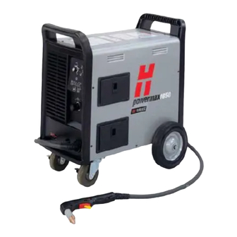
Note: Refer to Specifications – Power Supply to determine the duty cycle that corresponds with the input power. 8 minutes 2 minutes cutting resting Power Supply – Dimensions and Weight 16.8 in (427 mm) 26.4 in (671 mm) 124 lb (56.2 kg) 25.8 in (655 mm) Weight of power supply without torch powermax1650 Service Manual... -
Page 24: Specifications - T100 Torches
13.9 pounds (6.3 kg) with 50 ft (15 m) lead 8.3 pounds (3.8 kg) with 25 ft (7.5 m) lead T100M 11.0 pounds (5.0 kg) with 35 ft (10.7 m) lead 15.0 pounds (6.8 kg) with 50 ft (15 m) lead powermax1650 Service Manual... -
Page 25: Torch Dimensions
8.9" (226 mm) 4.2" (107 mm) 2.55" (65 mm) 1.5" (38 mm) 1.00" (25 mm) T100M Machine Torch Dimensions 1.00" 15.47" (25 mm) (393 mm) 2.35" 8" 1.38" (60mm) (203 mm) (35 mm) 32 pitch .125" (3.2 mm) width powermax1650 Service Manual... -
Page 26: Symbols And Markings
Plasma torch in the TEST position (cooling and cutting gas exiting nozzle) Plasma torch cutting and gouging Power is on AC input power connection Power is off The terminal for the external Volt/amp curve, "drooping" protective (earth) conductor characteristic powermax1650 Service Manual... - Page 27 SPECIFICATIONS powermax1650 Service Manual...
- Page 28 Visual Inspection – External ..........................3-5 Visual Inspection – Internal ..........................3-6 Resistance Checks ..............................3-7 Troubleshooting Guide..............................3-9 Voltage Checks...............................3-14 Component Replacement ............................3-20 Power Cord Replacement ..........................3-20 Torch Installataion ............................3-21 Filter Element Replacement...........................3-23 Work Cable Replacement ..........................3-24 Capacitor Replacement..........................3-25 Heat Sink Component Replacement......................3-26 powermax1650 Service Manual...
-
Page 29: Controls And Indicators
When illuminated, indicates that a fault condition exists, which prevents system operation. A yellow LED should also be illuminated that identifies the type of fault. Yellow Line Voltage LED When illuminated, indicates that line voltage is below 170 VAC, above 680 VAC, or missing a phase. powermax1650 Service Manual... -
Page 30: Theory Of Operation
The control board PCB3 includes a pilot arc control switch, allowing the operator to turn the pilot arc ON (useful when cutting expanded metal), OFF (for maximum life of consumables), or increase the pilot arc to 30A (useful for gouging or non-transferred-arc cutting). powermax1650 Service Manual... -
Page 31: Sequence Of Operation
• Select desired cutting amps with current • Depress plasma start switch on hand torch or adjustment knob. remote start switch for machine torch. • Gas solenoid valve V1 closes. Power circuits are ready. • Gas flow stops. powermax1650 Service Manual... -
Page 32: Troubleshooting
The complexity of the circuits requires that service technicians have a working knowledge of inverter power supply theory. In addition to being technically qualified, technicians must perform all testing with safety in mind. If questions or problems arise during servicing, call the nearest Hypertherm Technical Services Department listed in the front of this manual. -
Page 33: Visual Inspection - Internal
2. Remove the cover of the power supply by removing the 18 securing screws. 3. Inspect the inside of the power supply, especially on the side with the power board. Look for broken or loose wiring connections, burn and char marks, damaged components, etc. Repair or replace as necessary. powermax1650 Service Manual... -
Page 34: Resistance Checks
1. With the power disconnected, set the ON/OFF switch S1 to ON. 2. Check resistance across input leads. 3. Check resistance from input leads to ground. Note: All values are ±15%. 2.4 MΩ 2.4 MΩ 2.4 MΩ >20 MΩ powermax1650 Service Manual... - Page 35 • Value should be open with meter leads in one direction and 0.1V to 1.0V with meter leads reversed. Diode is shorted if value is less than 0.1V. Replace diode. Diode is open if value is greater than 1.0V in both directions. Replace diode. Linkage bar Note: Black marker on wire to lower diodes. powermax1650 Service Manual...
-
Page 36: Troubleshooting Guide
The Troubleshooting Guide provides most probable causes and solutions. Study the system wiring diagram and understand the theory of operation before troubleshooting. Before purchasing a major replacement component, verify the problem with Hypertherm Technical Service or the nearest Hypertherm repair facility. powermax1650... - Page 37 Problem This May Mean Cause Solution Turn power switch ON and Insufficient voltage to No voltage or improper voltage Verify incoming voltage is between 200-600 VAC. Power On LED does not control circuits or shorted applied to unit illuminate power component Defective power switch (S1) Measure AC voltage at bottom terminals of switch.
- Page 38 Yellow cap sensing LED Safety circuit not satisfied Consumables not installed, Refer to consumable diagram for proper installation. illuminates installed improperly, or Try new consumables. damaged Damage to safety circuit Remove torch. Check torch end of connector. Install consumables and check continuity on J18, pins 11 and 12 orange and blue wires.
- Page 39 When pressing torch Worn consumables Worn-out consumables Replace consumables trigger/start switch, pilot arc Improper air pressure Insufficient supply or air leak Turn current adjust knob to test flow and set pressure starts but “pops out” before setting or low flow on supply line regulator to 75 psi (5.2 bar) for cutting or 50 psi (3.4 the normal 5 second time-out...
- Page 40 START consumables are worn, or #3, in this section. control board (PCB3) position defective Pilot Arc IGBT Start and SP LEDs on control LED is for future use START board (PCB3) and Fault lamp are illuminated powermax1650 Service Manual 3-13...
-
Page 41: Voltage Checks
• Check input voltage to the input diode bridge. • The AC voltage between any 2 input wires should equal the line voltage. Note: All values are ±15%. = Line Voltage* = Line Voltage = Line Voltage* powermax1650 Service Manual 3-14... - Page 42 MAINTENANCE Voltage Check #2 • Check output voltage of the input diode bridge. • Output VDC = Line Voltage * 1.414 Note: All values are ±15%. Line Voltage * 1.414 powermax1650 Service Manual 3-15...
- Page 43 MAINTENANCE Voltage Check #3 • Check voltage across IGBT module (Q14). Note: All values are ±15%. 750 VDC powermax1650 Service Manual 3-16...
- Page 44 MAINTENANCE Voltage Check #4 • Check voltage across IGBT module (Q13). Note: All values are ±15%. 750 VDC 375 VDC 375 VDC powermax1650 Service Manual 3-17...
- Page 45 MAINTENANCE Voltage Check #5 • Check voltage across power supply capacitors. Note: All values are ±15%. 375 VDC powermax1650 Service Manual 3-18...
- Page 46 4. Pilot arc open – use a jumper wire to jump J14 to Q15. Then attempt to fire the torch. If the torch fires replace the Pilot Arc IGBT. Note: All values are ±15%. Pilot Arc IGBT powermax1650 Service Manual 3-19...
-
Page 47: Component Replacement
Route power cord through strain relief and tighten. Power Switch Strain relief Strain relief inserts (2) Ground (PE) Plug Installation The plug must be connected to the power cord by a licensed electrician. powermax1650 Service Manual 3-20... -
Page 48: Torch Installataion
MAINTENANCE Torch Installation Turn OFF power. Remove power cord from power receptacle. Open Easy Torch Removal (ETR) door and route lead through the end cap. Door End Cap powermax1650 Service Manual 3-21... - Page 49 Slide quick-release collar foward to lock the gas fitting in place. Make sure that the gas fitting is secure. Make sure that the red dot on the connector is on top, then plug in the electrical connector. Close ETR door. powermax1650 Service Manual 3-22...
-
Page 50: Filter Element Replacement
NOTE: Do not allow the filter element to turn when loosening the screw. Install filter bowl. A. Slide filter bowl over filter element. B. Align marks on filter bowl and filter body. C. Rotate filter bowl until it locks in place. powermax1650 Service Manual 3-23... -
Page 51: Work Cable Replacement
Tighten nut to 10 in-lb (12 kg cm) of torque. 4. Install ETR barrier 5. Install the power supply cover. CAUTION: This is a high-current connection. Proper torque is critical. Connect to J14 Strain Relief Barrier Work Cable powermax1650 Service Manual 3-24... -
Page 52: Capacitor Replacement
Tighten screws to 30 inch pounds (36 kg cm). Bleeder hole Install the power supply cover. Correct orientation of bleeder hole View hole Remove and install Remove and install screws capacitors from fan side. from power board side. powermax1650 Service Manual 3-25... -
Page 53: Heat Sink Component Replacement
Apply white thermal grease DC-340 (Part no. 027662) and torque to 35 in-lb (40 kg cm). Apply grey thermal grease TC-330 (Part no. 128836) and torque to 35 in-lb (40 kg cm). Note: grey thremal grease TC-330 is included with PFC IGBT Replacement Kit (Part no. 128745) powermax1650 Service Manual 3-26... -
Page 54: Parts - Power Supply
Section 4 PARTS - POWER SUPPLY In this section: Exterior ..................................4-2 Interior Right Side ..............................4-3 Back Interior Right side.............................4-4 Interior Fan Side ...............................4-5 Heat Sink Assembly ..............................4-6 Recommended Spare Parts .............................4-7 powermax1650 Service Manual... -
Page 55: Exterior
Current adjustment knob 110413 Control Panel Label 128735 End cap screws 123645 Ground clamp 011096 Regulator knob 128740 Power supply cover with labels, Domestic 128762 Power supply cover with labels, CE 128629 Cover screws 128742 Rear end panel powermax1650 Service Manual... -
Page 56: Interior Right Side
Pilot Arc IGBT Gate Drive Cable 128810 ETR Box 128622 Gas Manifold 046116 Tubing, 8mm OD, 6mm ID, nylon 3 ft. 108211 On/Off Knob 128665 Strain relief, arc voltage 128662 Machine interface 128737 Power PCB PCB2 123602 Gate Drive Cables powermax1650 Service Manual... -
Page 57: Back Interior Right Side
Power Supply – Back interior right side Part Item number Description Designator Quantity 128757 Front caster 128763 Rear axel 128764 Rear wheel replacement 128706 EMI filter PCB, CE only PCB1 128672 Power switch CSA 128761 Power switch CE powermax1650 Service Manual... -
Page 58: Interior Fan Side
Power Supply – Interior Fan Side Part Item Number Description Designator Qty. 128627 Filter bowl 011093 Air filter element 011094 O-ring 128749 Inductor, input choke 128741 Capacitor 128739 Power transformer 128749 Inductor, output choke 128683 Fan subassembly powermax1650 Service Manual... -
Page 59: Heat Sink Assembly
Output diode bridge 128747 Snubber resister assembly 128743 IGBT, inverter 128744 Temperature Switch PCB4 128745 IGBT, PFC 128746 Input diode bridge 128748 IGBT, pilot arc 128734 Snubber resister 129782 Snubber resister Reference page 3-26 for torque specifications. powermax1650 Service Manual... -
Page 60: Recommended Spare Parts
027662..........Thermal grease, 5 oz. DC-340 .................4-6 330080..........Thermal grease, 5 oz. TC-330................4-6 128733..........Output diode bridge ..................4-6 128747..........Snubber resister assembly ................4-6 128743..........IGBT, inverter....................4-6 128744..........Temperature Switch ..................4-6 128745..........IGBT, PFC......................4-6 128746..........Input diode bridge .....................4-6 128748..........IGBT, pilot arc ....................4-6 128734..........Snubber resister ....................4-6 129782..........Snubber resister ....................4-6 powermax1650 Service Manual... - Page 61 PARTS - POWER SUPPLY powermax1650 Service Manual...
-
Page 62: Parts List - Torch And Consumables
Section 5 PARTS LIST - TORCH AND CONSUMABLES In this section: T100 Hand Torch Assembly ............................5-2 T100M Machine Torch Assembly ..........................5-4 Torch Consumable Configurations..........................5-6 Recommended Spare Parts .............................5-8 powermax1650 Service Manual... -
Page 63: T100 Hand Torch Assembly
ETR Repair Kit (Regional Repair Centers only) 128642 Start Switch Replacement Kit * Top assembly includes the following consumables (See page 5-6 for details of consumable parts): 220051 Swirl Ring 220037 Electrode 220011 Nozzle 220048 Retaining Cap 220065 Shield powermax1650 Service Manual... - Page 64 PARTS – TORCH AND CONSUMABLES powermax1650 Service Manual...
-
Page 65: T100M Machine Torch Assembly
ETR Repair Kit (Regional Repair Centers only) 128645 Torch Mounting Kit (for reassembly after installation) * Top assembly includes the following consumables (See page 5-6 for details of consumable parts): 220051 Swirl Ring 220037 Electrode 220011 Nozzle 220048 Retaining Cap 220047 Shield powermax1650 Service Manual... - Page 66 PARTS – TORCH AND CONSUMABLES powermax1650 Service Manual...
-
Page 67: Torch Consumable Configurations
Retaining Cap Nozzle 120929 120928 120932 O-Ring 058519 120926 120925 120929 120928 120931 120929 120928 120927 100A 220037 220051 220065 220048 220011 O-Ring 058519 120977 120928 220059 120926 120925 120977 120928 120978 100A 220037 220051 120977 220048 220063 powermax1650 Service Manual... - Page 68 Maintain torch-to-work distance of 120979 120928 220006 approximately 3/16 inch (4.8 mm). O-Ring 058519 120979 120928 220007 120926 120925 120979 120928 120980 100A 120979 220048 220064 220037 220051 powermax1650 Service Manual...
-
Page 69: Recommended Spare Parts
T100M Machine Torch Replacement Lead 25 ft (7.6 m) 128751 T100M Machine Torch Replacement Lead 35 ft (10.7 m) 128759 T100M Machine Torch Replacement Lead 50 ft (15.2 m) 128643 Torch Mounting Sleeve Replacement Kit 128645 Torch Mounting Kit (for reassembly after installation) powermax1650 Service Manual... -
Page 70: Wiring Diagrams
Section 6 WIRING DIAGRAMS In this section: Timing Diagrams...............................6-2 Electrical Schematic ..............................6-4 powermax1650 Service Manual... -
Page 71: Powermax1650 Service Manual
Re-Seat Pcritical(15) Time Gas Pressure Constant at Torch (psi) tdelay Voltage (volts) ~ ~ 10ms I Setpoint 2.17A/ms (amps) I Work Lead If >5.0 sec Digitized pilot arc time out XFR signal in DSP and Machine Motion powermax1650 Service Manual... - Page 72 NOTE: UNIT IS ALREADY IN TRANSFER MODE ~ 3FFh Digitized MUST BE >10ms Must be < 28us Setpoint Setpoint 21.5A Icommand Reattach Digitized causes XFR signal transfer in DSP If >10.00 sec CPA timeout I SETPOINT 2.17A/ms I work lead 30A 1.6A 0.4A powermax1650 Service Manual...
- Page 73 POWER BD PCB2 PFC CHOKE DOMESTIC UNIT K1, K2 Vbus IGBT SOFT START INVERTER CORD 129773 C100 INPUT VacR Vbus POWER BRIDGE CONTROL TRANSFORMER IGBT (PE) FLYBACK SYSTEM 18PA POWER CONTROL 30 OHM SUPPLY COMPA 100W 18INV -6INV 7.5 ohm 100W COMT 18REG...
Need help?
Do you have a question about the powermax1650 and is the answer not in the manual?
Questions and answers