Milwaukee MA887 Manual
- Instruction manual (16 pages) ,
- Instruction manual (146 pages)
Advertisement
- 1 FUNCTIONAL DESCRIPTION
- 2 GENERAL DESCRIPTION
- 3 SPECIFICATIONS
- 4 PRINCIPLE OF OPERATION
- 5 MEASUREMENT GUIDELINES
- 6 CALIBRATION PROCEDURE
- 7 MEASUREMENT PROCEDURE
- 8 CHANGING MEASUREMENT UNIT
- 9 CHANGING TEMPERATURE UNIT
- 10 MAKING A STANDARD SODIUM CHLORIDE SOLUTION
- 11 ERROR MESSAGES
- 12 BATTERY REPLACEMENT
- 13 RECOMMENDATION
- 14 WARRANTY
- 15 Documents / Resources
Remove the instrument from the packing materials and examine carefully to ensure no damage has occurred during shipping. If any damage has occurred, notify your Dealer.
Each instrument is supplied with:
- Ÿ9 V battery
- ŸInstruction manual
 Note: Save all packing material until you are sure that the instrument functions correctly. A defective instrument must be returned in its original packing.
FUNCTIONAL DESCRIPTION
DISPLAY

- BATTERY STATUS ICON (BLINKS WHEN LOW BATTERY CONDITION DETECTED)
- MEASUREMENT IN PROGRESS TAG
- SETUP: FACTORY CALIBRATION TAG
- CAL: CALIBRATION TAG
- AUTOMATIC TEMPERATURE COMPENSATION (BLINKS WHEN TEMPERATURE EXCEEDS 10-40°C / 50-104°F RANGE)
- PRIMARY DISPLAY (DISPLAYS MEASUREMENT AND ERROR MESSAGES)
- TEMPERATURE UNITS
- SECONDARY DISPLAY (DISPLAYS TEMPERATURE MEASUREMENTS; WHEN BLINKING, TEMPERATURE HAS EXCEEDED OPERATION RANGE: 0-80°C / 32-176°F)
- RANGE INDICATOR
FRONT PANEL

- LIQUID CRYSTAL DISPLAY (LCD)
- READ KEY (USER MEASUREMENT)
- ZERO KEY (USER CALIBRATION)
- RANGE KEY (USER MEASUREMENT UNIT)
- ON/OFF
- STAINLESS STEEL SAMPLE WELL AND PRISM
- SECONDARY DISPLAY
- PRIMARY DISPLAY
BOTTOM

- BATTERY COVER
- BATTERY COMPARTMENT
GENERAL DESCRIPTION
SIGNIFICANCE OF USE
Thank you for choosing Milwaukee. This instruction manual will provide you the necessary information for correct use of the meter.
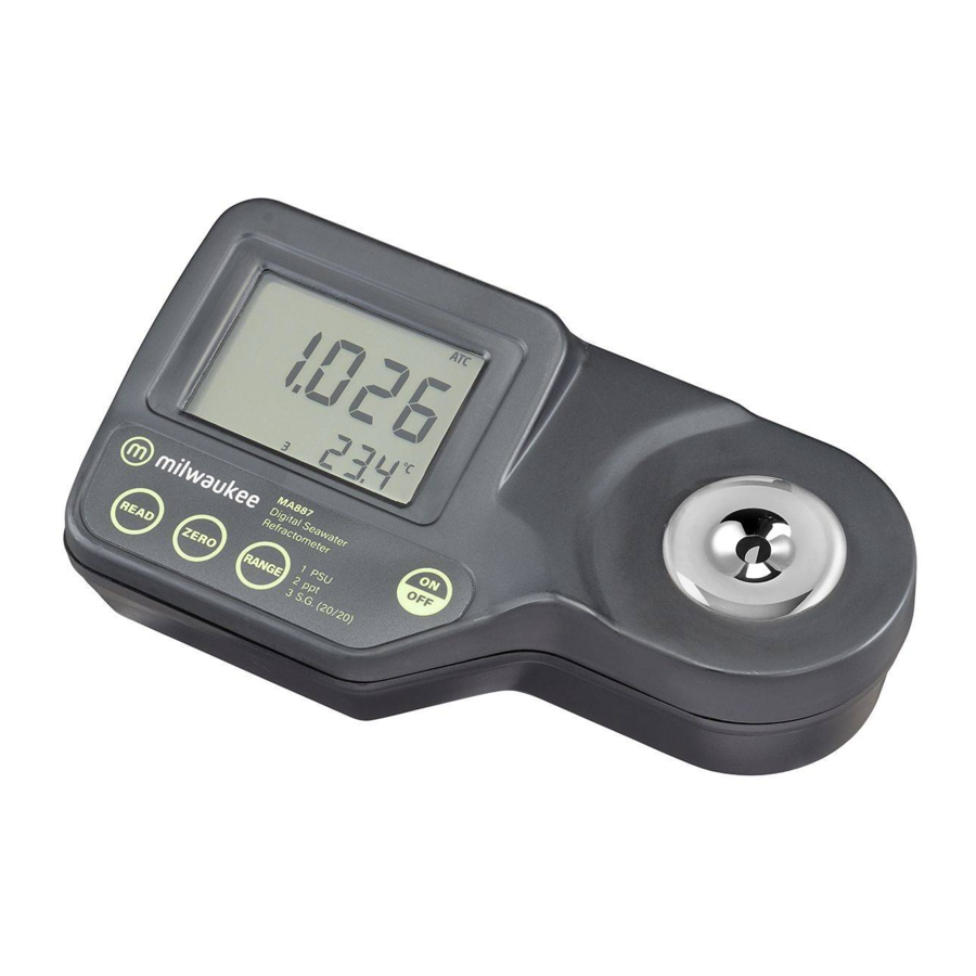
The MA887 is an optical instrument that employs the measurement of the refractive index to determine the salinity of natural and artificial seawater, ocean water or brackish intermediates. The digital refractometer eliminates the uncertainty associated with mechanical refractometers and is easily portable for ship, shore or home use.
The MA887 refractometer is an optical device that is simple and quick to use. Samples are measured after a simple user calibration with distilled or deionized water. Within seconds, the refractive index and temperature are measured and converted into one of three popular measurement units; Practical Salinity Units (PSU), Salinity in parts per thousand (ppt), or Specific Gravity (S.G. (20/20)). All conversion algorithms are based upon respected scientific publications using the physical properties of seawater (not sodium chloride). The temperature (in °C or °F) is also displayed on the large dual level display along with helpful message codes.
Key features include:
- ŸWaterproof models offers IP65 waterproof protection
- ŸAutomatic Temperature Compensation (ATC)
- ŸBattery operation with Low Power indicator
- ŸAutomatically turns off after 3 minutes of non-use.
SPECIFICATIONS
| PSU | ppt | S.G. (20/20) | °C (°F) | |
| Range | 0 to 50 | 0 to 150 | 1.000 to 1.114 | 0 to 80°C (32 to 176°F) |
| Resolution | 1 | 1 | 0.001 | 0.1°C (0.1°F) |
| Accuracy | ±2 | ±2 | ±0.002 | ±0.3°C (±0.5°F) |
| Light Source | Yellow LED |
| Measurement Time | Approximately 1.5 seconds |
| Minimum Sample Volume | 100 µL (cover prism totally) |
| Sample Cell | Stainless Steel ring and flint glass prism |
| Temperature Compensation | Automatic between 0 and 40°C (32 to 104°F) |
| Case Material | ABS |
| Enclosure Rating | IP 65 |
| Battery Type/Life | 1 x 9 volt AA batteries / 5000 readings |
| Auto-Shut off | After 3 minutes of non-use |
| Dimensions | 19.2 x 10.2 x 6.7 cm (7.5 x 4 x 2.6") |
| Weight | 420 g (14.8 oz.). |
PRINCIPLE OF OPERATION
Salinity determinations are made by measuring the refractive index of seawater. Refractive Index is an optical characteristic of a substance and the number of dissolved particles in it. Refractive Index is defined as the ratio of the speed of light in empty space to the speed of light in the substance. A result of this property is that light will "bend", or change direction, when it travels through a substance of different refractive index. This is called refraction.
When passing from a material with a higher to lower refractive index, there is a critical angle at which an incoming beam of light can no longer refract, but will instead be reflected off the interface.

The critical angle can be used to easily calculate the refractive index according to the equation:

Where n2 is the refractive index of the lower-density medium; n1 is the refractive index of the higher-density medium.

In the MA887 refractometer, light from an LED passes through a prism in contact with the sample. An image sensor determines the critical angle at which the light is no longer refracted through the sample. Specialized algorithms then apply temperature compensation to the measurement and convert the refractive index to: PSU (Practical Salinity Units), ppt (part per thousand) or S.G. (Specific Gravity) (20/20). PSU is defined as the conductivity ratio of seawater to a standard KCl solution. It is based upon the work of the UNESCO, ICES, SCOR and IAPSO. This information is published in The Joint Panel of Oceanographic Tables and Standards. An older salinity scale is ppt (10-3), where salinity is defined by "the salt content is the weight of the inorganic salts contained in 1 kg of seawater if all bromide and iodide are replaced by an equivalent amount of oxides" (Knudsen, 1901).
Specific Gravity (20/20) ia based upon the published relationship between density at 20°C and the mass of dissolved salts in the seawater sample (CRC Handbook of Chemistry and Physics, 87th) Edition).
MEASUREMENT GUIDELINES
- Handle instrument carefully. Do not drop.
- Do not immerse instrument under water.
- Do not spray water to any part of instrument except the "sample well" located over the prism.
- The instrument is intended to measure seawater solutions. Do not expose instrument or prism to solvents that will damage it. This includes most organic solvents and extremely hot or cold solutions.
- Particulate matter in a sample may scratch the prism. Absorb sample with a soft tissue and rinse sample well with deionized or distilled water between samples.
- Use plastic pipettes to transfer all solutions. Do not use metallic tools such as needles, spoons or tweezers as these will scratch the prism.
- Cover sample well with hand if measuring in direct sun.
CALIBRATION PROCEDURE
Calibration should be performed daily, before measurements are made, when the battery has been replaced, between a long series of measurements, or if environmental changes have occurred since the last calibration.
- Press the ON/OFF key, then release. Two instrument test screens will be displayed briefly; all LCD segments followed by the percentage of remaining battery life. The meter will then briefly display an indication of the measurement unit set. When the LCD displays dashes, the instrument is ready.

- Using a plastic pipette, fill the sample well with distilled or deionized water. Make sure the prism is completely covered.


Note: If the ZERO sample is subject to intense light such as sunlight or another strong source, cover the sample well with your hand or other shade during the calibrationPress the ZERO key. If no error messages appear, your unit is calibrated. (For a description of error messages see ERROR MESSAGES section).

Note: The 0 screen will remain until a sample is measured or the instrument is turned off.
- Gently absorb the ZERO water standard with a soft tissue. Use care not to scratch the prism surface. Dry the surface completely. The instrument is ready for sample measurement.
![]()

Note: If instrument is turned off the calibration will not be lost.
MEASUREMENT PROCEDURE
Verify the instrument has been calibrated before taking measurements.
- Wipe off prism surface located at the bottom of the sample well. Make sure the prism and sample well are completely dry.
![]()
- Using a plastic pipette, drip sample onto the prism surface. Fill the well completely.
![]()


Note: If the temperature of the sample differs significantly from the temperature of the instrument, wait approximately 1 minute to allow thermal equilibration.
- Press the READ key. The results are displayed in unit of interest.


Note: The last measurement value will be displayed until the next sample is measured or the instrument is turned off.
Temperature will be continuously updated.
Note: The "ATC" tag blinks and automatic temperature compensation is disabled if the temperature exceeds the 0-40°C / 32-104°F range.
- Remove sample from the sample well by absorbing on a soft tissue.
- Using a plastic pipette, rinse prism and sample well with distilled or deionized water. Wipe dry. The instrument is ready for the next sample.


CHANGING MEASUREMENT UNIT
Press the RANGE key to select measurement units. The instrument toggles between the three measurement scales each time the key is pressed and the primary display indicates "PSU", "PPt" and "S.G.". When the instrument displays the screen with 4 dashes, the instrument is ready for measurement. A number on the display indicates the selected unit: "1" denotes PSU, "2" denotes ppt and "3" denotes Specific Gravity.

CHANGING TEMPERATURE UNIT
To change the temperature measurement unit from Celsius to Fahrenheit (or vice versa), follow this procedure.
- Press and hold theON/OFF key continuously for approximately 8 seconds. The LCD will display the "all segment" screen followed by a screen with the model number on the primary display and the version number on the secondary display. Continue pressing the ON/OFF key.

- While continuing to hold theON/OFF key, press the ZERO key.


The temperature unit will change from °C to °F or vice versa.
MAKING A STANDARD SODIUM CHLORIDE SOLUTION
Sodium Chloride solutions can be used to check the accuracy of the meter. The table below lists two Sodium Chloride solutions and their expected ppt Seawater value.
To make a Standard NaCl Solution (g/100 g) follow the procedure below:
- Place container (such as a glass vial or dropper bottle that has a cover) on an analytical balance.
- Tare the balance.
- To make an X NaCl solution weigh out X grams of high purity dried Sodium Chloride (CAS #: 7647-14-5; MW 58.44) directly into the container.
- Add distilled or deionized water to the container so the total weight of the solution is 100 g.
| g of NaCl | g of Water | Total Weight | Expected ppt Seawater Value | |
| 3.5% NaCl | 3.50 | 96.50 | 100.00 | 34 |
| 10% NaCl | 10.00 | 90.00 | 100.00 | 96 |
ERROR MESSAGES
| Error Code | Description | |
| Err |  | General failure. Cycle power to instrument. If instrument still has error, contact Milwaukee. |
| LO Primary display |  | Sample is reading lower than the 0 standard used for meter calibration. |
| HI Primary display |  | Sample exceeds maximum measurement range. |
| LO Primary display CAL segment ON |  | Wrong calibration used to zero instrument. Use deionized or distilled water. Press Zero. |
| HI Primary display CAL segment ON |  | Wrong calibration used to zero instrument. Use deionized or distilled water. Press Zero. |
| t LO Primary display CAL segment ON |  | Temperature exceeds ATC low limit (0°C) during calibration. |
| t HI Primary display CAL segment ON |  | Temperature exceeds ATC high limit (40°C) during calibration. |
| Air |  | Prism surface insufficiently covered. |
| ELt |  | Too much external light for measurement. Cover sample well with hand. |
| nLt |  | LED light is not detected. Contact Milwaukee. |
| Battery segment blinking |  | <5% of battery life is remaining. |
| Temperature values are blinking 0.0°C or 80.0°C |  | Temperature measurement out of sampling range (0.0 to 80.0°C). |
| ATC segment blinking |  | Outside temperature compensation range (0 to 40°C). |
| SETUP segment blinking |  | Factory calibration lost. Contact Milwaukee. |
BATTERY REPLACEMENT
To replace the instrument's battery, follow these steps:
- Turn the instrument OFF by pressing the ON/OFF key.
![]()
- Turn instrument upside down and remove the battery cover by turning it counterclockwise.

- Extract the battery from its location.
- Replace with fresh 9V battery making certain to observe polarity.
- Insert the back battery cover and fasten it by turning clockwise to engage.


RECOMMENDATION
Before using this product, make sure it is entirely suitable for your specific application and for the environment in which it is used. Any modification introduced by the user to the supplied equipment may compromise the meter's performance. For your and the meter's safety do not use or store the meter in hazardous environment. To avoid damage or burn, do not perform any measurement in microwave ovens.
WARRANTY
These instruments are warranted against defects in materials and manufacturing for a period of 2 years from the date of purchase. Electrodes and Probes are warranted for 6 months. This warranty is limited to repair or free of charge replacement if the instrument cannot be repaired. Damage due to accidents, misuse, tampering or lack of prescribed maintenance is not covered by warranty. If service is required, contact your local Milwaukee Instruments Technical Service. If the repair is not covered by the warranty, you will be notified of the charges incurred. When shipping any meter, make sure it is properly packaged for complete protection.
Documents / ResourcesDownload manual
Here you can download full pdf version of manual, it may contain additional safety instructions, warranty information, FCC rules, etc.
Advertisement


Need help?
Do you have a question about the MA887 and is the answer not in the manual?
Questions and answers