
Related Manuals for wiwa DUOMIX GLASSFLAKE GX


Summary of Contents for wiwa DUOMIX GLASSFLAKE GX
- Page 1 Operation Manual DUOMIX GLASSFLAKE GX Serial No.: 2dmgf_BA_en_B0550050 ✓(2024/04/08)
-
Page 2: Ec Declaration Of Conformity
EC declaration of conformity in accordance with Annex II, No. 1 A of Machine Directive 2006 / 42 / EC, as amended by 2009 / 127 / EC The company WIWA Wilhelm Wagner GmbH & Co. KG 35633 Lahnau Gewerbestraße 1–3 Germany... -
Page 3: Eu Declaration Of Conformity
EU declaration of conformity in accordance with ATEX Directives The company WIWA Wilhelm Wagner GmbH & Co. KG 35633 Lahnau Gewerbestraße 1–3 Germany hereby declares that the machine DUOMIX GLASSFLAKE GX type with serial no. conforms with the provisions of Directive 2014 / 34 / EU. -
Page 5: Table Of Contents
Contents Contents 1 Foreword 2 Safety 2.1 Explanation of symbols ......2.2 Safety notes ....... 2.2.1 Working pressure . - Page 6 Contents 3.12.2 Lifts ....... 31 3.12.3 Agitator pneumatic shut-off valve ....32 3.12.4 Feed pumps .
- Page 7 Contents 6.5.4 Replacing the packing ..... 65 6.6 Beam pumps ......66 6.7 Feed pump (optional) .
-
Page 9: Foreword
If questions should arise, we would be happy to assist you. We wish you excellent working results with your machine WIWA Wilhelm Wagner GmbH & Co. KG Copyright © 2025 WIWA The copyright to this operation manual belongs to WIWA Wilhelm Wagner GmbH &... -
Page 10: Safety
We recommend that the machine owner have this confirmed in writing. 2.1 Explanation of symbols Safety notes warn of potential accident risks and describe the measures required for accident prevention. In the WIWA operation manuals, safety notes are high- lighted and labeled as follows: DANGER... - Page 11 Safety General risk of accident Risk of explosion due to explosive atmosphere Risk of explosion due to explosive substances Risk of accident due to electricity or electrostatic charge Warning of crushing Warning of corrosive substances Risk of injuries due to rotating machine parts Risk of burning due to hot surfaces Risk of freezing due to cold surfaces The first line of the safety instructions indicates the personal protective equipment...
-
Page 12: Safety Notes
Safety Wear protective gloves Signals an instruction to wear protective gloves in order to prevent injuries due to aggressive chemicals, burns when processing heated materials, or freezing due to contact with very cold surfaces. Wear safety shoes Signals an instruction to wear safety shoes, in order to prevent foot injuries due to falling, toppling or rolling objects, as well as slipping on slippery floors. -
Page 13: Working Pressure
Safety 2.2.1 Working pressure WARNING Parts that are not designed for the maximum permissible working pressure may rupture and cause serious injuries. It is essential to observe the prescribed maximum working pressures for all parts. With varying working pressures, the lowest value always applies as the maximum working pressure for the complete machine. -
Page 14: Risk Of Crushing
Never spray solvents or materials containing solvents into narrow-mouthed cans or drums with a bung opening! Only use electrically conductive material hoses. All original material hoses from WIWA are conductive and designed for our devices. Only use electrically conductive accessories/accessory parts. WARNING Dirty machines can become electrostatically charged. -
Page 15: Explosion Protection
Safety 2.2.5 Explosion protection The following short designations are used in the instructions of WIWA: Ex protection: Explosion protection Ex area: potentially explosive or non-explosion protected area Non-Ex area: non-explosive or explosion protected area Ex zone: Explosion protection zone according to ATEX Directive... -
Page 16: Risks Due To Rotating Parts
Safety WARNING During the lifting movement, loose items of clothing may come between the drum cover and the material drum or be caught on other machine parts, and be pulled into the container or upwards. Wear tight-fitting clothing with low tear-resistance, tight sleeves and no pro- jecting parts. -
Page 17: Health Risks
Safety WARNING Loose articles of clothing or long hair can be caught by rotating parts. Wear tight-fitting clothing with low tear-resistance, tight sleeves and no pro- jecting parts. Tie back long hair and wear a head covering. Remove jewelry, including rings. CAUTION Material can spray out during operation. -
Page 18: Safety Signs
Safety 2.3 Safety signs The safety signs attached to the ma- chine, such as the orange tag (see Fig. 2), indicate possible dangers and must be observed. By scanning the QR code, the most important safety information for this machine can be accessed. Also read and observe the safety notes in the operation manual! Additional symbols on the machine... -
Page 19: Compressed Air Shut-Off Valve
Safety Checklist: Seal on the safety valve OK? Safety valve externally free of damage? Ground cable free of damage? Connections of the ground cable to the machine and to the conductor OK? Function of the compressed air shut-off valve OK? Function of the automatic shut-off OK? (only on model with feed system and agitator) When checking additional safety features, observe the operation manuals for... -
Page 20: Rupture Disc Pressure Protection
Safety 2.4.2 Rupture disc pressure protection A rupture disc is installed under the contact pressure gauge on the mixing unit. Rupture discs are pressure protection with a disposable membrane. If the permissible material pressure is clearly exceeded, the membrane bursts and the ma- terial escapes into the connected collecting vessel. -
Page 21: Safety Valves
Safety 2.4.4 Safety valves Safety valves are located on the ma- chine on the air motor: the component A dosing pump (behind the covering of the muffler) of the flush pump of the feed pump (optional) The safety valves prevent the max- imum permissible air inlet pressure from being exceeded. -
Page 22: Ground Cable
Safety The proportioning system is equipped with protective grating in the mounting area of the beam pump to the high pressure pump. The protective grating covers movable parts on both pumps. Fig. 7: Protective grating on the proportioning system The protective grating in the feed container for component A protects against contact with rotating parts. -
Page 23: Pneumatic Agitator Shutoff
Fig. 10: Pneumatic valve 2.4.8 Automatic shut-off for the agitator The DUOMIX GLASSFLAKE GX can be optionally equipped with a mate- rial feed system including agitator. As soon as the drum cover or holder lifts... -
Page 24: Personnel Qualifications
Safety 2.5.2 Personnel qualifications Differentiation is made between two groups of personnel, depending on their qualifications: Instructed operators have received verified instruction from the machine owner regarding the tasks entrusted to him and the possible risks if the correct procedure is not followed. Trained personnel have received instruction provided by the machine manu- facturer and are capable of carrying out maintenance and repair work on the machine, independently recognizing possible dangers and avoiding risks. -
Page 25: Warranty And Liability
When repairing and maintaining the machine, original spare parts from WIWA must be used. If spare parts are used that have not been produced or supplied by WIWA, the warranty is void and all liability shall be excluded. 2.6.2 Accessories If you use original WIWA accessories, their suitability for use in our machines is guaranteed. -
Page 26: Failure Of The Power Supply
Safety 1. Actuate the emergency stop / main compressed air shut-off valve section 2.4.1 on page 11. The pressure relief occurs via a non-return valve with ventilation function. 2. Lock the trigger of the spray gun. 3. Disconnect the machine from the energy supply: Press the emergency stop button on the control cabinet for the pressure and dosing control to interrupt the power supply of the machine and prevent uncontrolled start-up when the power supply is restored. -
Page 27: Leakage
Safety 2.7.3 Leakage WARNING In case of leakage, material may escape under very high pressure and cause serious physical injuries and property damage. Stop the machine immediately and relieve the pressure. Tighten threaded connections and replace defective parts (must be performed by trained personnel). -
Page 28: Description
WIWA (see section 2.6.1 on page 17), accessories are used that are not suitable for the machine (see section 2.6.2... -
Page 29: Construction
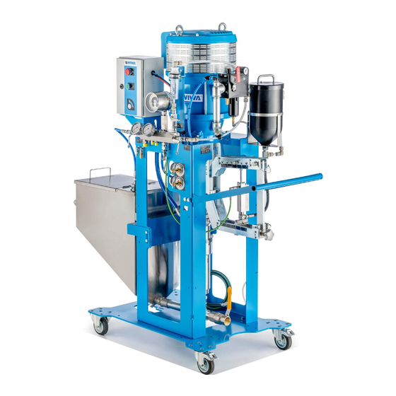
Description 3.3 Construction Fig. 12: Example of a DUOMIX GLASSFLAKE GX Designation For details, see (Air motor for the) proportioning pump section 3.7 on page 24 Control cabinet for pressure and dosing section 3.4 on page 22 control Intermediate piece section 3.8 on page 26... -
Page 30: Pressure And Dosing Control
Description Designation For details, see Compressed air regulation unit section 3.6 on page 23 Handle Beam pump / fluid pump for component B section 3.7 on page 24 Frame (here: cart) Material drain cock for component A section 3.11 on page 28 3.4 Pressure and dosing control Designation and function With “Stop”... -
Page 31: Compressed Air Supply
Description 3.5 Compressed air supply All compressed air driven modules of the machine are centrally supplied with compressed air via the maintenance unit. The connection of the compressed air line provided by the owner occurs at the compressed air connection. The compressed air supply for the entire machine is opened or interrupted with the compressed air shut-off valve. -
Page 32: Proportioning Pump With Beam Pump
Description Designation Symbol Pressure gauge for the flush pump pressure display Pressure gauge for proportioning pump pressure display component A Compressed air regulator for component A propor- tioning pump Compressed air regulator for flush pump The functional principle of all com- pressed air regulators installed on the machine is the same: To increase the pressure,... - Page 33 Description Fig. 17: Proportioning pump (example) Designation Muffler of the air motor Compressed air inlet / connection for maintenance unit (section 6.3 on page 61) Protective grating Material outlet for component B (hidden) Piston pump for component B Lever of the beam system Material inlet for component B Original Operation Manual ✓(2024/04/08), Status: 2025/01/09 2dmgf_BA_en_B0550050...
-
Page 34: Intermediate Piece
Description Designation Release agent vessel of the fluid pump Material outlet for component A 11/12 Material inlet for component A Safety valve Fastening pins of the lever (7) Star knob for adjusting (section 5.1.8 on page 48) To manually operate the piston pump for component B, remove the pins (14) and attach the lever (7) as a handle to the upper beam of the beam system (Fig. -
Page 35: Flush Pump
Description Designation Flushing material hose connection Connection for the component B material hose Bursting disk safety device and connection for return flow hose of B component to container Ball valve for circulating component B Connection for the component B return flow hose “Ratio check B component ball valve”... -
Page 36: Mixing Unit
Description 3.10 Mixing unit Designation Pressure gauge for com- ponent A pressure display (optional) Pressure gauge for com- ponent B pressure display (optional) Material discharge ball valve for component B Flushing ball valve for compo- nent B Spraying ball valve Static mixer Flushing ball valve for compo- nent A... - Page 37 Description Description Filler opening with safety guard Cover Pneumatically-driven agitator Compressed air connection and compressed air shut-off valve on the agitator Connection for return flow hose Container Connection for suction of the high pressure pump Material discharge ball valve Fig. 21: Feed container with agitator Open the material discharge ball valve only to empty the feed container or to remove blockages at the suction.
-
Page 38: Optional Expansions And Accessories
The detailed accessory catalog can be found at www.wiwa.de. For further infor- mation and order numbers, you can also contact an approved WIWA dealer or WIWA customer service. Observe and follow the separate operation manuals for all accessories used. -
Page 39: Lifts
Level monitoring Feed pumps To fill the feed container of the DUOMIX GLASSFLAKE GX, a material hose is held in the container by the feed pump on the feed system. When the feed pump is running, the material flow can be released or stopped with a material shut-off valve. -
Page 40: Agitator Pneumatic Shut-Off Valve
Description Fig. 24: Lift control Fig. 25: Throttle screws Designation Information Control lever for the lift The lift moves up. STOP: The lift stops. The lift moves down. Button for releasing the agitator Button pressed ⇒ agitator is released, Button released ⇒ agitator is switched off, Compressed air shut-off valve for lift and agitator... -
Page 41: Feed Pumps
Description Fig. 27: Shut-off valve symbolic Fig. 26: Shut-off valve Fig. 28: Pneumatic valve image On / Off 3.12.4 Feed pumps Feed pumps can also be used in material feed systems. Feed pumps are con- nected to the compressed air supply via a compressed air distributor and are controlled via a separate compressed air regulator. -
Page 42: Drum Cover
Description 3.12.5 Drum cover Drum covers are used for accommodating attachments, such as a feed pump (pis- ton or membrane pump), an electrically or pneumatically-driven agitator or level sensors. Drum covers can be used individually or in combination with lifts (section 3.12.2). They are placed on the edge of the container used and thus close it. -
Page 43: Pneumatic Agitator
Pneu- matic agitators are supplied with com- pressed air via the maintenance unit of the DUOMIX GLASSFLAKE GX. The rotation speed is controlled with the adjusting screw on the air intake of the agitator. -
Page 44: Transport, Installation, And Assembly
Transport, installation, and assembly 4 Transport, installation, and assembly The machine left the factory in faultless condition, packaged correctly for transport. Check the machine at the time of receipt for any transport damage and for com- pleteness. 4.1 Transport The machine can be mounted to a movable frame with a lockable front castor, in order to facilitate transport. -
Page 45: Installation Site
Transport, installation, and assembly Disconnect the entire energy supply to the machine - even for short transport distances. Wait for moving parts to come to a standstill. Empty the machine prior to transport - residual liquids may still leak out of the machine during transport. -
Page 46: Assembly
Transport, installation, and assembly Always observe and follow the safety data sheets and processing instructions of the material manufacturer. Even if legal regulations do not apply to the low-mist airless spray process, dangerous solvent vapors and paint particles must be extracted. Protect all items neighboring the spray object against possible damage due to paint mist. -
Page 47: Connecting The Hose Bundle
Transport, installation, and assembly 4.3.1 Connecting the hose bundle WARNING If the connections for the hose bundle are subjected to strain, these may be torn out. The material escaping under high pressure may cause injuries and damage to property. If tensile forces are anticipated on the hose bundle connections (for example, due to the positioning of the mixing unit), it is necessary to utilize strain relief! If the hose bundle is too tightly curved, the hoses in the hose bundle may become kinked. -
Page 48: Connecting The Spraying Hose And Spray Gun
It must be greater than or equal to the maximum working pressure stated on the type plate. Connect the selected spray gun (e.g. WIWA 500D airless gun) to the static mixer using an appropriate material hose (see also section 3.10 on page 28). -
Page 49: Grounding The Machine
Transport, installation, and assembly 4.3.3 Grounding the machine WARNING The high flow velocities during operation can result in an electrostatic charge. Static discharges can result in fire and explosions. Ensure that the machine is properly grounded outside of Ex zones! Ensure correct grounding of the object to be coated. -
Page 50: Operation
Operation 5 Operation Before starting to work, check: Are all safety features present and fully functional? Are all machine parts leak-tight? Retighten the connections if necessary; observe the tightening torques in the spare parts lists if necessary. WARNING If fluid pumps run dry, this can lead to fire or an explosion due to the resulting friction heat. -
Page 51: Switching On The Machine
Operation 5.1.1 Switching on the machine 1. Make sure that all compressed air shut-off valves are closed and all compressed air regulators are turned all the way down. 2. Open the compressed air shut-off valve on the maintenance unit. 3. Unlock the emergency stop button on the control cabinet. 4. -
Page 52: Flushing Out The Remains Of The Test Substance
Operation 5.1.3 Flushing out the remains of the test substance Following assembly, the machine was tested in the factory for faultless function with a test substance. During initial commissioning, it is therefore necessary to first completely clean the machine to flush out the remaining test substance (section 5.4 on page 53). - Page 53 Operation 6. Set the compressed air regulator for the proportioning pumps (section 3.6 on page 23) such that the proportioning pump of component A runs slowly. 7. Switch the machine to circulation mode: Make sure that all ball valves on the external mixing unit are closed. Open both ball valves for the circulation on the intermediate piece (see section 3.8 on page 26).
-
Page 54: Putting The Material Feed System Into Operation
Operation 5.1.5 Putting the material feed system into operation The use and design of a material feed system is optional and customer-specific. Therefore, separate operation manuals are provided for the machines associated with the system. Observe and follow the separate operation manuals for your material feed system, e.g. -
Page 55: Filling The Hose Bundle
Operation 5.1.6 Filling the hose bundle 1. Move the lever of the beam pump (section 5.1.4 on page 44) up and down until the processing material escapes from the return flow hose evenly. 2. Reassemble the return flow hose for component B on the intermediate piece. 3. -
Page 56: Adjusting The Proportioning Quantity For Component B (Beam Pump)
Operation 5. Set the compressed air regulator for the proportioning pumps (section 3.6 on page 23) such that the proportioning pump of component A runs slowly and material escapes. 6. Once 1 l of component A has run into the measuring cup, close the ball valve for the circulation of component A. -
Page 57: Coating
Operation 1. If there is a slight deviation from the desired mixing ratio, adjust the beam pump on the bottom suspen- sion using the star knob. 2. If larger changes in the mixing ra- tio are necessary, also adjust the beam pump on the upper beam. -
Page 58: Setting The Spraying Pressure
Operation 8. Regulate the air inlet pressure of the piston pump to the desired spraying pressure (see information in section 5.2.1 on page 50). 9. Check the limits for the pressure monitoring of component B (section 5.2.2 on page 50). If the pointer of the pressure monitoring pressure gauge does not move or only moves insufficiently, the machine may not be put into operation. - Page 59 Operation 1. Slide the key provided into the contact pressure gauge. 2. Using the guide needle, turn the bottom red - 20 bar drag indicator to a value approx. 20 bar below the lowest pressure, which is displayed when the spray gun is open. + 20 bar 3.
-
Page 60: Tips For Good Coatings
Operation 5.2.3 Tips for good coatings Hold the spray gun at a right angle (90°) to the surface to be coated. As soon as you hold the spray gun at a different angle, the coating will become uneven and patchy (see Fig. -
Page 61: Cleaning The Machine Completely
Operation 4. Open the flushing ball valve for component A on the mixing unit (see sec- tion 3.10 on page 28). 5. The flush pump should still be under pressure (see section 5.1.2 on page 43). If not, regulate the air pressure to 2 bar (see section 3.6 on page 23). 6. - Page 62 Operation The area from the material inlet to the mixing unit will be cleaned during the next work steps. Both components must also be strictly separated during cleaning. Use a separate collecting vessel for each component in order to prevent material reactions and damage to the machine.
-
Page 63: Pressure Relief
The machine has been specially configured for your application case. It is necessary to check compatibility of the materials used with other materials in each individual case. WIWA is happy to help determine the suitability of your machine for another material. -
Page 64: Decommissioning
Operation 5.7 Decommissioning For a short-term decommissioning (e.g. end of work / shift end: work will resume the following day), flush the machine according to the instructions in section 5.3. When decommissioning with a longer downtime, the material must be emptied out of the containers and then the machine must be flushed. -
Page 65: Brief Work Interruption
Operation 16. Close all levers on the mixing unit (see Fig. 20 on page 28) The cleaning agent remains in the machine for the duration of the decommissioning. When recommissioning, flush it out again by filling the machine (see section 5.1.4 on page 44). -
Page 66: Disposal
Operation 5.9 Disposal Residues of processing material, flushing agents, oils, greases and other chemi- cal substances must be collected according to the legal regulations for recycling or disposal. The official local waste water protection laws apply. At the end of the machine’s use it must be put out of use, disassembled and disposed of according to the legal regulations. -
Page 67: Maintenance
Maintenance 6 Maintenance Only perform maintenance on the machine if you are equipped with the prescribed personal protective equipment. Details on this can be found in section 2.5.4 on page 16. WARNING If untrained personnel carry out maintenance and repair work, they endanger themselves and others, and risk the operational safety of the machine. -
Page 68: Regular Testing
The test certificate or a copy of this must be available at the machine’s place of use. Have repair work carried out exclusively by WIWA Service or trained specialist personnel (in/from authorized workshops if necessary). When using the machine in Ex zones, the specialist personnel must have knowl- edge of ATEX. -
Page 69: Maintenance Unit
Maintenance Time frame Activity for further reading Once per week Check and clean the section 6.3.1 on page water separator Clean static mixer, re- place if necessary Visual inspection of the section 6.8 on page 66 compressed air and material hoses Adjust the packing of section 6.5.3 on page the piston pump... -
Page 70: Checking And Cleaning The Water Separator
Maintenance Description Connection to the owner’s compressed air supply Compressed air shut-off valve Maintenance unit Pressure gauge for displaying the air inlet pressure Compressed air connection for the compressed air regula- tion unit Water separator Fig. 46: Connection to the compressed air supply 6.3.1 Checking and cleaning the water separator The water separator filters moisture and particles of dirt ( >... -
Page 71: Replacing The Safety Valve
Maintenance ” connection safety valve ” connection safety valve Fig. 47: Fig. 48: Description Hexagon nut Knurled nut This is how to check the function of the safety valve: Safety valves with a ” connection: 1. Increase the air inlet pressure on the completely filled machine briefly to approx. 10 % over the maximum permissible pressure according to the type plate. -
Page 72: Piston Pump
The adjusting cup must be filled at least halfway. The maximum refill quantity is ap- prox. 2 cm from the original WIWA release agent bottle. Fig. 49: Checking and filling the release agent Original Operation Manual ✓(2024/04/08), Status: 2025/01/09... -
Page 73: Adjusting The Packing
Maintenance Description Filling area for the release agent Bore for pin wrench 6.5.3 Adjusting the packing Since the top packings of the piston pumps wear during operation, they must be regularly adjusted – during initial commissioning, after the first three workdays and later approx. -
Page 74: Beam Pumps
Maintenance 6.6 Beam pumps If material escapes above the material outlet on the beam pump, the grooved ring in the pump is worn. Have it re- placed by qualified personnel. Fig. 50: Material outlet opening in case of dam- aged grooved ring 6.7 Feed pump (optional) Observe and adhere to the information in the separate operation manual pertaining to the feed pump. -
Page 75: Recommended Operating Fluids
Maintenance 6.9 Recommended operating fluids Only use original operating fluids from WIWA: Operating fluid WIWA order number Release agent, yellow, standard (0.5 l)¹ 0163333 Release agent, red, for isocyanate (0.5 l)¹ 0640651 Anti-freeze agent (0.5 l)² 0631387 Pneumatic oil (0.5 l)²... -
Page 76: Remedying Operational Faults
Remedying operational faults 7 Remedying operational faults Only eliminate operational faults if you are equipped with the prescribed personal protective equipment. Details on this can be found in section 2.5.4 on page 16. fault possible cause remedy Pump does not start up despite Compressed air shut-off valve Open the compressed air shut- operation of the spray gun (with-... - Page 77 Remedying operational faults fault possible cause remedy Pump running smoothly, but the Air pressure is too low or too Increase the air pressure on required spraying pressure is not little air. the compressed air regulator or achieved. check the air line for the correct cross-section.
- Page 78 Remedying operational faults fault possible cause remedy The contact pressure gauge The contact pressure gauge is Replace the contact pressure does not indicate pressure, or defective (oil has leaked out of gauge. only up to a certain pressure. the measuring mechanism of the The machine is under full air in- pressure gauge).
-
Page 79: Technical Data
Technical data 8 Technical data You can find the technical data for your machine on the machine card enclosed, on the type plate or in the documentation for the individual components. 8.1 Machine card The machine card contains all important and safety-relevant data and information for the machine. -
Page 80: Hose Volume
Technical data 8.3 Hose volume A hose volume is calculated using the following formula: �� ∗ �� ∗ �� �� �� = �� = hose volume = inner diameter of the hose �� �� �� = hose length The following table shows the volume of conventional hoses: ��... - Page 81 Technical data �� �� �� �� �� �� �� �� 6 mm 40 m 1131 ml 16 mm 40 m 8042 ml 6 mm 50 m 1414 ml 16 mm 50 m 10053 ml 8 mm 251 ml 20 mm 1571 ml 8 mm 7.5 m...
- Page 82 Headquarter and production WIWA Wilhelm Wagner GmbH & Co. KG Gewerbestraße 1–3 35633 Lahnau Germany Phone: +49 (0)6441 609-0 Fax: +49 (0)6441 609-2450 Email: info@wiwa.de Website: www.wiwa.de WIWA subsidiary USA WIWA LLC – USA, Kanada, Lateinamerika 107 N. Main St.
Need help?
Do you have a question about the DUOMIX GLASSFLAKE GX and is the answer not in the manual?
Questions and answers