Table of Contents
Advertisement
Advertisement
Table of Contents

Related Manuals for wiwa AIRCOMBI ProFit Series


Summary of Contents for wiwa AIRCOMBI ProFit Series
- Page 1 Operation manual +7(800)234-09-94 +7(861)241-44-94 AIRCOMBI-DEVICES www.wiwa-spray.com Series: PROFIT ❍ PHOENIX ❍ Design size: __________________ Serial number: __________________ Translation of the original operation manual AIRCOMBI AirCombi_DBK_en_1405 · jw...
-
Page 3: Table Of Contents
Contents Contents 1 Foreword....................7 2 Safety ......................8 2.1 Explanation of symbols ................8 2.2 Safety notes ...................10 2.2.1 Operating pressure ..............10 2.2.2 Risks caused by the spray jet ............10 2.2.3 Hazard from electrostatic charging ..........11 2.2.4 Hazards from hot/cold surfaces ........... 11 2.2.5 Explosion protection ..............12 2.2.6 Health risks ..................12 2.3 Information signs on the unit ..............13... - Page 4 Contents 3.5 Optional expansion parts and accessories ..........25 3.5.1 AirCombi spray gun ..............25 3.5.2 Material fluid heater ..............25 3.5.3 Agitator ..................25 4 Transport, installation and assembly............26 4.1 Transportation ..................26 4.2 Installation location ................26 4.3 Assembly ....................27 4.3.1 Mounting the wall bracket (optional) ..........28 4.3.2 Assembling spray hose and atomizer air hose ......28 4.3.3 Grounding the unit ...............29 4.3.4 Connect compressed air ..............29...
- Page 5 Contents 7 Rectification of faults ................45 8 Technical data ..................47 8.1 PROFIT series ..................47 8.2 PHOENIX series ..................47 8.3 Unit card ....................48 8.4 Type plate ....................48 Translation of the original operation manual AIRCOMBI AirCombi_BAoDB_en_1405 • jw...
- Page 6 Translation of the original operation manual AIRCOMBI AirCombi_BAoDB_en_1405 • jw...
-
Page 7: Foreword
This operation manual remains the copyright of WIWA Wilhelm Wagner GmbH & Co. KG. Gewerbestr. 1-3 • 35633 Lahnau • Germany Tel.: +49 6441 609-0 • Fax.: +49 6441 609-50 • Email: info@wiwa.de • Internet: www.wiwa.de This operation manual is solely intended for personnel involved in preparation, operation and servicing. -
Page 8: Safety
2.1 Explanation of symbols Safety notes warn you of potential risks of accidents and tells you the mea- sures that are required to prevent accidents. In WIWA operation manuals, safety notes are specially highlighted and marked as follows: DANGER Indicates danger of accidents; if you ignore the safety notes, there is a... - Page 9 Safety In the safety notes about the risk of accidents, different pictograms are shown after each hazard source – examples: General accident risk Risk of explosion from explosive atmosphere Risk of explosion from explosive substances Danger of injury due to electric voltage or electrostatic charging Risk of crushing by moving unit parts Risk of burning due to hot surfaces Mandatory safety instructions primarily concern personal protective equip-...
-
Page 10: Safety Notes
Safety 2.2 Safety notes Please remember that the unit works at high pressure and may cause life-threatening injuries if used inappropriately! Always observe and follow all instructions in this operation manual and in the separate operating manuals of individual unit parts and/or the optionally available accessory devices. -
Page 11: Hazard From Electrostatic Charging
➤ Avoid contact between spray gun and container wall. ➤ Use only electrically conductive material hoses. ➤ All original material hoses from WIWA are conductive and perfectly adapted to our equipment. Use only electrically conductive accessories/accessory parts. ➤ WARNING If the unit is contaminated by material during operation, the increased coating thickness can lead to electrostatic charging. -
Page 12: Explosion Protection
Safety 2.2.5 Explosion protection WARNING Units that are designed without explosion protection must not be used in workshops that are subject to the explosion protection ordinance. Whether your unit has explosion protection is indicated by the symbol on the type plate and/or on the enclosed ATEX declaration of conformity. Explosion-protected machines meet the explosion protection requirements of Directive 94/9/EC for the explosion group, unit category and temperature class specified on the type plate or in the declaration of conformity. -
Page 13: Information Signs On The Unit
Safety Follow the safety notes and dosing information of the manufacturer and the generally applicable regulations when handling paints, cleaning agents, oils, greases and other chemical substances. When cleaning your skin, use only appropriate skin protection, skin cleaning and skin care products. In closed or pressurized systems, dangerous chemical reactions may occur if parts made of aluminium or galvanized parts come into contact with 1.1.1 - trichloroethane, methylene chloride or other solvents containing halogenated... -
Page 14: Safety Valve
Safety The unit is equipped with the following safety features: Safety valve ➤ Compressed air shut-off valve ➤ Ground cable ➤ Please observe the operation manual for use for the optional accessories when testing other safety features. Checklist on the depressurized unit: Lead seal on the safety valve still intact? Safety valve free of external damage? Ground cable free of damage? Operability of compressed air shut-off valve correct? -
Page 15: Compressed Air Shut-Off Valve
Safety 2.4.2 Compressed air shut-off valve The compressed air shut-off valve enables immediate shutting down of the unit. Principle of function: Open Close ➤ ➤ set in the direction of flow across the direction of flow Fig. 4 Fig. 3 Compressed air shut-off valve Compressed air shut-off valve CLOSE OPEN After shutting off the air, the unit is still pressurized. This means that before carrying out maintenance and repair work, you must always carry out a complete pressure release! 2.4.3 Ground cable... -
Page 16: Personnel Qualification
Safety 2.5.2 Personnel qualification A differentiation is made between two groups of people depending on their qualifications: Instructed operators have been verifiably instructed by the unit owner in ➤ the activities they are tasked with and the potential risks connected with them in the case of incorrect behaviour. Trained personnel have been instructed by the unit builder so that they ➤... -
Page 17: Notes On Warranty
➤ particularly with regard to the operating pressure, the electrical connec- tion data and the connection sizes. WIWA accepts no liability for damage or injuries resulting from the use of these parts. You must observe the safety regulations of the accessories. These ➤... -
Page 18: Emergency Procedures
Safety 2.7 Emergency procedures 2.7.1 Stop the unit and release the pressure In an emergency, immediately shut down the unit and release the pressure. Close the compressed air shut-off valve. Operate the spray gun again briefly to relieve any residual material pres- sure, ensuring full pressure release for the unit. This procedure is not suitable for decommissioning. The unit has not been flushed. ... -
Page 19: Unit Description
Any other use is considered to be unintended. If you intend to use the unit for other purposes or with other materials and thus not for the purpose for which it is intended, you must ask WIWA for permission – otherwise the warranty will be invalidated. -
Page 20: Unit Design
Unit Description 3.2 Unit design The machines can be mounted on different frames, e.g. on 20 l container ➤ Frame with hopper and feed drum ➤ Cart ➤ Tripod ➤ Wall Brackets ➤ The frame makes no difference to the function of the unit. Translation of the original operation manual AIRCOMBI AirCombi_BAoDB_en_1405 •... -
Page 21: Profit Series
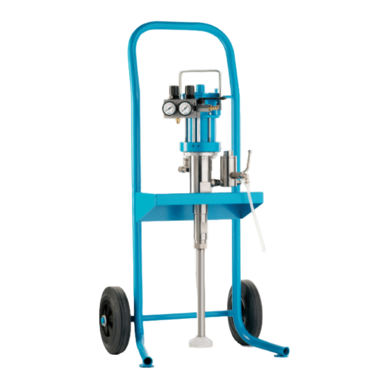
Unit Description 3.2.1 PROFIT series No. Description Dual air regulator (see chap. 3.3) Pressure gauge for displaying the air inlet pressure and the atomizer air pressure Air motor Material pump Cart Carrying handle Compressed air shut-off valve Compressed air connection High pressure filter (for more information see Chapter 6.5 High pressure filter on page 41) -
Page 22: Phoenix Series
Unit Description 3.2.2 PHOENIX series No. Description Dual air pressure regulator (see chap. 3.3) Cart Material pump Muffler Air motor Overflow High pressure filter Drain valve for pressure release Material hose connection Material inlet/suction Fig. 13 Phoenix - Airless on cart Design variants: min. -
Page 23: Dual Air Regulator
Unit Description 3.3 Dual air regulator In addition to the air regulator for the air inlet pressure of the pump, AirCombi devices are also equipped with an additional air regulator for regulating the atomizer air pressure. The models 11032 from the Phoenix series are equipped with a complete maintenance unit instead of the dual air pressure regulator (see chapter 3.4). -
Page 24: Air Maintenance Unit
Unit Description 3.4 Air maintenance unit The air maintenance unit prevents condensate and dirt particles from en- tering the machine and supplies the compressed air with pneumatic oil for lubricating moving parts. The maintenance unit is only used for the models 11032 from the Phoenix series. -
Page 25: Optional Expansion Parts And Accessories
The following section lists only some of the most common accessories and expansion parts. The detailed accessory catalogue can be found at www.wiwa.de. More infor- mation and order numbers can also be obtained from an authorized WIWA dealer or the WIWA service department. 3.5.1 AirCombi spray gun The AirCombi spray gun is not part of the stand- ard scope of delivery. -
Page 26: Transport, Installation And Assembly
Transport, installation and assembly 4 Transport, installation and assembly The unit left the factory in flawless condition and was appropriately packed for transportation. Check the unit for any damage in transit and for completeness on receipt. 4.1 Transportation Please follow these notes when transporting the unit: Ensure sufficient load bearing capacity of lifting gear and lifting tackle ➤ when loading the unit. The dimensions and weight of the unit can be found on the unit card or on the type plate. -
Page 27: Assembly
Transport, installation and assembly Safety measures at the place of installation: This unit requires a solid base and sufficient free space for safe ➤ operation. Always keep the working area, especially all walkways and standing ➤ areas, clean and tidy. Immediately remove any spilled material and cleaning agent. Always ensure adequate ventilation at the work place to avoid damage ➤... -
Page 28: Mounting The Wall Bracket (Optional)
It must be greater than or equal to the maximum operating pressure of the unit as specified on the type plate. Only use conductive material hoses. All original material hoses from WIWA are conductive and perfectly adapted to our equipment. Connect the atomizer air hose (blue): •... -
Page 29: Grounding The Unit
Transport, installation and assembly Fig. 21 Mounting spray hose and atomizer air hose No. Designation Connection for the spray hose (1/4 NPSM) Connection for atomizer air hose (G 1/4) Observe the operation manual for the spray gun. 4.3.3 Grounding the unit WARNING The high flow velocities associated with the Airless spraying method may ... - Page 30 Transport, installation and assembly Ensure that • the compressed air shut-off valve is closed, • the air regulator has been turned down fully. Connect the air hose to the air inlet of the pressure regulator (see Fig. 22) or to the maintenance unit (see Fig. 23), depending on the version. Fig.
-
Page 31: Operation
Operation 5 Operation The unit must have been set up correctly and completely assembled. ➤ Do not start commissioning the unit unless you have the specified pro- ➤ tective equipment. For details, refer to chapter 2.5.4 on page 16. A sufficient quantity of the spraying material has to be available. ➤ Observe the information from the respective material manufacturer. You will need: ➤... -
Page 32: Spraying
Operation 5.2 Spraying The following steps for commissioning have to be completed before spraying (see Chapter 5.1 Commissioning the unit on page 31). Place the suction pipe into the spraying material. Regulate the air inlet pressure so low that the pump runs slowly. Unlock the spray gun and operate it until clean spraying material runs out. -
Page 33: Hints For Achieving Good Coating Results
Operation Start with low atomizer air pres- no air right! ➤ enough air sure and increase it gradually until all plumes are atomized and incorporated into the spray pattern with the flat spray control fully open (round spray control CLOSED). The atomizer pressure should be in the range of approx. 1.5 - 4.5 bar (depending on material Increasing the atomizer air pressure viscosity). -
Page 34: Flushing
Operation 5.3 Flushing Flushing the unit is necessary: At initial and re-commissioning ➤ the unit has to be flushed with a cleaning agent to ensure that the spray- ing material is not negatively affected by the test medium that was used at the factory to test correct functioning. When changing materials ➤ For terminating work and at decommissioning ➤... -
Page 35: Material Change
Operation Regulate the air inlet pressure low enough so that the pump runs slowly. Open the drain valve on the high pressure filter until pure cleaning agent is emitted, directing the hose into a collecting vessel. Close the drain valve. Hold the spray gun laterally against the inner wall of the collecting ves- sel. -
Page 36: Interruptions To Work
Operation 5.6 Interruptions to work Always secure the spray gun, even for shortest work breaks. Secure the spray gun for short work breaks. Take note of the potlife of the materials used, particularly when using multi-component materials. The system has to be flushed and cleaned completely with the stipulated cleaning agent within the potlife indicated by the manufacturer. Please note: Curing time is reduced at higher temperatures. -
Page 37: Maintenance
Maintenance and repair work on electrical components must only be ➤ carried out by trained electricians – any other maintenance and repair work must be performed by WIWA customer service or by specially trained personnel. WARNING Sources of ignition may result from maintenance work (e.g. through mechanical sparks, electrostatic charge, etc.). -
Page 38: Regular Inspections
Maintenance 6.1 Regular inspections The unit has to be examined and serviced by an expert regularly: before initial commissioning, ➤ after the modification or repair of parts of the system, which could affect ➤ safety, after work breaks longer than 6 months, ➤ but at least every 12 months. ➤ For decommissioned units, the inspection can be postponed until the next commissioning. -
Page 39: Maintenance Unit
Maintenance 6.3 Maintenance unit Devices without a maintenance unit are equipped with a dual air pressure regulator (see Fig. 14 on page 23) which requires no maintenance. The maintenance unit is equipped with the following maintenance elements: Fig. 29 Maintenance elements (same on all maintenance units) No. -
Page 40: Checking And Adjusting The Fog Oiler
Top up lubricant, if necessary. We recommend using pneumatic oil (order number 0632579) or anti- freeze (order number 0631387) from WIWA. Reattach the oil reservoir to the air maintenance unit. 6.3.2 Checking and adjusting the fog oiler Let the unit run slowly under load. -
Page 41: High Pressure Filter
Fig. 31 Filling in (1) and draining (2) re- lease agent for PHOENIX CAUTION The pump packing may only be replaced by trained personnel or by the WIWA service. After the examination, top up the amount of fresh release agent through the filler opening (1). We recommend using release agent from WIWA (order number 0163333). - Page 42 Maintenance Fig. 33 Removing the filter element for high pressure filter Fig. 32 Removing the filter element for high pressure filter type 05 type 01 Designation 1 a Drain screw b Discharge ball valve Supplied tools a Open-end wrench b Pin spanner Filter element Threaded bolt O-ring Fig. 34 Removing the filter element for high pressure filter type 11 Open the drain screw (1a) or the drain shut-off valve (1b) to ensure that the unit is fully depressurized.
-
Page 43: Cleaning The Filter Element
Check the O-ring (7) – replace if damaged. Screw the cap (3) on the high pressure filter and tighten it with the pin spanner (2b) or the open-end wrench (2a). 6.5.3 Filter elements for high pressure filters Insert the filter element suitable for the spraying material and the spraying nozzle into the high pressure filter. The mesh size should always be slightly finer than the bore of the nozzle used. Filter element Nozzle size WIWA art. no. High pressure High pressure filter filter type 11 type 01 + type 05 M 200 (white) up to 0.23 0162744 0160636 mm/.009”... -
Page 44: Recommended Operating Materials
Maintenance 6.6 Recommended operating materials Only user original operating materials from WIWA: Operating materials WIWA order number Release agent, yellow (0.5 l) ¹ 0163333 (standard) Release agent, red (0.5 l) ¹ 0640651 (e.g. for isocyanate) Pneumatic oil (0.5 l) ² for fog oiler 0632579 ¹ ... -
Page 45: Rectification Of Faults
Rectification of faults 7 Rectification of faults Fault Possible cause Remedy – Compressed air shut-off valve – Open the compressed air shut-off The pump does not start, despite closed. valve. operation of spray gun (without nozzle) or opened relieve valve on – High pressure filter clogged. – Clean or renew the filter element. - Page 46 Rectification of faults Fault Possible cause Remedy – Packing worn. – Replace the packing. Material escapes from the overflow Note: Do not close off the over- on the air motor. flow! – Water in the atomizer air hose – Retrofit water separator on the Fluctuations in the spray jet compressor –...
-
Page 47: Technical Data
Technical data 8 Technical data 8.1 PROFIT series Model 3010 3022 3033 4210 4222 4233 Max. free-flow output (l/min) Pressure ratio 10 : 1 22 : 1 33 : 1 10 : 1 22 : 1 33 : 1 Pump capacity per double stroke (cm ³... -
Page 48: Unit Card
Technical data 8.3 Unit card The unit card contains all important and safety relevant data and information about the unit. Exact designation and manufacturer data, ➤ Technical data and limit values, ➤ Equipment and test certificate, ➤ Purchasing data, ➤ Unit identification (machine components and supplied accessories with ➤ item numbers and spare part numbers). 8.4 Type plate The type plate is located on the cylinder of the material pump. - Page 49 Translation of the original operation manual AIRCOMBI AirCombi_BAoDB_en_1405 • jw...
- Page 50 WIWA Service +49 (0)6441 609 140 Hauptsitz und Produktion WIWA Außendienst weltweit WIWA Wilhelm Wagner GmbH & Co. KG Robert Jansen Gewerbestr. 1 - 3 Senior-Verkaufsleiter 35633 Lahnau, Deutschland Finnland, Schweden, Norwegen, Dänemark, Großbritannien, Südir- land, Holland, Belgien, Frankreich, Spanien, Portugal, Italien, Kroatien, Tel.: +49 (0)6441 609-0...
Need help?
Do you have a question about the AIRCOMBI ProFit Series and is the answer not in the manual?
Questions and answers