Table of Contents
Advertisement
Quick Links
Contents
Translation of the original operating instructions
DM270_BAoDB_en_1507 • rs
1 Foreword........................................................................................................6
2 Safety .............................................................................................................7
2.1 Explanation of symbols ................................................................................7
2.2 Safety information ........................................................................................9
2.2.1 Operating pressure ............................................................................9
2.2.2 Risks due to the spray jet ..................................................................9
2.2.3 Risks due to electrostatic charging ..................................................10
2.2.4 Risks due to hot or cold surfaces .....................................................10
2.2.5 Explosion protection ........................................................................ 11
2.2.6 Health risks ...................................................................................... 11
2.3 Information signs on the machine ..............................................................12
2.4 Safety equipment .......................................................................................12
2.4.1 Safety valves ...................................................................................13
2.4.2 Compressed air shut-off valve .........................................................14
2.4.3 Ground cables .................................................................................14
2.5 Operating and maintenance personnel ......................................................15
2.5.1 Obligations of the machine owner ...................................................15
2.5.2 Personnel qualifications ...................................................................15
2.5.3 Authorised operator .........................................................................15
2.5.4 Personal protective equipment ........................................................15
2.6 Guarantee information ...............................................................................16
2.6.1 Conversions and alterations ............................................................16
2.6.2 Spare parts ......................................................................................16
2.6.3 Accessories ......................................................................................16
2.7 Behaviour in an emergency .......................................................................17
2.7.1 Bring the machine to a standstill and relieve the pressure ..............17
2.7.2 Leaks ...............................................................................................17
2.7.3 Injuries .............................................................................................17
3 Machine description ...................................................................................18
3.1 Intended use ..............................................................................................18
3.2 Erroneous use............................................................................................18
3.3 Machine configuration ................................................................................19
3.4 Compressed air regulation unit ..................................................................21
3.5 Pressure and metering monitoring .............................................................21
3.6 Temperature displays .................................................................................22
3.7 Proportioning pump....................................................................................22
3.8 Mixing unit ..................................................................................................23
3.9 Flushing pump ...........................................................................................24
DUOMIX
270
Contents
3
Advertisement
Table of Contents

Related Manuals for wiwa DUOMIX 270


Summary of Contents for wiwa DUOMIX 270
-
Page 1: Table Of Contents
Contents Contents 1 Foreword......................6 2 Safety ......................7 2.1 Explanation of symbols ................7 2.2 Safety information ..................9 2.2.1 Operating pressure ................9 2.2.2 Risks due to the spray jet ..............9 2.2.3 Risks due to electrostatic charging ..........10 2.2.4 Risks due to hot or cold surfaces .............10 2.2.5 Explosion protection ................ - Page 2 Contents 3.10 Optional expansions and accessories .............25 3.10.1 Fluid heaters ..................25 3.10.2 Agitators ..................25 4 Transport, installation and assembly............26 4.1 Transport ....................26 4.2 Installation site ...................26 4.3 Assembly....................28 4.3.1 Connect the spray hose and spray gun ...........28 4.3.2 Ground the machine ................28 4.3.3 Insert filter inserts in the high pressure filter ........29 4.3.4 Connect compressed air supply ............29 5 Operation .....................30...
- Page 3 Contents 6.6 Recommended operating materials ............42 6.7 Special tools....................42 7 Troubleshooting ..................43 8 Technical data .....................44 8.1 Machine card .....................44 8.2 Type plates ....................44 Translation of the original operating instructions DUOMIX DM270_BAoDB_en_1507 • rs...
-
Page 4: Foreword
WIWA Wilhelm Wagner GmbH & Co. KG Gewerbestr. 1-3 • 35633 Lahnau • Germany Tel.: +49 6441 609-0 • Fax.: +49 6441 609-50 • Email: info@wiwa.de • Website: www.wiwa.de These operating instructions are intended exclusively for the preparation, operating and maintenance personnel. -
Page 5: Safety
Safety information warns of potential accident risks and describes the measures required for accident prevention. In the operating instructions from WIWA, safety information is highlighted and labelled as follows: DANGER Signals a risk of accidents that are very likely to result in serious injuries and... - Page 6 Safety Risk of explosion due to explosive substances Risk of accident due to electricity or electrostatic charge Risk of crushing due to moving machine parts Risk of burning due to hot surfaces Risk of freezing due to cold surfaces The first line of the safety instructions indicates the personal protective equipment that must be worn.
-
Page 7: Safety Information
Safety 2.2 Safety information Always remember that the machine operates in a high pressure process and can cause life-endangering injuries if handled incorrectly! Always observe and follow all information in these operating instructions and in the separate operating instructions for the individual machine parts or the optionally available auxiliary devices. -
Page 8: Risks Due To Electrostatic Charging
Always ensure contact between the spray gun and the container wall. ➤ Only use electrically conductive material hoses. ➤ All original material hoses from WIWA are conductive and designed for our machines. WARNING If the machine becomes contaminated with material during operation, an electrostatic charge may be generated with the increasing coating thickness. -
Page 9: Explosion Protection
Safety 2.2.5 Explosion protection WARNING Machines that are not explosion-protected must not be used in operating facilities that fall under the explosion protection ordinance! Explosion-protected machines can be identified by the corresponding mark on the type plate and/or the ATEX declaration of conformity provided . Explosion-protected machines fulfil the requirements of directive 94/9/EC for the device group, device category and temperature class cited on the type plate or in the declaration of conformity. -
Page 10: Information Signs On The Machine
(see Fig. 1), For your safety • Pour votre sécurité Por razones de seguridad • Для вашей безопасности Güvenliğiniz için • Dla Twojego bezpieczeństwa www.wiwa.de indicate possible hazard points and must För din säkerhet • Para a sua segurança www.wiwa.com be observed. -
Page 11: Safety Valves
Changing the mixing ratio changes the pressure transmission and therefore also the maximum permissible air intake pressure. In this case the existing safety valve must be replaced following agreement with WIWA. Translation of the original operating instructions DUOMIX DM270_BAoDB_en_1507 • rs... -
Page 12: Compressed Air Shut-Off Valve
Safety 2.4.2 Compressed air shut-off valve The compressed air shut-off valve on the maintenance unit interrupts the air closed supply to the entire machine. The machine will stop immediately. The functional principle: Open Position ball valve in the ➤ open flow direction Close ... -
Page 13: Operating And Maintenance Personnel
Safety 2.5 Operating and maintenance personnel 2.5.1 Obligations of the machine owner The machine owner: is responsible for training the operating and maintenance personnel, ➤ must instruct the operating and maintenance personnel on correct handling ➤ of the machine, and on wearing the correct work clothing and protective equipment, must make work aids (such as lifting gear for transporting the machine or ➤... -
Page 14: Guarantee Information
When repairing and maintaining the machine, only use original spare parts ➤ from WIWA. If spare parts are used, that have not been produced or supplied by WIWA ➤ then the guarantee is voided and all liability shall be excluded. -
Page 15: Behaviour In An Emergency
Safety It is essential to observe the safety provisions applicable to the accessories. ➤ You can find these safety provisions in the separate operating instructions for the accessories. 2.7 Behaviour in an emergency 2.7.1 Bring the machine to a standstill and relieve the pressure In an emergency you must bring the machine to a standstill immediately and relieve the pressure. -
Page 16: Machine Description
Machine description 3 Machine description DUOMIX has been designed according to your specific requirements (process material, mixing ratio, output, etc.). The process material is fed directly to the proportioning pump or via feed sys- tems. The proportioning pump transports both components – correctly metered –... -
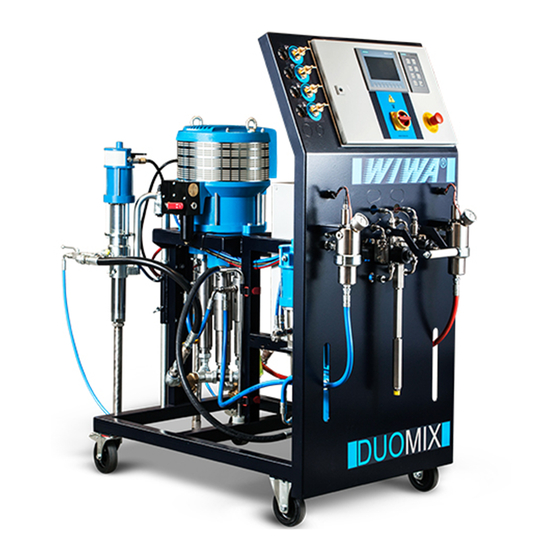
Page 17: Machine Configuration
Machine description 3.3 Machine configuration Fig. 5: Front view of the DUOMIX No. Designation Compressed air regulation unit Control cabinet for the pressure and metering monitoring Main switch Contact manometer for the pressure and metering monitoring Temperature displays for the A and B component Pressure gauge for the material pressure of the A-component High pressure filter for the A component Mixing unit... - Page 18 Machine description Fig. 6: Rear view of the DUOMIX No. Designation Proportioning pump Agitator Feed tank for the B component Feed tank for the A component Frame Control box for electrical connections of the fluid heaters Flushing pump Fluid heater for the B component Fluid heater for the A component Translation of the original operating instructions DUOMIX...
-
Page 19: Compressed Air Regulation Unit
Machine description 3.4 Compressed air regulation unit By default, the air regulators and pressure gauges for the air inlet pressure of the pro- portioning pump and the flushing pump are installed in the compressed air regulation unit (see Fig. 7). Depending on the configu- ration of the machine, further air regulators and pressure gauges can be added for optional extensions and accessories. -
Page 20: Temperature Displays
Machine description No. Designation and function With the selector switch “Manual/Automatic” you decide whether both operation limits should be monitored (= “Automatic”), or only the upper one (= “Manual”). For start-up, set the selector switch to “Manual”. For spray operation, set the selector switch to “Automatic”. The contact pressure gauge monitors the pressure of the B-component (hardener) and switches the machine off when the operation limits are reached. -
Page 21: Mixing Unit
Machine description 3.8 Mixing unit The two components of the process material are only combined once in the mixing unit. Actual mixing takes place in the static mixer, which is mounted at the material outlet of the mixing unit. From here the material travels via the spray hose to the spray gun. -
Page 22: Flushing Pump
Machine description Operating mode Flush B Flush A+B Stop Open and close the flushing levers multiple times in alternation during flush- ing, in order to ensure that each component is flushed through separately. Finally, flush with both levers in the flushing position. 3.9 Flushing pump In flushing mode the flushing pump con- veys the flushing agent from the flushing... -
Page 23: Optional Expansions And Accessories
The following list contains just some of the most common accessories and expansions. You can find the detailed accessory catalogue at www.wiwa.de. For further information and order numbers, you can also contact an approved WIWA dealer or WIWA customer service. -
Page 24: Transport, Installation And Assembly
Transport, installation and assembly 4 Transport, installation and assembly The machine left the factory in faultless condition, packaged correctly for trans- port. Check the machine at the time of receipt for any transport damage and for completeness. 4.1 Transport In case of machine transport observe the following information: When loading the machine ensure sufficient load-bearing capacity of the ➤... - Page 25 Transport, installation and assembly WARNING If the machine is used outdoors during a storm, a life-endangering situation may arise for the operating personnel in the event of lightening! Never operate a machine outdoors in a storm! ➤ The machine owner must ensure that the machine is equipped with suit- ➤...
-
Page 26: Assembly
Transport, installation and assembly 4.3 Assembly WARNING If untrained personnel carry out assembly work, they endanger themselves and others, as well as risking the operational safety of the machine. Electrical and electronic parts must be installed exclusively by specialist ➤ personnel with an electrical qualification –... -
Page 27: Insert Filter Inserts In The High Pressure Filter
Transport, installation and assembly 4.3.3 Insert filter inserts in the high pressure filter Insert a filter insert in the high pressure filter that is appropriate for the process material. Further information on this can be found in Chap. 6.5.2 on page 41. 4.3.4 Connect compressed air supply CAUTION Auf Laufflächen verlegte Leitungen sind eine Stolper- und damit Verletzungs-... -
Page 28: Operation
Operation 5 Operation Prerequisites: The machine must be correctly erected and fully assembled. ➤ Only put the machine into operation if you are equipped with the prescribed ➤ personal protective equipment. Details on this can be found in Chap. 2.5.4 on page 15. -
Page 29: Put The Flushing Pump Into Operation
Operation 5.1.2 Put the flushing pump into operation The flushing pump must always be ready for operation during work, in order that all parts that have come into contact with the mixed material can be flushed at any time within the specified pot life! Place the suction intake for the flushing pump in the flushing media tank. -
Page 30: Coating
Operation 5.2 Coating Before coating, the unit must be taken into service. Set the levers at the mixing unit to „Spray“. Regulate the air pressure regulator of the proportioning pump to a low air inlet pressure. Keep spraying the flushing agent residues in the unit into a collecting ves- sel, until material to be processed starts flowing out. -
Page 31: Tips For Good Coatings
Operation After each change in the spray pressure it is necessary to reset the pressure and metering monitoring. If the pointer of the contact manometer does not move or only moves insufficiently, the system must not be put into operation due to the risk of erroneous mixing! 5.2.3 Tips for good coatings Hold the spray gun at a right angle (90°) to the... -
Page 32: Pressure Relief
Operation 5.4 Pressure relief Close the compressed air shut-off valve on the maintenance unit. Set the levers at the mixing unit to "Circulation". Trigger the spray gun, until the material pressure has been fully relieved. WARNING If parts of the equipment (e.g. spray nozzle, material filter on the spray gun, material hose, high pressure filter, suction strainer, etc.) are clogged the pressure cannot be fully released. -
Page 33: Material Change
The machine has been specially configured for your application case. It is necessary to check compatibility of the materials used with other materials in each individual case. WIWA shall be happy to assist you in determining the suitability of your machine for other materials. -
Page 34: Storage
Operation 5.8 Storage Store the machine at a location at which it is protected from dirt, damp, frost and heat. Storage temperature Minimum of Maximum of 0 °C 32 °F 40 °C 104 °F 5.9 Disposal It is necessary to collect residues of spray material, cleaning fluids, oil, greases and other chemical substances according to the legal regulations for recycling or disposal. -
Page 35: Maintenance
Maintenance and repair work on electrical parts must be carried out by ➤ specialist personnel with an electrical qualification – all other mainte- nance and repair work must be carried out by WIWA customer service or specially trained personnel. WARNING During maintenance work ignition sources may arise (e.g. -
Page 36: Regular Testing
Maintenance 6.1 Regular testing The machine must be tested and maintained regularly by a specialist: prior to first commissioning, ➤ after changes to / the servicing of parts of the installation that affect safety, ➤ after an interruption to operation lasting more than 6 months, ➤... -
Page 37: Maintenance Unit
Maintenance 6.3 Maintenance unit The maintenance unit prevents con- densation water and dirt particles from entering the equipment. The maintenance unit is equipped with the following maintenance elements: No. Designation Compressed air shut-off valve with automatic venting function / EMERGENCY STOP Compressed air connection Air outlet for automatic venting Slide for opening the water... -
Page 38: Proportioning Pump
Maintenance 6.4 Proportioning pump In order to avoid damaging the proportioning pump due to material hardening, the release agent chambers of the fluid pumps are filled with release agent as a material plasticiser. Depending on the characteristics of the process materi- al, signs of wear will appear on the fluid pump packings after a certain time in operation. -
Page 39: High Pressure Filters
The mesh size should always be slightly finer than the bore of the nozzle used. Filter element Nozzle size WIWA order no. M 200 (white) up to 0,23 mm/.009“ 0659107-200 M 150 (red) > 0,23 mm/.009“... -
Page 40: Recommended Operating Materials
6.6 Recommended operating materials Only use original operating materials from WIWA: Operating materials WIWA order number Release agent (0,5 l) ¹... -
Page 41: Troubleshooting
Return hose or return ball valve Clean return hose and return ball valve, clogged replace if required. Repair air motor – if necessary call the WIWA Air motor defective customer service for assistance The proportioning pump is run- Suction strainer clogged... -
Page 42: Technical Data
D-35633 Lahnau www.wiwa.de Gewerbestraße 1-3 the device type and the serial num- Druckluftbetriebene Kolbenpumpe/Air operated piston pump Geräte-Type/Unit Fleximix 2 Duomix 270 ber, as well as the machine's year of Geräte-Type/Unit Misch.Verhältnis/MixingRatio 0,5:1 - 17:1 FM p. DH/Output p. cycle cm³... - Page 43 Technical data Furthermore, some machine components have a separate type plate, such as: the air motor for the proportioning pump ➤ the material pumps for the A and B component ➤ the flushing pump ➤ the control cabinet, etc. ➤ These type plates contain the technical data and serial numbers for the corre- sponding machine components.
- Page 44 WIWA Service +49 (0)6441 609 140 Headquarters and production WIWA Wilhelm Wagner GmbH & Co. KG Gewerbestr. 1 - 3 35633 Lahnau, Germany Phone: +49 6441 609-0 Fax: +49 6441 609-50 E-Mail: info@wiwa.de Homepage: www.wiwa.de WIWA Partnership USA WIWA LP 107 N.
Need help?
Do you have a question about the DUOMIX 270 and is the answer not in the manual?
Questions and answers