Table of Contents
Troubleshooting

Subscribe to Our Youtube Channel
Related Manuals for wiwa DUOMIX PU280


Summary of Contents for wiwa DUOMIX PU280
- Page 1 Operation manual WIWA 2K-DUOMIX PU 280 Type: ❍ 280 ❍ 280+ Version: ❍ 400V ❍ 230V Variants with: ❍ Feed pumps Serial-No. _ _ _ _ _ _ _ _ Translation of the original operation manual 1307_PU280_SV1018DV1020_DB_en • ski...
- Page 2 PU 280 herewith declares that the equipment types PU 280+ with Serial-No.: are in conformance with the provisions of the above-mentioned directive. Documentary authority: WIWA GmbH / Phone: +49 6441 609 0 Lahnau, 10.07.2013 Place, Date Heidrun Wagner-Turczak Managing Director Copyright ©...
-
Page 3: Table Of Contents
Table of Contents Foreword Important for your safety 1.2 Machine card 1.3 Pictogrammes 1.4 Notices on the machine Safety Information 2.1 Danger sources 2.1.1 Dangers caused by the spray jet 2.1.2 Danger to health 2.1.3 Danger for equipment 2.1.4 Danger caused by electric voltage 2.1.5 Danger caused by explosion 2.1.6 Danger caused by disregarding the explosion protection 2.2 Operating personnel 2.2.1 Setup, cleaning, maintenance and repair work 2.2.2 Protective equipment 2.3 Safety features 2.4 Handling the system and auxiliary materials 2.5 Emergency procedures 2.5.1... - Page 4 3.11 Control cabinet 3.11.1 Components on the control cabinet 3.11.2 System control 3.12 Menu 3.12.1 Welcome screen = ACTUAL temperature 3.12.2 NOMINAL temperature 3.12.3 Alarm 3.12.4 Parking 3.12.5 Software version Installation and Assembly 4.1 Setting up the unit 4.2 Assembling attachments and accessories 4.2.1 Connection of the hose package 4.2.2 Connecting individual hose package segments 4.2.3 Connection spray gun to the hose package 4.2.4 Connection feed pumps 4.3 Ground the system 4.4 Check the condition of the release agent 4.5 Electric connection 4.6 Compressed air connection Commissioning Operation...
- Page 5 Maintenance 10-1 10.1 Check cycles 10-1 10.2 Important notes 10-1 10.3 Maintenance unit 10-2 10.4 Draining the condensation water 10-2 10.5 Notes on oil reservoir and water separator 10-2 10.6 Separators 10-3 11.1 Circulation 11-1 11.1.1 Circulation circuit 11-1 Optional equipment 11-1 11.1.2 Circulation / ventilation 11-2 11.2 Silicagel filter 11-3 11.3 Spray gun 11-5 11.3.1 Spray gun components 11-5 11.3.2 Safety features 11-6...
-
Page 6: Foreword
Foreword Important for Operating personnel should always have access to this user manual! The owner of the unit must ensure that the operator of the unit always has an your safety operating manual at his/her disposal in a language he/she understands! All persons involved in the set-up, commissioning, operation, maintenance, repair and servicing of the machine must have read and understood the user manual beforehand, and the chapter on Safety in particular. We recommend to the owner of this unit to have this confirmed in writing. In principle you should refrain from any work method that would affect the safety products and the operating personnel. Please read and comply with: the applicable guidelines for your country. ➤ In Germany, these are the “Richtlinien für Flüssigkeitsstrahler” (Guidelines for Liquid Jets), issued by: the Hauptverband der Gewerblichen Berufsgenossenschaften. the manufacturer's instructions and processing guidelines for coating or trans- ➤ fer materials are to be respected at all times. This machine has been designed and manufactured under due consideration of all safety-related aspects. It corresponds to the current standard of technology and to applicable accident prevention regulations. The machine left the factory in perfect condition and guarantees a high level of technical reliability and safety. Nevertheless, there are certain risks that can arise from incorrect operation or misuse: to life and limb of the operator or third party, ➤ to the machine and other material assets of the owner, ➤ to efficient work with the machine. ➤ Machine card This user manual is only valid in combination with the following machine card. The machine card contains all important and safety relevant data and informa- tion about the machine. exact designation and manufacturer data ➤... -
Page 7: Pictogrammes
Foreword The notices and symbols used in this manual have the following meanings: Pictogrammes NOTICE Indicates an informative text passage. You should pay particular attention when reading it. WARNING A potentially dangerous situation is indicated. Non-observance can lead to death or very serious injury. DANGER OF EXPLOSION Indicates a situation with potential danger of explosion. Strict compliance with these notes is mandatory. VOLTAGE A situation showing danger of explosion by electrostatic charge is indicated. Strict compliance with these notes is mandatory. HOT SURFACES Identifies a situation involving the danger of burning on a hot surface. Do not touch hot surfaces without wearing gloves. The following symbols indicate that protective equipment should be worn. With your health in mind you should always comply with the recommendations of the material manufacturer. WEAR PROTECTIVE CLOTHES USE RESPIRATORY PROTECTION USE EYE PROTECTION WEAR PROTECTIVE GLOVES WEAR HEARING PROTECTION... -
Page 8: Notices On The Machine
Foreword Appropriate information signs and symbols on the machine refer to possible dan- Notices on ger areas and must be respected at all costs. the machine Information signs and symbols must not be removed from the machine. Damaged and illegible information signs and symbols must be replaced immedi- ately. The following signs can be found on the machine: Type plate on plant control cabinet, (Figure 1.1). ➤ Please check that the type plate data are identical with those on the machine card. In case of discrepancies or if the type plate is missing please notify us im- mediately. Figure 1.1 Type plate on plant control cabinet, (Figure 1.2). ➤... -
Page 9: Safety Information
Safety Information Please remember that dual component systems work with extremely high pres- Danger sures and may cause life threatening injuries if used inappropriately. sources Always pay attention to and follow all notes in the user manuals for the optionally offered accessory equipment. Pay particular attention to the chapter on safety notes for the corresponding components. 2.1.1 Dangers caused Please comply with the following instructions: by the spray jet Never point the spray gun at yourself, other persons or other living beings! ➤ Never hold your fingers or hand in front of the spray gun and never reach into ➤ the jet spray. Material hoses must be able to withstand pressures beyond the maximum ➤ working pressure. Material hoses must never be repaired! ➤ Never try to seal leakages on connections and high pressure hoses by hand ➤ or by wrapping fabric around them. In case of leakages immediately depres- surize the entire system (spray gun, hose, pump, etc.). Defective parts must be replaced. Secure the spray gun(s) each time work is interrupted, even for short breaks, ➤ and check that it is properly secured, (Figure 2.1). Switch off the machine before starting maintenance and cleaning work on the ➤... -
Page 10: Danger To Health
Safety Information 2.1.2 Danger to health In closed rooms or with pressurized systems, in which aluminium components ➤ or galvanized parts have contact with the solvent, hazardous chemical reac- tions may occur when using 1.1.1 - trichloroethane (TCE), methylene chloride or other solvents containing chlorinated hydrocarbons (CFCs). If you wish to use the aforementioned solvents or varnishes and paints containing such solvents, we advise you to consult the - customer service or directly. We would like to point out that we have a series of dual component sys- ➤ tems in rust and acid proof design available for such materials. DANGER OF BURNING! ➤ Depending on the set temperature, the outer surface of the adapter can heat up considerably. You should therefore always wear protective gloves when having to work on the adapter! 2.1.3 Danger for Changing the mixing ratio may cause a change in pressure ratio and thus ➤ equipment require the adaptation of the max. permissible air inlet pressure. In this case the existing safety valve must be replaced. Consultation with is highly recommended. The system should never be operated without safety valve! ➤ If the safety valve needs to be replaced, you can find the corresponding order number on the machine card. The maximum operating pressure specified by us must generally be adhered ➤... -
Page 11: Danger Caused By Explosion
Safety Information 2.1.5 Danger caused Never spray cleaning agent or cleaning agent containing materials into cone- ➤ top cans or drums with bunghole! by explosion Always use open containers. Stand the containers on a grounded surface. ➤ When using metal containers avoid contact between spray gun and container wall, because of possible electrostatic charging. The high flow velocities associated with the Airless spraying method may cause static charging. Static discharges can cause fire and explosion. The original DUOMIX PU 280 is earthed via the electrical connection as standard. Never operate the unit outside in case of a thunderstorm. ➤ Because of the generated electrostatic charging you should only use conduc- ➤ tive material hoses. All original material hoses are conductive and per- fectly matched to our equipment. The maximum permitted working pressures of the hoses must be higher than or equal the maximum operating pressure of the corresponding dual component system. Switch off all heaters when working with cleaning agents in the material circuit ➤ (e.g. complete cleaning). Complete cleaning must only be performed after the system has cooled down. 2.1.6 Danger caused The system must NOT be operated in explosion protection zones! ➤... -
Page 12: Protective Equipment
Safety Information 2.2.2 Protective We would like to point out that the valid guidelines and stipulations depending ➤ on the work environment (mining, closed rooms, etc.) must be respected in equipment any case. Always wear the protective clothes specified by the material manufacturer to ➤ avoid injuries. It is recommended that the operator should always wear a respiratory protec- ➤ tion mask, even though the paint mist has been minimized in Airless spray painting applications with correct pressure setting and working mode. Wear protective goggles to protect against eye injuries caused by mechanical ➤ or chemical influences. Wear protective gloves with lower arm protection to avoid burn injuries. ➤ The sound pressure level of this unit is less than 85 db(A). ➤ However, operating personnel should still be provided with suitable noise protection equipment. Safety All units are delivered with the following safety features: features Master switch, (Figure 2.3) When the master switch on the control cabinet is switched to position “0 / OFF” 0 / OFF I / ON both the electric power and compressed air supplied are immediately cut off. Note: The compressed air supply to the spray is not interrupted! ➤ Figure 2.3 Material may still be under pressure in the system! ➤... -
Page 13: Handling The System And Auxiliary Materials
Safety Information All safety features must be checked: before each start-up of the equipment! ➤ before starting work on or with the equipment! ➤ after completion of setup work! ➤ Attention! after cleaning and servicing work! ➤ after maintenance and repair work! If any of the safety fea- ➤ tures is not fully functional or any other fault is found on the machine, the Check list to check the safety features on the depressurized unit system must be shut down Please check: ➤ immediately. the lead seal on the safety valve for damage. Operation of the machine ➤ must only be resumed the safety valve for external damage. ➤ after the correct functional the correct function of the master switch. state has been re-estab- ➤ lished. the function of the air pressure valve on the spray gun. ➤ Follow the safety notes and dosing information of the manufacturers and the ➤... -
Page 14: Machine Description
Machine Description Intended DUOMIX PU 280 is most suitable for the application of solvent free use of the dual-component plastic materials (polyurea). This system enables the seamless machine and jointless application of coatings and linings Your dual component system was designed to meet your special requirements (material to be applied, mixing ratio, transfer quantity, etc.). Exact metering of both components is assured by the fixed mixing ratio. The mix- ing ratio can only be changed by exchanging the material pumps. Any other use is deemed to not be in accordance with regulations. The manufacturer's approval must be obtained before units are used for any other purpose or with other materials, i.e. not in accordance with the intended use, otherwise the warranty will become null and void. Intended use also includes compliance with the technical documentation and adherence to the prescribed operating, servicing and maintenance guidelines. Notes on Unauthorized conversions or alterations should not be undertaken on safety warranty grounds. Protective equipment should not be dismantled, converted or bypassed. Use of components which have not been manufactured or delivered by renders any warranty null and void. The unit should only be operated within the prescriptive limit values and machine parameters. Dangers from accessories If original accessories and spares of Wilhelm Wagner GmbH & Co. KG and spares are used, usability with our units is guaranteed. It is, however, mandatory to respect the safety regulations of the accessories and spare parts. These safety regulations are found in the corresponding user manuals for the accessories. -
Page 15: Place Of Installation Of The Machine
Machine Description The systems leave the factory in flawless condition and are appropriately packed Trans- for transport. porting the Upon arrival you should check the unit for any apparent transport damage. ➤ machine and Please contact the WIWA customer service if you detect any damage on the ➤ additional packaging or on the equipment. equipment Disconnect the entire power supply for the machine, even for short transport ➤ distances. Empty the machine before transport. ➤ Do not transport any other objects (e.g. material drums) while lifting or loading ➤ the machine. Remove all loose components (e.g. tools) from the unit. ➤ Caution when loading with hoisting gear! ➤ Ensure sufficient load bearing capacity of lifting gear and lifting tackle ➤ when loading the machine. Never stand under suspended loads or inside the loading area. ➤ This poses a danger to life! You will find the dimensions and weights of the equipment on the machine ➤ card. Secure the load on the transport vehicle against slipping and falling off. ➤ Parts or equipment that have been removed for transport purposes must be ➤... -
Page 16: Storing The Machine And Additional Equipment
Machine Description Store the machine in a frost-free, vibration free, dry and possibly dust free ➤ Storing the environment. machine and The machine and its implements must under no circumstances be stored ➤ additional outside closed rooms. equipment Clean the unit thoroughly of all material residues. ➤ Disposal of Disassemble the entire unit and separate the materials. the machine ➤ and addition- Take metal parts to scrap metal services. ➤ al equipment Plastic parts can be disposed of through the household waste. ➤ Rests of spraying material, cleaning agent, oils, greases and other chemical ➤ substances must be collected in accordance with statutory provisions con- cerning recycling and waste disposal. The official local waste water laws are valid. System with feed pumps for 200 l / 52,80 gal variants drums optionally with: Diaphragm pumps ➤... -
Page 17: System Description
Machine Description System description 3.9.1 Without circulation Poly Poly Figure 3.2 3.9.2 With circulation ... -
Page 18: Material Flow
Machine Description 3.9.3 Material flow (Figure 3.2) + (Figure 3.3) A feed pump must be placed into the delivered drum (200 l bunghole barrels) of each component. Attention! We recommend to equip the drum with the Iso-component (isocyanate) with an additional silicagel filter, to prevent the material from reacting with humidity and Ensure correct component thus crystallization of the material. allocation at all times! red = blue = Both components are fed to the metering pump and exactly metered with the Poly components components respective mixing ratio (see machine card). (isocyanate) (Polyol) Each component is individually heated to the required processing temperature in a material flow heater. The temperature is automatically regulated in accordance with the temperature setting. Preset top temperature limits make sure that the ma- terial will not be overheated. For short breaks the heating may remain switched After the material flow heater, the material arrives: a) for spraying: to the spray gun b) to vent the system: back into the delivered drum (only optional). -
Page 19: System Components
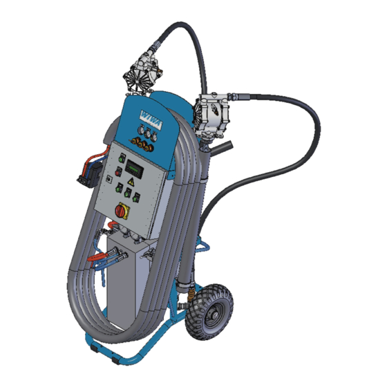
Machine Description 3.10 System components Poly Poly 1.2 1.2 Poly Poly Poly Poly Poly Poly Poly 6.2 Poly + Iso Poly Figure 3.4 Position Description Position Description Metering pump Heated hose package 1.1 Air motor Reverse flow spray gun (see chapter “11.3 Spray gun”, p. 11-5) 1.2 Material pump 6.1 Connection compressed air hose Control cabinet (see chapter “3.11 Control cabinet”, p. -
Page 20: Control Cabinet
Machine Description 3.11 Control cabinet 3.11.1 Components on the control cabinet Figure 3.5 400 V Figure 3.6 230V Position Description Compressed air regulator spray gun Compressed air regulator feed pumps Compressed air regulator metering pump Button “SYSTEM ON” Display Button reset malfunction Heating hose package “ON / OFF” Master switch Material flow heater “ON / OFF”, component Poly Material flow heater “ON / OFF”, component Iso Compressed air pressure gauge spray gun Compressed air pressure gauge feed pumps Compressed air pressure gauge metering pump Original Operation Manual •1307_PU280_SV1018DV1020_BAoDB_en•ski... -
Page 21: System Control
Machine Description 3.11.2 System control This display is used to enter or read the following values: ACTUAL and NOMINAL temperature individually for both material flow heaters ➤ and for the hose package. Display of malfunctions ➤ Button Description forward to the next menu back to the previous menu Numerical value one digit to the left Increase numerical value by one digit Exit settings Confirm settings Figure 3.7 3.12 Menu After switching on the system, the display shows the actual temperature for both 3.12.1 Welcome screen material flow heaters as well as for the hose package. = ACTUAL temperature Hose package Figure 3.8 Before starting work, the nominal temperatures are specified for each component 3.12.2 NOMINAL and for the hose package. temperature Press F1 to call up the corresponding menu. ACTUAL temperature NOMINAL temperature + F4... -
Page 22: Alarm
Machine Description 3.12.3 Alarm Here you will be informed about possible malfunctions: Overpressure ➤ Overtemperature ➤ Sensor break ➤ 1. Line: Overpress Poly Overpress Iso Overtemp Please note also chapter “12.2 Troubleshooting on the spray gun”, p. 12-3 2. Line: Sensorerror Poly Sensorerror Iso Sensorerror Hose Figure 3.11 3.12.4 Parking You should always move the equipment to parking position when interrupting work or at the end of work to prevent the system from being damaged by curing of material. Press F1 to call up the menu. „Parking“. Park position Park status ready => position reaches : 0 => Parking mode deactivated 1 => Parking mode active ... -
Page 23: Installation And Assembly
Installation and Assembly Prerequisites The material to be applied is readily available. ➤ Prepare the material by following the instructions of the material manufacturer. ➤ All materials to be sprayed must be supplied from the manufacturer with data concerning viscosity, application temperatures, mixing ratios, etc. If this is not the case, consult the corresponding manufacturer and ask for these data. For optimal preparation of the spraying materials offers a wide range of accessories, like e.g.: Agitators in various sizes ➤ Material preheating containers ➤ The compressor power must match the air requirements of the equipment, so ➤ that an adequate air supply is ensured, see chapter “13.1 Technical data”, p. 13-1. The diameters of the air supply hoses must match the connections on the ➤ equipment. Setting up Stand the unit on a level and firm base. ➤ the unit Consider the required floor space - see chapter “13.1 Technical data”, p. 13-1. ➤ All operating elements must be easily accessible. -
Page 24: Connection Of The Hose Package
Installation and Assembly 4.2.1 Connection Connect alls hoses and cables to the material flow heater as follows, (Figure ➤ 4.1) - viewed from the front towards the control cabinet. of the hose package Pos. Designation Material hose Material hose Compressed air hose for spray Plug of temperature sensor Plug for hose package heater Figure 4.1 4.2.2 Connecting Connect the individual hose package segments, (Figure 4.2). ➤ The hose package can be made up of several hose package segments of individual 15 m each. The assignment of the individual material hoses can be recognized hose package by the colour coding. segments 3-phase: max. 3 hose package segments ➤... -
Page 25: Connection Feed Pumps
Installation and Assembly 4.2.4 Connection feed Open the bungholes on the material drums. ➤ pumps Insert the feed pumps into the material drums. Ensure horizontal mounting ➤ position and secure hold of pumps. We recommend assembly on a drum lid. Connect the material and compressed air sides of the feed pumps to the ➤ external material containers or fill the material to be applied into the feed fun- Attention! nels. Ensure correct component The Iso material has a tendency to crystallizing when coming into contact allocation at all times! with humidity. We therefore recommend to have the material container for this red = blue = component additionally fitted with an optional - silicagel filter, (see Poly chapter “11.2 Silicagel filter”, p. 11-3. components components Please observe the notes of the material manufacturer. (isocyanate) (Polyol) Guide the return flow hoses (optional) into the corresponding material drums ➤ and secure them against accidental slipping out. Screw fitting return flow on silicagel filter Screw fitting of return flow on drum lid on drum lid of Iso components of Poly components... -
Page 26: Compressed Air Connection
Installation and Assembly Connect the unit to the local compressed air supply. Compressed ➤ air connec- tion Spray Gun Feed Pump Proportioner Pump 0 bar/0 psi 0 bar/0 psi 0 bar/0 psi Compressed air connection on either side Figure 4.4 The machine has been set up for initial start-up. Result Translation of the original Operation Manual •1307_PU280_SV1018DV1020_BAoDB_en•ski... -
Page 27: Commissioning
Commissioning After assembly in the factory the correct functioning of this machine was checked with a testing medium. Attention! All material hoses and the metering pump must first be filled with the material to be applied. Do not switch on any The entire system can first be flushed with the cleaning agent recommended by heater when using clean- the material manufacturer and belonging to the material, before it is filled with the ing agents! material to be applied, to make sure that the spraying material is not contami- nated by the testing medium. Always wear the specified protective clothes. Prerequisites The unit has been set up and connected as specified in chapter “4 Installation and Assembly”, p. 4-1 The following is required (if required) Procedure Prepare the material Open the bungholes on the material drums. ➤ Insert the feed pumps into the material drums. Ensure secure hold of pumps. ➤ Open the shut-off valves for compressed air and material (optional) on each ➤ feed pump. Figure 5.1 Dismantle connection block from spray gun see chapter “11.3.8 Dismantle the spray gun”, p. - Page 28 Commissioning Switch on the equipment Switching the unit on (press the green button) Figure 5.2 Fill the metering pump with material Note! The specified pressures are only guide values and, depending on the viscosity of the material Spray Gun Feed Pump Proportioner Pump or the hose length used, 6 bar/ 87 psi 4 bar/ 58 psi 1 bar/ 14,5 psi may need to be adapted.
- Page 29 Commissioning Pressure tests Check the entire system for leakages. ➤ In case of leakages abort the start-up process and have the malfunction cor- rected by expert personnel. Result The system is ready for operation. You may continue with the normal operation of the system as per chapter “6 Operation”, p. 6-1 or switch off the system as described in chapter “7 Decom- missioning”, p. 7-1 Translation of the original Operation Manual •1307_PU280_SV1018DV1020_BAoDB_en•ski...
-
Page 30: Operation
Operation The following is required Always wear the specified protective clothes. Prerequisites The equipment has been prepared as specified in chapter “5 Commissioning”, ➤ p. 5-1. Checklist: Short description Test state Comment Note! Connection including earthing Always observe and follow Material is available the warnings and data sheets of the material Compressed air connection closed manufacturer. Compressed air supply 0 bar Electrical connection System vented Circulation / relief ... - Page 31 Operation Adjust the compressed air supply Note! The specified pressures are only guide values and, depending on the Spray Gun Feed Pump Proportioner Pump viscosity of the material 0,5 bar/ 7,25 or the hose length used, 6 bar/ 87 psi 6 bar/ 87 psi may need to be adapted. Ensure slow running of the pump . Figure 6.3 Note! Switch on the heating system...
- Page 32 Operation max. pressure difference: Figure 6.6 To relieve the pressure open the valve of the component with the higher pres- ➤ sure. Carefully open only the material valve of the component with too high pressure to allow pressure compensation! Use a collecting vessel for the corresponding component! Figure 6.7 After this pressure compensation close the valve again. ➤ Mounting the spray gun Mount the spray gun to the block. ➤ Follow the notes in chapter “11.3.4 Connect the spray gun to the hose pack- age.”, p. 11-7. Adjust the desired spraying pressure Spray Gun Feed Pump...
-
Page 33: Decommissioning
Decommissioning Switch off the equipment if you want to interrupt work. In case of longer work breaks and / or when changing materials the equipment needs to be shut down. The following is required Always wear the specified protective clothes. General notes To avoid malfunctions of the equipment you should take notice of the following: Never allow the system to run empty. ➤ Do not use any solvents. ➤ 7.1 Activating For short work breaks you may just switch the equipment to parking position. The material temperature can be maintained. parking Activate parking in the display Adjust the park modus in the display. ➤ In this respect follow the notes in chapter „3.12.4 Parking“ of page 3-9. Figure 7.1 Reduce the pressure by carefully pulling the trigger of the spray gun. ➤ The pump switches off when the piston of the material pump has reached bottom position. Close the material valves on the spray gun. ➤ Residual pres- sure approx. 50 bar Switch off the heating (only when required) -
Page 34: Deactivating Parking
Decommissioning Switch off the park modus in the display or switch off the equipment complete- 7.2 Deactivating ➤ ly on the control cabinet. parking In this respect follow the notes in chapter „3.12.4 Parking“ of page 3-9. Figure 7.3 Switch off the equipment completely, if you want to take it out of operation for a Take the longer time. system out of service Perform the work steps as described in chap.chap. “7.1 Activating park- ing”, P. 7-1. Switch the heating off too. On versons with material feed container you must first pump out all material. Shut off the compressed air supply of the metering pump. Spray Gun Feed Pump Proportioner Pump 6 bar/ 87 psi 6 bar/ 87 psi 0 bar/ 0 psi Figure 7.4 Reduce the pressure by carefully pulling the trigger of the spray gun. - Page 35 Decommissioning Regulate the compressed air controllers on the feed pump completely back. The compressed air settings for the spray gun can remain unchanged. Spray Gun Feed Pump Proportioner Pump 6 bar/ 87 psi 0 bar/ 0 psi 0 bar/ 0 psi Figure 7.7 Close the ball valves. Figure 7.8 Switch off the plant. Risk of injury! The system remains pres- surized to avoid crystal- lization of material in the material hoses. Any unintended escape Figure 7.9 of material from the spray...
-
Page 36: Shutting Down The Equipment
Decommissioning Separators Note! The receptacles for the Filling level: feed pumps must always up to 3 cm below be filled with release receptacle agent. Figure 7.10 Shut off the compressed air supply Compressed air connection on either side Figure 7.11 Take the equipment out of service as described in chapter “7.3 Take the Shutting system out of service”, p. 7-2. down the equipment Exchange the material drums against containers with preserving agent. Fill the system with preserving agent. Note! Only use the preserving Allow the residual pressure to escape from system and hose package, as agent recommended by described in chapter “7.5 Pressure relief”, p. -
Page 37: Pressure Relief
Decommissioning Pressure relief 7.5.1 Without circula- Disassemble the spray gun from the connection block, as described in chapter ➤ tion and without “11.3.8 Dismantle the spray gun”, p. 11-9. relief hoses Relieve the connection block by opening the material valves. ➤ open, until the system pres- sure of this component has Only one component! been relieved. to 1 revolutions repeat with the other ... -
Page 38: With Circulation (Optional)
Decommissioning 7.5.3 With circulation The material pressure in the system is relieved through the return flow hoses. The material is returned into the material drums. After relieving the system, the pres- (optional) sure in the hose package be relieved by pulling the trigger on the spray gun once again. Spray Gun Feed Pump Proportioner Pump / 87 psi / 0 psi / 0 psi 6 bar 0 bar 0 bar Figure 7.14 Cleaning after spraying Take the equipment out of service as described in chapter “7.3 Take the 7.6.1 Cleaning the system out of service”, p. -
Page 39: Barrel Change
Barrel change Attention! Change material drum before it is completely empty. Ensure correct component Never allow the system to run empty. This prevents the intake of air which could cause faults in the pressure build-up for both components and crystallization of allocation at all times! the isocyanate. blue = red = The heating can remain switched on during the barrel change. Poly components components (isocyanate) (Polyol) Without End spraying process. circulation Figure 8.1 Exchange empty material drums for full ones. Place the feed pumps securely into the filled material drums ➤ Ventilate the system Possibility 1 Catch the material in the empty collecting vessel. ➤ Disassemble the spray gun from the connection block, as described in chapter “11.3.8 Dismantle the spray gun”, p. 11-9. ... - Page 40 Barrel change Use a collecting vessel for ➤ the corresponding compo- nent! Open both material valves ➤ until material runs out bubble-free and noiseless to 1 revolutions) Figure 8.2 Possibility 2 Pump the material back into the material drum. ➤ Disassemble the spray gun from the connection block, as described in Attention! chapter “11.3.8 Dismantle the spray gun”, p. 11-9. Ensure correct component allocation at all times! ...
-
Page 41: With Circulation (Optional)
Barrel change Thoroughly clean the material outlet opening on the connection block before repeating the procedure with the other components. Figure 8.3 Operation You may continue with the normal operation of the system as per chapter “6 ➤ Operation”, p. 6-1 Pay attention to the pressure equalization of both components! With circu- End spraying process. lation (optional) Figure 8.4 Exchange empty material drums for full ones. Place the feed pumps securely into the filled material drums ➤ Mount the return flow hoses and secure them against accidental slipping out. ➤ Screw fitting return flow on silicagel filter Screw fitting return flow on drum lid of on drum lid of Iso components (optional) Poly components (optional) - Page 42 Barrel change Ventilate the system Spray Gun Feed Pump Proportioner Pump 6 bar/ 87 psi 6 bar/ 87 psi 1 bar/ 14,5 psi Close ball valves as soon as bubble-free, noiseless material starts to run out. Figure 8.6 Take system into service You may continue with the normal operation of the system as per chapter “6 ➤ Operation”, p. 6-1 Pay attention to the pressure equalization of both components! Translation of the original Operation Manual •1307_PU280_SV1018DV1020_BAoDB_en•ski...
-
Page 43: Material Change
Material change Take the system out of service Attention! Perform the work steps as described in chapter “7.3 Take the system out of ➤ service”, p. 7-2. Exchange the material drum in due time against a full one to prevents the Clean the intake screen (dirt trap) intake of air! Clean the material screen of each component on the metering pump or re- ➤ place it, if excessively soiled. Take system into service Perform all work steps as described in chapter “6 Operation”, p. 6-1. ➤ Fill the emerging material into an empty vessel until the material comes out clean. Translation of the original Operation Manual •1307_PU280_SV1018DV1020_BAoDB_en•ski... -
Page 44: Maintenance
Maintenance According to the accident prevention instructions for “Work with fluid spraying 10.1 Check cycles equipment” BGR 500, chapter 2.36, the unit needs to be regularly inspected and serviced by an expert ( -Customer Service). The unit needs to be inspected: before initial commissioning, ➤ after the modification or repair of parts of the system, which could affect ➤ safety, after work breaks longer than 6 months, ➤ but at least every 12 months. ➤ For decommissioned units the inspection can be postponed until the next com- missioning. The inspection results must be recorded in writing and kept until the next inspection. The inspection report or a copy thereof must be available at the place of use of the equipment. 10.2 Important notes Disassembling the pressurized spraying unit can cause severe injuries to body and eyes. -
Page 45: Maintenance Unit
Maintenance 10.3 Maintenance unit Figure 10.1 Pos. Designation Connection compressed air line Connection compressed air line optional accessories Water separator Connection compressed air line to spray gun Connection compressed air line to control air, air motor Connection compressed air line to control unit (metering + feed pumps) Shut-off valve The accumulated condensate is automatically drained off through the drain valve. 10.4 Draining the For this purpose hold the hose into an empty collecting vessel. condensation Check the bowl regularly for dirt residues and clean it as required. ➤ water Figure 10.2 10.5 Notes on oil Disassembly: ➤... -
Page 46: Separators
Maintenance To protect the packings use - release agent. 10.6 Separators ➤ Check: ➤ the filling level in the release agent container before each start-up: ➤ approx. 60-80 ml / 0,02 gal for discolouration caused by spraying material at regular intervals. ➤ Change the pump seals (see spare parts list for material pump). ➤ in case of excessive discolouration of the release agent ➤ if the level in the release agent container rises. ➤ This work must only be performed by personnel trained by -Customer Service. 60-80 ml/ 60-80 ml/ 0,02 gal 0,02 gal... -
Page 47: Circulation
Optional equipment Before applying the coating you must vent the entire system. 11.1 Circulation Advantages: Air in the system is forced out (e.g. after barrel change) ➤ Continuous discharge of both material components is assured ➤ No falsification of spray pattern by sudden air shocks ➤ Uniform material temperature and consistency throughout the entire system ➤ Material flow heaters maintain the material at operating temperature ➤ 11.1.1 Circulation circuit Material Flow Heater Metering pump Figure 11.1 11-1 Translation of the original Operation Manual •1307_PU280_SV1018DV1020_BAoDB_en•ski... -
Page 48: Circulation / Ventilation
Optional equipment 11.1.2 Circulation / End compressed air supply and secure spray gun. ventilation The return flow hoses are reliably connected with material drums and ball ➤ valves on material flow heater. Spray Gun Feed Pump Proportioner Pump / 87 psi / 0 psi 6,5 bar/ 94 psi 6 bar 0 bar Figure 15.1 Open the circulation and start to supply with compressed air Spray Gun Feed Pump Proportioner Pump / 94 psi / 87 psi / 7,25 psi 6,5 bar 6 bar... -
Page 49: Silicagel Filter
Optional equipment Stop circulation Close ball valves as soon as bubble-free, noiseless material starts to run out. Spray Gun Feed Pump Proportioner Pump / 87 psi / 87 psi / 43,5 psi 6 bar 6 bar 3 bar Adjust the desired spraying pressure! Figure 11.3 The silicagel filter is a moisture filter for installation in the drum lid of the Iso com- 11.2 Silicagel filter ponent. If humidity saturation is reached, granulate colour changes from orange to col- ➤ ourless. For the filter to function properly, the granulate needs to be regularly dried (Figure 11.6) - (Figure 11.7). During operation, the ball valve on the silicagel filter must be opened. Only ➤... - Page 50 Optional equipment Regenerate granulate Disassemble silicagel filter Remove granu- late from con- tainer. Figure 11.5 Dry granulate Drying is required: in case of discolouration of the granulate from orange ➤ to colourless Note! Drying temperature: approx. 130 °C - 160 °C ➤ Only heat up the granu- Renewed adsorption capacity after colouration from colourless to orange late. Heating up the com- ➤ plete filter can damage the housing. Install silicagel filter Fill in the dried Make sure the O-ring granulate (65 g) is correctly fitted. into the con- There must be no tainer granulate jammed within the screw fitting! ...
-
Page 51: Spray Gun
Optional equipment 11.3 Spray gun 11.3.1 Spray gun components Figure 11.7 Position Description Material hose comp. Poly Material hose comp. Iso Material shut-off valve comp. Poly Material shut-off valve comp. Iso Screw to mount the connection block to the spray gun Connection block Front cap Round jet nozzle Trigger Protection bow Spray jet regulation Air pressure valve 11-5 Translation of the original Operation Manual •1307_PU280_SV1018DV1020_BAoDB_en•ski... -
Page 52: Safety Features
Optional equipment 11.3.2 Safety features The spray gun can be secured as follows: ➤ Air pressure valve (trigger lock), (Figure 11.9): ➤ The spray gun cannot be operated without air pressure in the air pressure cylinder. To lock the spray gun press the air pressure valve back away from the compressed air cylinder, which is thereby relieved through the valve. Material shut-off valves, (Figure 11.9): ➤ No material comes out of the spray gun when the valves are closed. In order to secure the spray gun additionally this way you must turn the Attention! valves in clockwise direction, until they are closed. Do not open these valves if the spray gun is not con- nected or when the mate- rial outlets of the connec- tion block are not directed into a suitable container. Figure 11.8 11.3.3 Notes on For spraying both material valves must be opened (1 turns) and com- ➤ operation pressed air must be connected. When the spray gun is not in operation you must keep the air pressure adapt- ➤... -
Page 53: Connect The Spray Gun To The Hose Package
Optional equipment 11.3.4 Connect the Connect the material valves to the connection block spray gun to the hose package. Figure 11.9. Assemble the material hoses to the connection block Figure 11.10 Mount the connection block to the spray gun Make sure that the filter elements are seated correctly in the spray gun and that the O-rings on filter element and connection block are present. Grease the surface to prevent sticking of the O-rings. Figure 11.11 Connect the compressed air hose to the spray gun Figure 11.12 11-7 Translation of the original Operation Manual •1307_PU280_SV1018DV1020_BAoDB_en•ski... -
Page 54: Check Spray Gun
Optional equipment 11.3.5 Check spray Before operation check the correct use of the spray gun: ➤ Spray pattern regulating valve for spraying fog ➤ Front cap for leakages. ➤ the rear seals in the nut for leakages, (Figure 11.14). Tighten the nut only ➤ so far, that leakages are eliminated. Do not overtighten. Figure 11.13 11.3.6 Start spraying Open the material valves Open the air pressure revolutions valve Pull the trigger Adjust spray jet regulat- ing screw Figure 11.14 End spraying 11.3.7 Release the trigger Connect the material... -
Page 55: Dismantle The Spray Gun
Optional equipment 11.3.8 Dismantle the Connect the material valves to the connection block spray gun Operate the trigger on the spray gun once again Close the air pressure valve and pull off the compressed air hose Loosen the fastening screws on the connection block 11.3.9 Spray gun maintenance Lubrication Lubricate the air inlet every day with 2 - 3 drops of spray gun oil. ➤ Lubricate the grease nipple regularly with grease, until clean grease appears ➤ in the module receptacle, (Figure 11.17). Grease Figure 11.16 Filter change Soiled or damaged material filters can cause malfunctions in the spraying ➤ process, such as e.g. overpressure of a component. You should therefore clean the filters in regular intervals. Note! Use the material filters recommended by the material manufacturer for your ➤ spraying material. Make sure that each O-ring that is applied to the filter is The filter size depends on clean and free of damage. the mix module used! Pos. Designation O-ring Material filter Figure 11.17... - Page 56 Optional equipment Changing the mix module Replace the mix module before it is worn. ➤ Using a worn module will cause extremely high paint consumption and ad- versely affects the quality of material application. Disassemble the spray gun from the block, as described in chapter “11.3.8 ➤ Note! Dismantle the spray gun”, p. 11-9 before you start the replacement. Mix module and round jet After removing the and the mix module front cap ( ), of the round jet nozzle ( ➤ nozzle as well as cleaning check the inlets and outlets of the filter element and the mix module for drill must be matched to cleanliness and possible blockage. each other.
-
Page 57: Clean Spray Gun
Optional equipment Mount the front cap over the round jet nozzle with the three screws, (Figure ➤ 11.19). Tighten the screws very tight (SW 8). Slightly grease the front face of the front cap. 11.3.10 Clean spray gun Disassemble the spray gun from the connection block. Figure 11.20 Dismantle and clean the spray gun. Attention! Never submerge the spray gun in solvent for cleaning, since this will cause dam- Pos. Designation age to the O-rings and the Spray gun body slide valve of the trigger. Mix module Round jet nozzle Front plate Screws Filter element O-ring Figure 11.21 Remove all material residues from all parts and material conducting passages. ➤ Use a cleaning agent soaked cloth to remove deposits (e.g. caused by spray fog) from the spray gun. -
Page 58: Malfunctions And Troubleshooting
Malfunctions and Troubleshooting 12.1 General troubleshooting Fault Possible cause Remedy 1. The equipment does not start. Energy supply interrupted (no Ensure compressed air and elec- ➤ ➤ compressed air, no electric power tric power supply supply). Master switch in position “OFF”. Switch the master switch to “ON”. ➤ ➤ Equipment not switched on. Switch on the equipment. ➤ ➤ 2. The feed pumps work without The material drum is empty. Replace the material drum. ➤ ➤ interruption, no material comes The intake is defective Replace the intake. ➤ ➤ out of the spray gun. a a pump draws in air. - Page 59 Malfunctions and Troubleshooting Fault Possible cause Remedy 11. When spraying the air motor of The cross-section of the com- Increase the cross-section of the ➤ ➤ the metering pump runs jerkily. pressed air supply line is too compressed air line. The spraying pressure indicated small. by the pressure gauges and the The air pressure in the supply Increase the air pressure in the ➤ ➤ air pressure drop when the spray network is too low. network. gun is opened. 12. The air motor no longer works, The air motor control is defective. Have the air motor repaired by ➤ ➤ even though the compressed air - Service. supply is assured. Fuse for pneumatic valve defec- Have the fuse replaced by a ➤ ➤...
-
Page 60: Troubleshooting On The Spray Gun
Malfunctions and Troubleshooting 12.2 Troubleshooting on the spray gun Fault Possible cause Remedy 1. The valve rod does not trigger. No air pressure available. Connect the air supply and open ➤ ➤ the air valve. Insufficient air pressure available. Set the air pressure to 5,5-9 bar. ➤ ➤ Rear sealing nut excessively Slightly loosen the nut. ➤ ➤ tightened. 2. Spray fog on round jet nozzle, Screws on front plate loose. Tighten the screws on the front ➤ ➤ even though the trigger has not plate with a spanner. be actuated. The rear side of the front plate is Clean the front plate and check ➤ ➤ soiled. -
Page 61: Error Messages On The Control Cabinet
Malfunctions and Troubleshooting 12.3 Error messages on the control cabinet Fault Possible cause Remedy 1. Overpressure Iso. Mixing element clogged on the Dismantle the spray gun and ➤ ➤ Poly-side. relieve the valve of the Poly component. Spray gun filter Poly clogged. Clean spray gun filter Poly. ➤ ➤ Dirt trap Poly clogged. Clean dirt trap Poly. ➤ ➤ Sensor cable Poly not connected Connect or repair the sensor ➤ ➤ or defective. cable. Air in system. Ventilate the system. ➤ ➤ 2. Overpressure Poly. Mixing element clogged on the Dismantle the spray gun and ➤... - Page 62 Malfunctions and Troubleshooting Replacing fuse Attention! This work must only be carried out by profes- sional electricians. Locally valid regulations must be followed at all times. Figure 12.1 Tip housing forward Open casing cover Replace fuse Ë 12-5 Translation of the original Operation Manual •1307_PU280_SV1018DV1020_BAoDB_en•ski...
-
Page 63: Technical Data
Appendix 13.1 Technical Version with data pneumatic motor PU 280 PU 280+ Mixing ratio Max. operating pressure (bar/psi) 120 / 1740 200 / 2900 Pressure ratio 15:1 25:1 Pump capacity per double stroke (cm 144 / 8,78 86 / 5,24 inch min. air inlet pressure (bar/psi) 4 / 58 4 / 58 Max. inlet pressure (bar / psi) 8 / 116 8 / 116 Application capacity max. 7 / 1,9 4,2 / 1,14 min/ Hose length max. (m/feet) 48 / 52,5 48 / 52,5 Temperature of material to be applied 100 / 212 100 / 212 (°C/°F) 900 at 8 bar / 243 1300 at 8 bar / 243 Air consumption at 4... -
Page 64: Operating Materials
Appendix Version with pneumatic motor PU 280 PU 280+ Spray gun (optional) max. operating pressure (bar/psi) 240 / 3480 min. air inlet pressure (bar/psi) 5.5 / 80 max. air inlet pressure (bar/psi) 9 / 130 min. material flow ( 0.6 / 1,32 /39,5 min/ min. material flow ( min/ max. fluid temperature (°C/°F) 93 / 199,5 Compressed air connection " G, quick release coupling Connection of Iso component " NPSM Connection of Poly component M14 x 1.5 Dimensions - length x width x height (mm/ 17.15 x 6.67 x 10.8 / 0,68 x 0,26 x0,43 inch) Weight (kg/lbs) 1 / 2,2 13.2 Operating Designation Order-number materials... -
Page 65: Accessories
Appendix The accessories do not belong to the scope of delivery of the equipment, but can 13.4 Accessories be purchased optionally after consultation with Order No. Description no picture 0654784 Protective hose, black with velcro closure, without insulation for hose package no picture 0654785 Contamination protection, transparent, for hose pack- 0654481 Diaphragm pump 0654688 Mounting kit relief 0654689 Mounting kit circulation 0654943 Mounting kit silicagel filter for feed pump without return flow 0654954 Mounting kit silicagel filter for feed pump with return flow no picture 0654896 Heating element for 200l barrel no picture 0654435 Protective film for small display 13-3 Original Operation Manual •1307_PU280_SV1018DV1020_BAoDB_en•ski... - Page 66 Appendix Order No. Description 0654522 Reverse flow spray gun no picture 0653560 Counterflow gun (Probler P2) no picture 0654523 Mounting kit for spray gun connecting nipple 0653560 no picture 0000264 Protective suit paper size L no picture 0000347 Protective suit paper size XL no picture 0000377 Protective suit paper size XXL no picture 0000287 Respiratory protection mask type 3M no picture 0000393 Filter against organic / inorganic vapours for respira- tory protection mask type 3M no picture 0000286 Visor protection film for respiratory protection mask type 3M 13-4 Original Operation Manual •1307_PU280_SV1018DV1020_BAoDB_en•ski...
-
Page 67: Instruction Certificate
Appendix 13.5 Instruction This certificate follows the EC-Directive for working utensils 85/655/EEC, section II article 7. Certificate The owner of the device specified below has instructed the operating per- sonnel. …………………………………………………………… (Manufacturer, type designation, year of construction, order-number) The instruction was conducted by the representative of the owner: ……………………………………………………………………..(Foreman or responsible superior, name, department The instructed person has read and understood the user manual for the equipment listed above, especially the chapter about safety, and declares that he is able to operate the unit in a safe way. - Page 69 Kuwait, Saudi Arabia, Iran, Oman Headquarter and production Rietgans 38 3752 KH Bunschoten, Netherlands WIWA Wilhelm Wagner GmbH & Co. KG Mobil: +31 6 18 88 40 97 Gewerbestr. 1 - 3 Tel.: +31 33 494 69 81 35633 Lahnau, Germany Fax: +31 33 494 75 83 Tel.: +49 6441 609-0...
Need help?
Do you have a question about the DUOMIX PU280 and is the answer not in the manual?
Questions and answers