Table of Contents
Advertisement
Quick Links
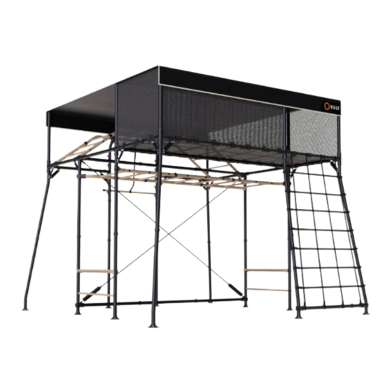
NINJA QUEST 2 PRO
L
Assembly Manual
ATTENTION!
SAFETY INFORMATION, INSTALLATION, CARE AND MAINTENANCE
INSTRUCTIONS. READ PRIOR TO ASSEMBLING AND USING THE PRODUCT.
Vuly cares about safety.
Adult supervision is required at all times whilst equipment is in use.
Scan this QR code
If you have any feedback regarding our instructions, feel free to email
or visit vulyplay.com/install for
instructions@vulyplay.com
so that we can continue to improve.
step-by-step video instructions
1-246431
Advertisement
Table of Contents

Related Manuals for Vuly NINJA QUEST 2 PRO


Summary of Contents for Vuly NINJA QUEST 2 PRO
- Page 1 NINJA QUEST 2 PRO Assembly Manual ATTENTION! SAFETY INFORMATION, INSTALLATION, CARE AND MAINTENANCE INSTRUCTIONS. READ PRIOR TO ASSEMBLING AND USING THE PRODUCT. Vuly cares about safety. Adult supervision is required at all times whilst equipment is in use. Scan this QR code If you have any feedback regarding our instructions, feel free to email or visit vulyplay.com/install for...
- Page 2 The following Conditions of Sale will apply to and bind the part of Vuly, its office bearers, directors, employees or purchasers of any Vuly Play ABN: 48 655 129 623 & EIN: 99- agents. 2968094 (“Vuly”) product.
-
Page 3: Table Of Contents
Contents Read and follow all instructions in this manual before using your system, and do not use it in any way that is not described in this manual. Responsibility rests with the owner and supervisors of the product to make sure that all users are aware of the practices specified in this manual. -
Page 4: Care And Maintenance
• Ensure that moving steel components remain well COMPONENTS WILL DETERIORATE OVER TIME. lubricated. Record your date of purchase: • Use only parts and accessories recommended by Vuly. 1.2. Rust and corrosion • Be aware of, and check, areas that are particularly prone to rusting: º... -
Page 5: Usage And Behaviour
• Install the system on level ground and in a well- lit area, Vuly cares about safety. no less than 2 m (6 ft) from any structure or obstruction – such as a fence, garage, house, overhanging branches, laundry lines, or electrical wires. -
Page 6: Pre-Assembly
3.0. Pre-assembly 3.1. Size Reference 3.0m 3.2. Tips & Tricks 3.2.1. Joiner Fitting To align the joiner holes with the holes in the frame tube, take the large 6mm Allen key and insert it into the top hole in the joiner tube then twist until the holes align. - Page 7 3.2.2. Uneven Ground Ensure that ground at the installation location is level and clear of obstructions. Installing on an uneven surface can cause misallignment and instability. 3.2.3. Cap Removal Ensure that protective caps on reinforcement tabs are removed before assembly. 3.2.4.
-
Page 8: Road Map
3.3. Road Map PAGE 17 PAGE 30 PAGE 37 PAGE 46 PAGE 41 PAGE 68 PAGE 74 PAGE 77 PAGE 103 PAGE 95... -
Page 9: Parts And Components
3.4. Parts and components BOX B M10*45 ROUND BARREL NUT PLASTIC WASHER TUBE TO TUBE PLASTIC FOOT ADJUSTABLE JOINER JOINER 1-246431... - Page 10 BOX C M10 NYLON NUT M10*16 REINFORCEMENT TUBE TO TUBE ROUND BARREL NUT PLATE JOINER...
- Page 11 BOX PA3 ROUND M10*45 M8*50 BARREL NUT TUBE TO TUBE JOINER ANCHOR M8*30 PLASTIC WASHER BARREL NUT 1-246431...
- Page 12 BOX P1 ADJUSTABLE JOINER CROSS JOINER (CROSS BRACE)
- Page 13 BOX N1 1-246431...
- Page 14 BOX N2...
- Page 15 BOX N3 ROUND M10*45 M8*50 BARREL NUT TUBE TO TUBE JOINER ANCHOR M8*30 PLASTIC WASHER BARREL NUT 1-246431...
- Page 16 BOX NP1 SALMON LADDER BAR ADJUSTABLE JOINER...
- Page 17 BOX NP2 PLASTIC STEP TUBE TO TUBE 5 WAY JOINER JOINER SHADE COVER PLASTIC FOOT 4 WAY JOINER 4 WAY JOINER (CROSS BARCE) ANCHOR ROUND 17MM BARREL NUT M8*40 ALLEN KEY ALLEN KEY SPANNER 1-246431...
- Page 18 BOX NP3 CROSS BRACE ADJUSTABLE JOINER ROPE SAFETY NET TUBE TO TUBE JOINER OVERPASS CROSS BRACE ADJUSTER ROUND BARREL NUT BARREL NUT CARGO NET FOAM COVER NINJA REINFORCEMENT M10*45 M8*50 PLATE REINFORCEMENT M8*30 M10*16 PLASTIC WASHER M10 NYLON NUT PLATE...
-
Page 19: Assembly Instructions
4.0. Assembly Instructions 4.1. HIDEOUT ASSEMBLY ENSURE THAT AS YOU ASSEMBLE THE PRODUCT, YOU FIRMLY TIGHTEN ALL NUTS AND BOLTS, UNLESS DIRECTED. Required Components Poles Joiners Fasteners V1 ........x1 4 Way ......x2 M8*50 ......x13 V1R ........x2 5 Way ......x2 Hex Barrel Nut ..... x10 H1 ........x2 Cross Joiner ....x1 Round Barrel Nut ...x3... - Page 20 NOTE: Ensure safety net entrance is aligned to overpass handles WARNING! Ensure that all velcros are threaded through the safety net before continuing...
- Page 21 WARNING! Ensure that all loops are threaded through the safety net before continuing 1-246431...
- Page 22 5 Way Joiner 4 Way Joiner...
- Page 23 6mm Allen Key M8*50 Barrel Nut NOTE: Ensure that Holes between the Tubes and Joiners are correctly aligned 1-246431...
- Page 24 NOTE: For best results, push tube through overpass loops using a twisting action...
- Page 25 1-246431...
- Page 26 6mm Allen Key 5mm Allen Key...
- Page 27 1-246431...
- Page 29 1-246431...
- Page 31 1-246431...
-
Page 32: Monkey Bar Assembly
4.2. MONKEY BAR ASSEMBLY ENSURE THAT AS YOU ASSEMBLE THE PRODUCT, YOU FIRMLY TIGHTEN ALL NUTS AND BOLTS, UNLESS DIRECTED. Required Components Tubes Joiners Fasteners B1 ........x4 Adjustable Joiner ...x4 M8*50 ......x8 B2 ........x2 Tube to Tube ....x4 M10*45 ......x18 V3R .......x4 Plastic Washer ....x18 Tools... - Page 33 B1 x4 B2 x2 R1 x9 WARNING! Ensure that Round Barrel Nuts are used on Tube to Tube Joiners 1-246431...
- Page 34 6mm Allen Key 5mm Allen Key NOTE: Use a 6mm Allen Key on the Bolt and 5mm Allen Key on the Barrel nut when tightening...
- Page 35 WARNING! Ensure the orientation indicator slot of each rung is pointing horizontally 1-246431...
- Page 36 NOTE: Insert Fasteners into Adjustable Joiner and screw until fi nger tight...
- Page 37 NOTE: Adjustable Joiner should rest on the rivet in the tube 1-246431...
- Page 38 WARNING: Ensure that reinforcement tabs are facing outwards NOTE: Do not tighten clamping bolts for Adjustable Joiners as this stage.
-
Page 39: H-Frame Assembly
4.3. H-FRAME ASSEMBLY ENSURE THAT AS YOU ASSEMBLE THE PRODUCT, YOU FIRMLY TIGHTEN ALL NUTS AND BOLTS, UNLESS DIRECTED. Required Components Poles Joiners Fasteners V2 ........x4 Adjustable(Cross Brace) x2 M10x45 ......x8 R2 ........x2 M10 Plastic Washer ..x8 Tools R3 ........x2 M8x30 ......x2 6mm Allen Key ....x2 Misc... - Page 40 NOTE: Insert Fasteners into Adjustable Joiner and screw until fi nger tight Adjustable Joiner (Cross Brace) WARNING! Ensure Feet are locked into H-Frame and Cross Brace attachment point is facing upwards...
- Page 41 WARNING! Ensure that Step Tubes are in correct orrientation as noted above NOTE: Do not fullly tighten fasteners. Repeat steps 1 to 4 to construct a second H-Frame 1-246431...
- Page 42 NOTE: Rotate one of the Adjustable Joiners and lightly tighten clamp bolts for later adjustment.
-
Page 43: Span
4.4. 3M SPAN ENSURE THAT AS YOU ASSEMBLE THE PRODUCT, YOU FIRMLY ENSURE THAT AS YOU ASSEMBLE THE PRODUCT, YOU FIRMLY TIGHTEN ALL NUTS AND BOLTS, UNLESS DIRECTED. TIGHTEN ALL NUTS AND BOLTS, UNLESS DIRECTED. Required Components Poles Joiners Fasteners H1 ........x3 Tube to Tube ....x4 M8*50 ......x4... - Page 45 1-246431...
- Page 46 WARNING: Use a protective cap to cover the reinforcement tab on the H1R tube.
- Page 47 1-246431...
-
Page 48: Frame Assembly
4.5. FRAME ASSEMBLY ENSURE THAT AS YOU ASSEMBLE THE PRODUCT, YOU FIRMLY TIGHTEN ALL NUTS AND BOLTS, UNLESS DIRECTED. Required Components Fasteners Tubes Joiners V1 ........x2 Tube to Tube ....x8 M8*50 ......x31 Hex Barrel Nut .....x23 A1 ........x2 4 Way ......x2 A2 ........x1 Round Barrel Nut ....x8 Sub-Assemblies... - Page 49 1-246431...
- Page 50 WARNING: Minimum of three people required to flip frame over.
- Page 51 NOTE: Ensure that A2 Tubes are placed in the corners and the A3 Tube is placed in the Cross Joiner 1-246431...
- Page 52 45˚ 45˚ NOTE: Ensure that corner Tubes are angled out at 45 degrees WARNING! Ensure that reinforcement tabs are facing outwards as indicated above...
- Page 53 NOTE: Secure all inserted tubes with a Hex Barrel Nut and Bolt WARNING! Ensure that Adjustable Joiner Clamping Bolts are sufficiently tightened to prevent slipping 1-246431...
- Page 54 NOTE: All braces must be securely installed before proceeding to the next step.
- Page 55 WARNING: Minimum of three people required to flip frame over. 1-246431...
- Page 56 NOTE: If having difficulty inserting fasteners, back the tube out and align as shown in “3.2.1. Joiner Fitting” on page 4...
- Page 57 1-246431...
- Page 59 WARNING! Ensure that Feet are correctly locked into Tubes before proceeding 1-246431...
- Page 60 WARNING! These step requires a minimum of three people. Lift with a straight back.
- Page 61 H-FRAME NOTE: Ensure that Adjustable Joiner on the H-Frame is located on the outside corner NOTE: Ensure that the A1 Leg Subassembly with an Adjustable Joiner is used for this step 1-246431...
- Page 62 NOTE: With all legs on one side attached, move to the opposite side of the Quest WARNING! These step requires a minimum of three people. Lift with a straight back.
- Page 63 H-FRAME NOTE: Ensure that Adjustable Joiner on the H-Frame is located on the outside corner NOTE: Ensure that the A1 Leg Subassembly without an Adjustable Joiner is used for this step 1-246431...
- Page 64 NOTE: Secure lower legs with Tube to Tube Joiners WARNING! Tighten all Step-Tube Fasteners on the H-Frame Sub-Assemblies...
- Page 65 1-246431...
- Page 66 NOTE: Ensure that the A4 Leg Subassembly with an Adjustable Joiner is used for this step...
- Page 67 1-246431...
- Page 68 PLASTIC STEP WARNING: Fasten bolts until secure. Do not overtighten bolts.
- Page 69 1-246431...
-
Page 70: Required Components
4.6. CROSS BRACE ENSURE THAT AS YOU ASSEMBLE THE PRODUCT, YOU FIRMLY TIGHTEN ALL NUTS AND BOLTS, UNLESS DIRECTED. Required Components Misc Tools Cross Brace Rope ...x1 17mm Spanner ....x1 Cross Brace Adjuster ..x2 Foam Cover ....x2... - Page 71 NOTE: To allow for easy attachment of the cross brace, turn to extend the turnbuckles to full length CROSS BRACE ROPE 1-246431...
- Page 73 1-246431...
- Page 74 NOTE: Turn Cross Brace adjuster until bolts come together and there is suffi cient rope tension.
- Page 75 FOAM COVER 1-246431...
-
Page 76: Cargo Net
4.7. CARGO NET ENSURE THAT AS YOU ASSEMBLE THE PRODUCT, YOU FIRMLY TIGHTEN ALL NUTS AND BOLTS, UNLESS DIRECTED. Required Components Misc Cargo Net... - Page 77 1-246431...
- Page 78 NOTE: Tighten bottom straps as required to provide suffi cient tension to Cargo Net.
-
Page 79: Frame Continued
4.8. FRAME CONTINUED ENSURE THAT AS YOU ASSEMBLE THE PRODUCT, YOU FIRMLY TIGHTEN ALL NUTS AND BOLTS, UNLESS DIRECTED. Required Components Tubes Joiners Fasteners L1 ........x1 4 Way ......x2 M8*50 .......x30 L2 ........x1 Adjustable Joiner ..x6 M10*45 ...... - Page 80 WARNING! Ensure that tabs on L1 and H3R Tubes are facing each other...
- Page 81 R1x11 WARNING! Ensure that orientation indicator slot of each rung follows along each Tubes WARNING! Ensure that indicators on B4 tubes are facing inward 1-246431...
- Page 83 1-246431...
- Page 84 WARNING! Ensure that adjustable joiners are not tightened...
- Page 85 WARNING! Ensure that tabs on V6 Tubes are facing downwards 1-246431...
- Page 86 WARNING: Minimum of four people required to fl ip frame over.
- Page 87 WARNING: Slide highlighted assemblies into 4 Way Joiners on each side. Loosen Clamp Bolt if required. 1-246431...
- Page 88 WARNING! Ensure that all joiners are tightened WARNING: Minimum of four people required to fl ip frame...
- Page 89 45˚ NOTE: Ensure that corner Tubes are angled out at 45 degrees 1-246431...
- Page 90 45˚ 45˚...
- Page 91 WARNING: Minimum of four people required to tip the frame 1-246431...
- Page 92 1.3m WARNING! With a minimum of four people, lift and position the frame as above...
- Page 93 WARNING! With a minimum of four people, lift and align the frame as above WARNING! Ensure ladder is held at all times 1-246431...
- Page 94 WARNING! Ensure ladder is held at all times...
- Page 95 WARNING! Use reinforcement plate with ‘‘Up arrow’’ 1-246431...
- Page 96 SALMON LADDER WARNING: Use the Triple Hook and Loop strap to secure the Salmon Ladder to the frame NOTE: Ensure that all fasteners are tight and secure...
-
Page 97: Required Components
4.9. SHADE COVER ENSURE THAT AS YOU ASSEMBLE THE PRODUCT, YOU FIRMLY TIGHTEN ALL NUTS AND BOLTS, UNLESS DIRECTED. Required Components Misc Tools Shade Cover ....x1 Ladder ......x1 1-246431... - Page 98 NOTE: Align batch tag on Shade Cover with right side of Hideout entry. WARNING! Pull fi rmly and ensure that clip is clicked into position.
- Page 99 1-246431...
- Page 101 1-246431...
- Page 103 1-246431...
-
Page 105: Anchoring
4.10. ANCHORING ENSURE THAT AS YOU ASSEMBLE THE PRODUCT, YOU FIRMLY TIGHTEN ALL NUTS AND BOLTS, UNLESS DIRECTED. Required Components Misc Tools Anchor Kit ......x1 Hammer ......x1 13mm Socket Driver ..x1 1-246431... - Page 106 WARNING! Ensure that ground at the installation location is level and clear of obstructions. Installing on an uneven surface can cause misallignment and instability. 13mm WARNING! To secure, drive anchors into the ground with a 13mm driver or a hammer...
- Page 107 1-246431...
- Page 108 CONGRATULATIONS! You have assembled your Quest 2 playset!
-
Page 109: Product Registration
6.0. Half-price replacement 7.1.1. Second-hand purchases parts Vuly warranties apply only for the original purchaser, to a Vuly offers half-price replacement parts to all customers product purchased from Vuly Play or an Authorised Reseller. for the lifetime of their purchase through the Half-Price On-selling a Vuly product voids and all warranties. -
Page 110: Warranty Claims
Warranty Claim will not be assessed. This warranty will be void if the product is used for any other Vuly may take up to 7 days to process Warranty Claims activity besides those for which it was intended, or used in upon a completed submission. -
Page 111: Missing Parts
Goods fail to be of acceptable quality and the failure does not amount to a major failure. 8.0. Missing parts If a customer believes that a Vuly product does not include all necessary parts, they must immediately lodge a Missing Parts Claim at vulyplay.com/support. - Page 112 See vulyplay.com/terms for the most recent Vuly warranty policies, terms and conditions.
Need help?
Do you have a question about the NINJA QUEST 2 PRO and is the answer not in the manual?
Questions and answers