Table of Contents
Advertisement
Quick Links
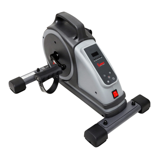
SMART MOTORIZED MINI
EXERCISE BIKE
SF-B020029 SMART
USER MANUAL
DO NOT STAND ON THE UNIT!
IMPORTANT! Please retain owner's manual for maintenance and adjustment instructions.
Your satisfaction is very important to us, PLEASE DO NOT RETURN UNTIL YOU HAVE
CONTACTED US: support@sunnyhealthfitness.com or 1- 877 - 90SUNNY (877-907-8669).
Advertisement
Table of Contents

Related Manuals for Sunny Health & Fitness SF-B020029 SMART


Summary of Contents for Sunny Health & Fitness SF-B020029 SMART
- Page 1 SMART MOTORIZED MINI EXERCISE BIKE SF-B020029 SMART USER MANUAL DO NOT STAND ON THE UNIT! IMPORTANT! Please retain owner’s manual for maintenance and adjustment instructions. Your satisfaction is very important to us, PLEASE DO NOT RETURN UNTIL YOU HAVE CONTACTED US: support@sunnyhealthfitness.com or 1- 877 - 90SUNNY (877-907-8669).
-
Page 2: Important Safety Information
IMPORTANT SAFETY INFORMATION Thank you for purchasing the Motorized Smart Electromagnetic Mini Exercise Bike. Please read the operating instructions carefully before use. Safe and effective use can only be achieved if the equipment is assembled, maintained, and used properly. It is your responsibility to ensure that all users of the equipment are informed of all warnings and precautions. -
Page 3: Pre-Assembly Check List
PRE-ASSEMBLY CHECK LIST Description Spec. Qty. Description Spec. Qty. Main Frame Rear Stabilizer Power Cord Hardware Package Left Pedal Battery Thank You Card Right Pedal 11-1 Remote Control User Manual Front Stabilizer... -
Page 4: Hardware Package
HARDWARE PACKAGE #14 M8*42 4PCS #39 S13-S14-S15 1PC #15 ID8.2*OD16*1.5 4PCS #40 S17-S19 1PC #17 M8 4PCS Ordering Replacement Parts (U.S. and Canadian Customers only) Please provide the following information in order for us to accurately identify the part(s) needed: ... - Page 5 ASSEMBLY INSTRUCTIONS We value your experience using Sunny Health and Fitness products. For assistance with parts or troubleshooting, please contact us at support@sunnyhealthfitness.com or 1-877-90SUNNY (877-907-8669). STEP 1: #14 M8*42 4PCS #15 ID8.2*OD16*1.5 4PCS Attach Front Stabilizer (No. 19) to the #17 M8 4PCS Main Frame (No.
- Page 6 We value your experience using Sunny Health and Fitness products. For assistance with parts or troubleshooting, please contact us at support@sunnyhealthfitness.com or 1-877-90SUNNY (877-907-8669). STEP 2: #21R 1/2"-20 1PC NOTE: The Left & Right Pedals (No. 7L & No. 7R) are marked “L” and “R” for Left and #21L 1/2"-20 1PC Right.
- Page 7 We value your experience using Sunny Health and Fitness products. For assistance with parts or troubleshooting, please contact us at support@sunnyhealthfitness.com or 1-877-90SUNNY (877-907-8669). STEP 3: 41-1 7L-1 41-1 Insert the fixing hole (#A) of the Pedal Strap (No. 41-1) into the card slot (#7L-1) of the Left Pedal (No.
- Page 8 We value your experience using Sunny Health and Fitness products. For assistance with parts or troubleshooting, please contact us at support@sunnyhealthfitness.com or 1-877-90SUNNY (877-907-8669). STEP 4: 41-1 Insert the fixing hole (#A) of the Pedal Strap (No. 41-1) into the card slot (#7R-1) of the 41-1 Right Pedal (No.
- Page 9 We value your experience using Sunny Health and Fitness products. For assistance with parts or troubleshooting, please contact us at support@sunnyhealthfitness.com or 1-877-90SUNNY (877-907-8669). STEP 5: Plug the Power Cord (No. 4) into the Outlet (No. 13) on the Main Frame (No. The assembly is complete!
-
Page 10: Important Electrical Information
IMPORTANT ELECTRICAL INFORMATION WARNING: This cycle requires a power source of 120V in order to properly operate. For your safety as well as the safety of others, please verify that the power source is correct before powering in the equipment. Any power supply source above or below this level could cause significant damage to the equipment and/or user. -
Page 11: Battery Installation And Replacement
BATTERY INSTALLATION & REPLACEMENT BATTERY INSTALLATION: 1. Press point a with a pen or other something sharp, then push down the battery cover on the back of the Remote Control (No. 11-1) to remove the battery cover. (as shown by the arrow b) 2. -
Page 12: Display Console
DISPLAY CONSOLE BLUETOOTH 1. The Bluetooth icon will flash when the console is on. If no Bluetooth connection is established within 3 minutes, the Bluetooth icon will turn off. 2. The Bluetooth icon will stay on when it is connected. WIRELESS HEART RATE 1. -
Page 13: Function Keys
FUNCTION KEYS Start/Pause Start and pause bike Mode Changes between automatic and manual Direction Changes the direction forward or backward Speed+/- Select key for increasing or decreasing speed (18 speed levels) WARNINGS AND INSTRUCTIONS Do not stand on the bike. Only use while seated in a chair. ... - Page 14 OPERATING INSTRUCTIONS 1. Plug in the Power Cable (No. 4). Turn on the Power Switch (No. 5). The bike will beep and LED display will show “OFF”. This is standby mode. 2. Press the Start/Pause button on the console or the remote control to start the bike, it will begin in manual mode.
- Page 15 P1 MODE: Based on speed Level 1, the pedals move 13 times forward, 13 times backwards, 13 times forward based, 13 times backwards and so on. P2 MODE: The pedals move forward first then the speed will be increasing from Level 1 to Level 9 gradually.
-
Page 16: Remote Control
REMOTE CONTROL FUNCTION KEYS Start/Pause: Start and pause elliptical MODE: Changes between automatic and manual Direction: Changes the direction forward or backward Speed: Select + key for increasing or – for decreasing speed (18 speed levels) Pause REMOTE CONTROL PAIRING METHOD: 1. - Page 17 This device complies with Part 15 of the FCC Rules. Operation is subject to the following two conditions: (1) this device may not cause harmful interference, and (2) this device must accept any interference received, including interference that may cause undesired operation. NOTE: This equipment has been tested and found to comply with the limits for a Class B digital device, pursuant to Part 15 of the FCC Rules.
-
Page 18: User-Maintenance Instruction
USER-MAINTENANCE INSTRUCTION Caution:There are no serviceable parts in the appliance, any servicing should be performed by an authorized service person. When the appliance is not in use, disconnect the power supply, storage of the power cord and the total appliance in a dry location where children cannot touch or in play area(s). WARNING The machine is intended to use in a sitting position only. -
Page 19: App Connection
APP CONNECTION: Connect Smart Equipment to SunnyFit App: 1. Scan to download SunnyFit from the app store: 2. Ensure that the Bluetooth function is turned on from your mobile device. 3. If this is your first time using the SunnyFit app, follow the in-app instructions to register for your free SunnyFit account and log in. -
Page 20: Parts List
PARTS LIST Description Spec. Description Spec. Main Frame Left Nylon Nut 1/2”-20 Right Nylon Nut 1/2”-20 Left Crank Screw ST3.5*15 Toothed Lock Right Crank Washer Power Cord Screw ST4.2*19 Power Switch Flange Nut Rubber Pad End Cap Left Pedal Spring Washer Right Pedal 3P Data Line Left Belt Cover... -
Page 21: Exploded Diagram
EXPLODED DIAGRAM 41-1 11-1 41-1 Version 1.1...
Need help?
Do you have a question about the SF-B020029 SMART and is the answer not in the manual?
Questions and answers