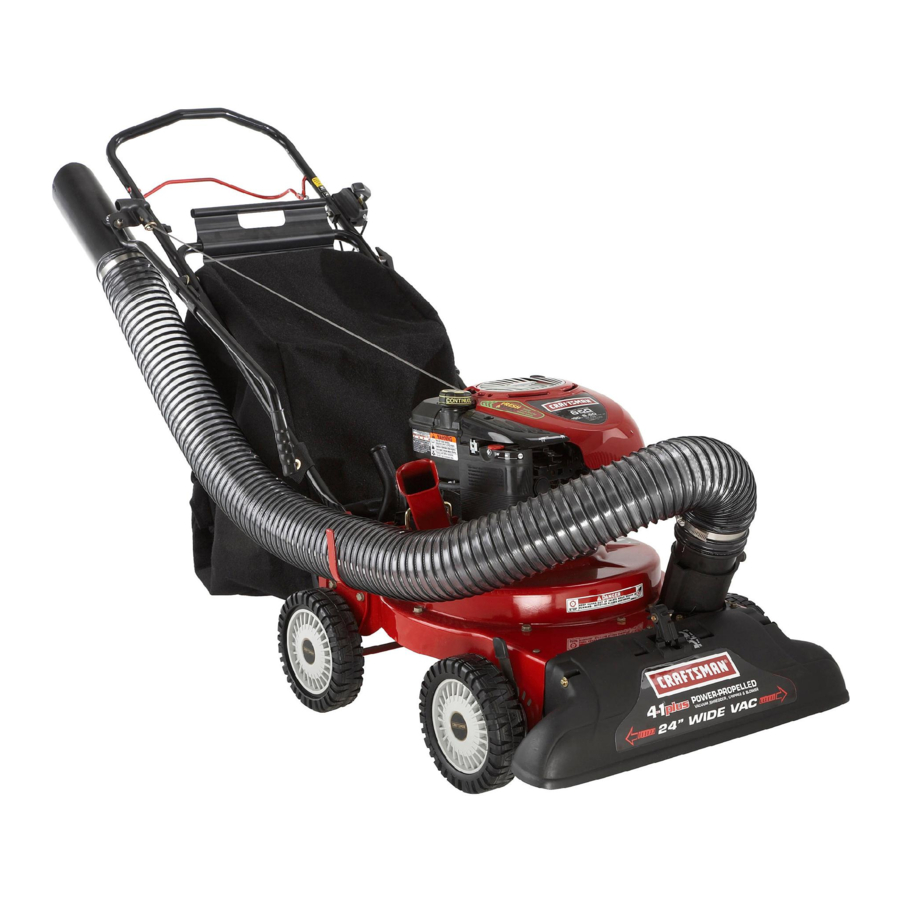
Craftsman 675 Series, 247.77013 Manual
- Operator's manual (96 pages) ,
- Owner's manual (49 pages) ,
- Operator's manual (56 pages)
Advertisement
- 1 PRODUCT SPECIFICATIONS
- 2 SAFETY INSTRUCTIONS
- 3 ASSEMBLY
- 4 OPERATION
- 5 SERVICE AND MAINTENANCE
- 6 OFF-SEASON STORAGE
- 7 TROUBLESHOOTING
- 8 PARTS LIST
- 9 Documents / Resources
PRODUCT SPECIFICATIONS
| Engine Series: | 675 |
| Engine Oil Type: | SAE 30 |
| Engine Oil Capacity: | 18 ounces |
| Fuel Capacity: | 1½ Quarts |
| Spark Plug: | Champion®RJ19LM |
| Spark Plug Gap: | .020" |
SAFETY INSTRUCTIONS

Before using this product, read this manual and follow all safety rules and operating instructions.

This symbol points out important safety instructions which, if not followed, could endanger the personal safety and/or property of yourself and others, Read and follow all instructions in this manual before attempting to operate this machine, Failure to comply with these instructions may result in personal injury, When you see this s mbol, HEED ITS WARNING!
CALIFORNIA PROPOSITION 65
Engine Exhaust, some of its constituents, and certain vehicle components contain or emit chemicals known to State of California to cause cancer and birth defects or other reproductive harm.

This machine was built to be operated according to the safe operæ tion practices in this manual. As with any type of power equipment, carelessness or error on the part of the operator can result in serious injury, This machine is capable of amputating fingers, hands, toes and feet and throwing debris. Failure to observe the following safety instructions could result in serious injury or death.
Your Responsibility—Restrict the use of this power machine to persons who read, understand and follow the warnings and instructions in this manual and on the machine,
SAVE THESE INSTRUCTIONS!
TRAINING
- Read, understand, and follow all instructions on the machine and in the manual before attempting to assemble and operate. Keep this manual in a safe place for future and regular reference and for ordering replacement parts.
- Read the Operator's Manual and follow all warnings and safety instructions. Failure to do so can result in serious injury to the operator and/or bystanders, For questions call, 1-8004MY-HOME.
- Be familiar with all controls and their proper operation, Know how to stop the machine and disengage them quickly.
- Never allow children under 16 years of age to operate this machine, Children 16 and over should read and understand the instructions and safe operation practices in this manual and on the machine and be trained and supervised by an adult.
- Never allow adults to operate this machine without proper instruction.
- Keep bystanders, pets, and children at least 75 feet from the machine while it is in operation, Stop machine if anyone enters the area.
- Never run an engine indoors or in a poorly ventilated area. Engine exhaust contains carbon monoxide, an odorless and deadly gas.
- Do not put hands and feet near rotating parts or in the feeding chambers and discharge opening. Contact with the rotating impeller can amputate fingers, hands, and feet.
- Never attempt to unclog either the feed intake or discharge opening, remove or empty bag, or inspect and repair the machine while the engine is running, Shut the engine off and wait until all moving parts have come to a complete stop, Disconnect the spark plug wire and ground it against the engine.
PREPARATION
- Thoroughly inspect the area where the equipment is to be used. Remove all rocks, bottles, cans, or other foreign objects which could be picked up or thrown and cause personal injury or damage to the machine.
- Always wear safety glasses or safety goggles during operation and while performing an adjustment or repair, to protect your eyes, Thrown objects which ricochet can cause serious injury to the eyes.
- Wear sturdy, rough-soled work shoes and close-fitting slacks and shirts, Loose fitting clothes or jewelry can be caught in movable parts. Never operate this machine in bare feet or sandals, Wear leather work gloves when feeding material in the chipper chute.
- Before starting, check all bolts and screws for proper tightness to be sure the machine is in safe working condition. Also, visually inspect machine for any damage at frequent intervals.
- Maintain or replace safety and instructions labels, as necessary.
Safe Handling of Gasoline:
To avoid personal injury or property damage use extreme care in handling gasoline, Gasoline is extremely flammable and the vapors are explosive. Serious personal injury can occur when gasoline is spilled on yourself or your clothes which can ignite, Wash your skin and change clothes immediately.
- Use only an approved gasoline container.
- Never fill containers inside a vehicle or on a truck or trailer bed with a plastic liner. Always place containers on the ground away from your vehicle before filling.
- When practical, remove gas-powered equipment from the truck or trailer and refuel it on the ground. If this is not possible, then refuel such equipment on a trailer with a portable container, rather, than from a gasoline dispenser nozzle.
- Keep the nozzle in contact with the rim of the fuel tank or container opening at all times until fueling is complete. Do not use a nozzle lock-open device.
- Extinguish all cigarettes, cigars, pipes and other sources of.
- Never fuel machine indoors.
- Never remove gas cap or add fuel while the engine is hot or running. Allow engine to cool at least two minutes before refueling.
- Never over fill fuel tank. Fill tank to no more than ½ inch below bottom of filler neck to allow space for fuel expansion.
- Replace gasoline cap and tighten securely.
- If gasoline is spilled, wipe it off the engine and equipment. Move unit to another area. Wait 5 minutes before starting the engine,
- To reduce fire hazards, keep machine free of grass, leaves, or other debris build-up. Clean up oil or fuel spillage and remove any fuel soaked debris.
- Never store the machine or fuel container inside where there is an open flame, spark or pilot light as on a water heater, space heater, furnace, clothes dryer or other gas appliances.
OPERATION
- Do not put hands and feet near rotating parts or in the feeding chambers and discharge opening. Contact with the rotating impeller can amputate fingers, hands, and feet.
- Before starting the machine, make sure the chipper chute, feed intake, and cutting chamber are empty and free of all debris.
- Thoroughly inspect all material to be shredded and remove any metal, rocks, bottles, cans, or other foreign objects which could cause personal injury or damage to the machine.
- If the impeller strikes a foreign object or if your machine should start making an unusual noise or vibration, immediately shut the engine oft Allow the impeller to come to a complete stop. Disconnect the spark plug wire, ground it against the engine and perform the following steps:
- Inspect for damage.
- Repair or replace any damaged parts,
- Check for any loose parts and tighten to assure continued safe operation.
- Do not allow an accumulation of processed material to build up in the discharge area. This can prevent proper discharge and result in kickback of material through the feed opening, Do not attempt to shred or chip material larger than specified on the machine or in this manual Personal injury or machine damage could result.
- Never attempt to unclog either the feed intake or discharge opening while the engine is running. Shut the engine off, wait until all moving parts have stopped, disconnect the spark plug wire and ground it against the engine before clearing debris, Never operate without vacuum bag and discharge chute properly attached to the machine, Never empty or change vacuum bag while the engine is running, Vacuum bag must be kept closed at all times during operation.
- Never operate without either the inlet nozzle or optional hose attachment (if applicable) properly attached to the machine. Never attempt to attach or change either attachment while the engine is running.
- Keep all guards, deflectors and safety devices in place and operating properly.
- Keep your face and body back and to the side of the chipper chute while feeding material into the machine to avoid accidental kickback injuries.
- Never operate this machine without good visibility or light Always be sure of your footing and keep a firm hold on the handles. Do not operate this machine on a paved, gravel or non-level surface.
- Do not operate this machine while under the influence of alcohol or drugs.
- Muffler and engine become hot and can cause a burn. Do not touch.
- Never pick up or carry machine while the engine is running.
- If situations occur which are not covered in this manual, use care and good judgement. Contact Customer Support for assistance and the name of the nearest service dealer.
MAINTENANCE & STORAGE
- Never tamper with safety devices. Check their proper operation regularly.
- Check bolts and screws for proper tightness at frequent intervals to keep the machine in safe working condition. Also, visually inspect machine for any damage and repair, if needed.
- Before cleaning, repairing, or inspecting, stop the engine and make certain the impeller and all moving parts have stopped. Disconnect the spark plug wire and ground it against the engine to prevent unintended starting.
- Do not change the engine governor settings or overspeed the engine. The governor controls the maximum safe operating speed of the engine.
- Maintain or replace safety and instruction labels, as necessary.
- Follow this manual for safe loading, unloading, transporting, and storage of this machine.
- Never store the machine or fuel container inside where there is an open flame, spark or pilot light such as a water heater, furnace, clothes dryer, etc.
- Allow machine to cool at least 5 minutes before storing.
- Always refer to the operator's manual for proper instructions on off-season storage.
- If the fuel tank has to be drained, do this outdoors.
- Observe proper disposal laws and regulations for gas, oil, etc, to protect the environment.
- According to the Consumer Products Safety Commission (CPSC) and the U.S. Environmental Protection Agency (EPA), this product has an Average Useful Life of seven (7) years, or 60 hours of operation. At the end of the Average Useful Life have the machine inspected annually by an authorized service dealer to ensure that all mechanical and safety systems are working properly and not worn excessively, Failure to do so can result in accidents, injuries or death.
DO NOT MODIFY ENGINE
To avoid serious injury or death, do not modify engine in any way. Tampering with the governor setting can lead to a runaway engine and cause it to operate at unsafe speeds. Never tamper with factory setting of engine governor.
NOTICE REGARDING EMISSIONS
Engines which are certified to comply with California and federal EPA emission regulations for SORE (Small Off Road Equipment) are certified to operate on regular unleaded gasoline, and may include the following emission control systems: Engine Modification (EM), Oxidizing Catalyst (OC), Secondary Air Injection (SAD and Three Way Catalyst (TWC) if so equipped.
SPARK ARRESTOR
This machine is equipped with an internal combustion engine and should not be used on or near any unimproved forest-covered, brushcovered or grass-covered land unless the engine's exhaust system is equipped with a spark arrestor meeting applicable local or state laws (if any).
If a spark arrestor is used, it should be maintained in effective working order by the operator. In the State of California the above is required by law (Section 4442 of the California Public Resources Code). Other states may have similar laws. Federal laws apply on federal lands, A spark arrestor for the muffler is available through your nearest Sear Parts and Repair Service Center.
SAFETY SYMBOLS
This page depicts and describes safety symbols that may appear on this product Read, understand, and follow all instructions on the machine before attempting to assemble and operate.
| Symbol | Description |
 | READ THE OPERATOR'S MANUAL(S) Read, understand, and follow all instructions in the manual(s) before attempting to assemble and operate |
 | ROTATING BLADES Keep hands out of inlet and discharge openings while machine is running. There are rotating blades inside. |
 | BYSTANDARDS Keep bystanders, pets, and children at least 75 feet from the machine while it is in operation. Stop machine if anyone enters the area. |
 | BYSTANDARDS Keep bystanders, pets, and children at least 75 feet from the machine while it is in operation. Stop machine if anyone enters the area. |
 | THROWN OBJECTS This machine may pick up and throw and objects which can ricochet. |
 | EYE PROTECTION Always wear safety glasses or safety goggles when operating this machine. |
 | GASOLINE IS FLAMMABLE Allow the engine to cool at least two minutes before refueling. |
 | CARBON MONOXIDE Never run an engine indoors or in a poorly ventilated area. Engine exhaust contains carbon monoxide, an odorless and deadly gas. |
SAFETY LABELS

ASSEMBLY

This unit is shipped without gasoline or oil in the engine,
Be certain to service engine with gasoline and oil as instructed in the Operation section of this manual before operating your machine.
 NOTE: Reference to right and left hand side of the Yard Vacuum is observed from the operating position looking forward to the front of the machine.
OPENING CARTON
- Cut each corner of the carton vertically from top to bottom.
- Remove all loose parts.
- Remove loose packing materia.
REMOVING UNIT FROM CARTON
- Lift unit from the rear to detach it from underlying carton material and roll unit out of carton.
- Check carton thoroughly for any other loose parts.
NOTE: Make sure not to crimp cables while removing loose parts or the entire unit from the carton.
LOOSE PARTS IN CARTON
(See Figure 1)

Figure 1
- Upper and Lower Handle
- Hose Assembly
- Safety Glasses
- Engine Oil (May be located in bag)
- Bag
- Blower Chute
- Operator's Manual
ATTACHING THE HANDLE
- Remove the hairpin clips from the handle brackets and remove the carriage screws and wing nuts from the lower handle.
- Place the bottom holes in lower handle over the pins on the handle brackets and secure with hairpin clips. See Figure 2

Figure 2 - Insert carriage screws through upper hole in lower handle from the inside and secure with wing nuts, See Figure 2.
- Place the bottom holes in lower handle over the pins on the handle brackets and secure with hairpin clips. See Figure 2
-
- Unfold the upper handle until it aligns with lower handle. Make sure the rope guide is on the right side of upper handle. See Figure 3.
![]()
Make sure the cables are routed outside the lower handle, Also, do not crimp the cables while lifting up the handles, - Secure the two handles by tightening the handle knobs (carriage bolts must be seated properly into the handle). See Figure 3.

Figure 3
- Unfold the upper handle until it aligns with lower handle. Make sure the rope guide is on the right side of upper handle. See Figure 3.
- Pull the two cable ties attached to the cables tight approximately 8 inches from each cable end and place the cables into the cable.
- Loosen the wing nut that secures the rope guide to the right side of upper handle.
- Pull the starter rope out of the engine slowly. See Figure 4.

Figure 4 - Slip the starter rope into the rope guide. Tighten the wing nut. See Figure 4.
- Pull the starter rope out of the engine slowly. See Figure 4.


ATTACHING THE HOSE ASSEMBLY
-
- Slide hose adapter of hose assembly into the base adapter located on the left front of the Yard Vacuum. See Figure 5.

Figure 5 - Pull spring loaded pin out on the base and align pin with the first hole (closest to the end of the tube) in the hose adapter.
- Release the pin to lock the hose in place.
- Slide hose adapter of hose assembly into the base adapter located on the left front of the Yard Vacuum. See Figure 5.
-
- Snap the hose handle first into the upper hose handle bracket and then into the lower hose handle bracket.
- Lay hose tubing in curved end of handle next to chipper chute. See Figure 6.

Figure 6


ATTACHING THE BAG
- Grasp bag handle with one hand and slide locking rod on mounting bracket with other hand toward engine. Use the end of mounting bracket as leverage when sliding the locking rod.
- Slip bag over the rim of the discharge opening and release locking rod to secure bag in place. See Figure 7.

Figure 7 - Snap bag clip to the top of the lower handle.
- Place the lower straps on the bag over the top of lower handle, hooking them on the studs. See Figure 7.
- Slip bag over the rim of the discharge opening and release locking rod to secure bag in place. See Figure 7.

NOTE:The bag/chute switch button attached to the mounting bracket must be fully depressed by the tip of front tab on bag handle when securing the bag or engine will not start.
ATTACHING THE BLOWER CHUTE
NOTE: The bag must be removed before installing the blower chute,
-
- Grasp blower chute with one hand and slide locking rod on mounting bracket with other hand toward engine, Use the end of mounting bracket as leverage when sliding the locking rod. See Figure 8.

Figure 8 - Slip blower chute over rim of discharge opening and release locking rod to secure chute in place, as in Figure 8.
- Raise the nozzle height to the highest setting when using the blower chute. Refer to nozzle height adjustment below.
- Grasp blower chute with one hand and slide locking rod on mounting bracket with other hand toward engine, Use the end of mounting bracket as leverage when sliding the locking rod. See Figure 8.

NOTE: The bag/chute switch button attached to the mounting bracket must be fully depressed by the tip of front tab on the blower chute or engine will not start
Always stop engine and disconnect spark plug wire before performing any maintenance or adjustments. Always wear safety glasses during operation or while performing any adjustments or repairs.
NOZZLE HEIGHT ADJUSTMENT
The nozzle can be adjusted to any five positions, ranging from 5/8" to 4-1/8" ground clearance. The nozzle height has to be adjusted according to yard conditions.
- Depress nozzle height adjustment lever towards wheel. See Figure 9.

Figure 9 - Move the height adjustment lever forward or backward to adjust the nozzle upwards or downwards. Make sure both levers are in the same position.
- Release lever towards deck.

NOTE: In general, raise the nozzle height to vacuum a thick layer of leaves or to operate with the blower chute. Lower the nozzle height for smoother surfaces.
OPERATION

Figure 10
Now that you have set up your yard vacuum for operation, get acquainted with its controls and features. These are described below and illustrated on this page. This knowledge will allow you to use your new equipment to its fullest potential.
The operation of any yard vacuum can result in foreign objects being thrown into the eyes, which can damage your eyes severely. Always wear the safety glasses provided with this unit or eye shields while operating or performing any adjustments or repairs on it.
CHIPPER CHUTE
Allows twigs and small branches up to 1-1/2" in diameter to be fed into the impeller for chipping. See Figure 10.
DRIVE CONTROL
Located on the underside of the upper handle, the drive control is used to engage/disengage wheels. Fully squeeze the drive control against the upper handle to engage the wheels; release to disengage, (DO NOT slip clutch).
SPEED CONTROL
Located on the left side of the upper handle, the speed control is used to select the forward speed of the yard vacuum.
Move the speed control only when the engine is running. Changing the speed control setting with the engine off can damage the yard vacuum.
NOZZLE HEIGHT ADJUSTMENT LEVER
Used to adjust the nozzle ground clearance ranging approximately from 5/8" to 4-1/8". See Figure 10.
NOZZLE
Yard waste such as leaves or pine needles can be vacuumed up through the nozzle for shredding.
HOSE ASSEMBLY
Used as an alternative to the nozzle to vacuum yard waste such as leaves or pine needles in hard to reach places. See Figure 10.
NOZZLE/ HOSE VAC LEVER
The nozzle/hose vac handle is located on top of the nozzle. Use it to switch vacuum suction between the nozzle and the hose assembly.
HOSE HANDLE
Used to guide hose assembly when vacuuming.
BAG HANDLE
Used to grasp bag in order to assist in attaching, removing, and emptying bag. See Figure 10.
BAG
Collects shredded material fed through the chipper chute or vacuumed through the nozzle or hose.
BLOWER CHUTE
When attached to unit, the blower chute is used to discharge yard waste such as leaves, pine needle, or small twigs across yard.
THROTTLE CONTROL
The throttle controls the engine speed and stop function. Through three separate positions on the lever from left to right, the operation is as follows:

CHOKE CONTROL
The choke control is used to choke the carburetor and assist in starting the engine.

STARTER HANDLE
Used to start the engine.
GAS AND OIL FILL-UP
Oil (one bottle shipped with unit)
First Time Use
- Remove oil fill dipstick.
- With the Yard Vacuum on level ground, use a funnel to empty entire contents of oil bottle provided into the engine.
- Replace oil fill dipstick and tighten.
Subsequent Uses
Only use high quality detergent oil rated with API service classification SF, SG, or Select the oil's SAE viscosity grade according to the expected operating temperature. Follow the chart below:

Although multi-viscosity oils (5W30, 10W30, etc) improve starting in cold weather, they will result in increased oil consumption when used above 32ºF. Check your engine oil level more frequently to avoid possible engine damage from running low on oil.
- Check the oil level making certain not to rub the dipstick along the inside walls of the oil fill tube. This would result in a false dipstick reading. Refill to FULL mark on dipstick, if necessary. Capacity is approximately 18 oz. Overfilling will cause the engine to smoke profusely and will result in poor engine performance.
- Replace oil fill dipstick and tighten.
- Keep oil level at FULL. Running the engine with too little oil can result in permanent engine damage.
Use extreme care when handling gasoline. Gasoline is extremely flammable and the vapors are explosive, Never fuel machine indoors or while the engine is hot or running. Extinguish cigarettes, cigars, pipes, and other sources of ignition.
Gasoline
- Remove fuel cap from the fuel tank.
- Make sure the container from which you will pour the gasoline is clean and free from rust or foreign particles. Never use gasoline that may be stale from long periods of storage in its container. Gasoline that has been sitting for any period longer than four weeks shoul dbe considered stale.
- Fill fuel tank with clean, fresh, unleaded regular gasolin eonly to approximately1-1/2 inches below top of neck to allow for fuel expansion. Do not use gasoline containing METHANOL. Replace fuel cap.
Use of alcohol blended fuels (called gasohol or using ethanol or methanol) can attract moisture which leads to separation and formæ tion of acids during storage. Acidic gas can damage the fuel system of an engine while in storage.
To avoid engine problems, the fuel system should be emptied before storage for 30 days or longer. Drain the gas tank, start the engine and let it run until the fuel lines and carburetor are empty, Use fresh fuel next season, See STORAGE Instructions for additional information.
Never use engine or carburetor cleaner products in the fuel tank or permanent damage may occur.
NOTE: Check the fuel level periodically to avoid running out of gasoline while operating the Yard Vacuum. If the unit runs out of gas as it is chipping, it may be necessary to unclog the discharge area before it can be restarted Refer to SERVICE AND MAINTENANCE section.
When moving throttle control lever, be careful of heated surfaces and sharp edges on muffler guard.
TO START ENGINE
- Attach spark plug wire and rubber boot to spark plug.
- The bag/chute switch button must be fully depressed by the tip of front tab on bag handle or blower chute for engine to start. See Figure 11.

Figure 11 - Make sure bag/chute switch wire is connected to engine and grounded to mounting bracket. See Figure 11.
- Gas tank should be filled 3/4 to full before starting.
- Move throttle control to START/RUN (Rabbit)
![]() position. See Figure 12.
position. See Figure 12.

Figure 12 - Move the choke control
![]() toward the throttle control to choke the engine's carburetor. (A warm engine may not require choking). See Figure 12.
toward the throttle control to choke the engine's carburetor. (A warm engine may not require choking). See Figure 12. - Standing behind the unit, grasp starter handle and pull rope out until you feel a drag.
- Pull the rope with a rapid, continuous, full arm stroke. Keep a firm grip on the starter handle. Let the rope rewind slowly.
- Repeat, if necessary, until engine starts. When engine starts, move choke control gradually away from the throttle control.
- If engine falters, move choke control back toward the throttle control and repeat steps 7 through 9.
- ALWAYS keep the throttle control in the START/RUN
![]() position when operating the Yard Vacuum.
position when operating the Yard Vacuum.

 position. See Figure 12.
 toward the throttle control to choke the engine's carburetor. (A warm engine may not require choking). See Figure 12.
TO STOP ENGINE
- Move throttle control lever to slow (turtle
![]() ) position.
) position.
Whenever possible, gradually reduce engine speed before stopping engine. - Move throttle control lever to STOP
![]() or OFF position.
or OFF position. - Disconnect spark plug wire and ground it to prevent accidental starting while the equipment is unattended.
 ) position.
 or OFF position.
TO EMPTY BAG
- Unhook bag straps from the lower handle.
- Unsnap bag clip from the top of lower handle. See Figure 13.

Figure 13 - Grasp bag handle with one hand and pull lock rod on mounting bracket with other hand toward engine to release,
- Lift bag off back of unit
- Twist the two buttons on the back of the bag to unlock and empty contents, See Figure 14. Hold bag handle and bag clip while emptying the contents.

Figure 14 - Compress bag opening and fold inner flap over opening.
- Fold outer flap over inner flap and insert buttons on the bag through metal outlets, See Figure 14.
- Twist the buttons to lock bag, Place bag back onto unit as instructed in the ASSEMBLY section.


TO REMOVE BLOWER CHUTE
- Grasp blower chute with one hand and pull lock rod on mounting bracket with other hand toward engine to release, Refer to Figure 8 in the ASSEMBLY section.
- Remove blower chute from over the rim of the discharge opening.
USING THE NOZZLE VACUUM
- Place nozzle/hose vac lever in the top position on the nozzle to Buttons vacuum through nozzle. See Figure 15.

Figure 15 - The spring loaded pin must be in the first hole (closest to the end of the tube) of the hose adapter to operate the nozzle vac.
- Place both hands on top of the upper handle and fully lift the drive control against the upper handle to propel the unit over yard.
- Use the speed control to choose either the high or low speed. The Figure 14 speed control may be moved either while the unit is propelling or before engaging the wheels.

Move the speed control only when the engine is running. Changing the speed control setting with the engine off can damage the yard vacuum.
Yard waste such as leaves and pine needles can be vacuumed up through the nozzle for shredding. After material has been shredded by the flail blades on the impeller assembly, it will be discharged into catcher bag or through blower chute. Do not attempt to shred or chip any material other than vegetation found in a normal yard (i.e. branches, leaves, twigs, etc.) Avoid fibrous plants such as tomato vines or palm fronds until they are thoroughly dried out. Materials such as stalks or heavy branches up to 1-1/2" in diameter may be fed into the chipper chute.
Do not attempt to shred, chip, or vacuum any material larger than specified on the machine or in this manual. Personal injury or damag to the machine could result.
The flail screen is located inside the housing in the discharge area If the flail screen becomes clogged, remove and clean as instructed in the SERVICE & MAINTENANCE section. For best performance, it is also important to keep the chipper blade sharp.
Do not at any time make any adjustments without first stopping engine and disconnecting spark plug wire.
USING THE HOSE ASSEMBLY
- Place nozzle/hose vac lever in the bottom position on the nozzle to redirect vacuum to the hose assembly. See Figure 16.

Figure 16 - The spring loaded pin must be in the second hole of the hose adapter to operate the hose assembly.
- Unhook the hose from upper handle bracket and grasp the hose handle to guide while vacuuming yard waste such as leaves or pine needles in hard to reach places.

SERVICE AND MAINTENANCE
MAINTENANCE SCHEDULE
Before performing any type of maintenance/service, disengage all controls and stop the engine Wait until all moving parts have come to a complete stop. Disconnect spark plug wire and ground it to prevent unintended starting, Always wear safety glasses during operation or while performing any adjustments or repairs.
Follow the maintenance schedule given below This chart describes service guidelines only. Use the Service Log column to keep track of completed maintenance tasks. To locate the nearest Sears Service Center or to schedule service, simply contact Sears at 1-800-4-MY-HOME®.
| Interval | Item | Service | Service Log | ||
| Each Use |
|
| |||
| 1st 5 - 8 hours |
|
| |||
| 25 hours |
|
| |||
| 50 hours |
|
| |||
| Annually or 100 hours |
|
| |||
| Before Storage |
|
| |||
 Under heavy load or in high temperatures
Always stop engine and disconnect spark plug wire before performing any maintenance or adjustments. Always wear safety glasses during operation or while performing any adjustments or repairs.
GENERAL RECOMMENDATIONS
- Always observe safety rules when performing any maintenance.
- The warranty on this yard vacuum does not cover items that have been subjected to operator abuse or negligence. To receive full value from warranty, operator must maintain the equipment as instructed here.
- Some adjustments will have to be made periodically to maintain your unit properly.
- Periodically check all fasteners and make sure these are tight.
ENGINE MAINTENANCE
Checking the Spark Plug
Clean spark plug and reset the electrode gap to 0.020" at least once a season; replace every 100 hours of operation.
- Clean area around the spark plug base, Do not sandblast spark plug, Spark plug should be cleaned by scraping or wire brushing and washing with a commercial solvent.
- Remove and inspect the spark plug, Check gap to make sure it is set at.020". See Figure 17.

Figure 17 - Replace the spark plug if electrodes are pitted, burned, or the porcelain is cracked.

Servicing the Air Cleaner
Do not use pressurized air or solvents to clean the air cleaner cartridge.
The air cleaner prevents damaging dirt, dust, etc., from entering the carburetor and being forced into the engine and is important to engine life and performance. The air cleaner consists of a pleated filter. Never run the engine without an air cleaner completely assembled.
Clean or replace the air cleaner every 25 hours of operation.
- Loosen screw and tilt plastic housing cover on side of engine down. See Figure 18.

Figure 18 - Remove air filter from plastic housing cover and replace with clean or new filter.
- Insert cover's tabs into slots in bottom of base.
- Tilt cover up into place and tighten screw.

NOTE: If the filter is torn or damaged in any way, replace it.
Checking Engine Oil
- Stop engine and wait several minutes before checking oil level, With engine on level ground, the oil must be to FULL mark on dipstick.
- Remove oil fill dipstick and wipe clean with cloth.
- Replace and tighten dipstick. Remove and check oil level Level should be at FULL mark.
- If needed, add oil slowly recheck, Do not overfill.
- Wipe dipstick clean, replace and tighten, Remove and check oil level Oil level should be at FULL line on dipstick.
Do not overfil Overfilling with oil may cause the engine to not start, or hard starting. If over the FULL mark on the dipstick, drain oil to reduce oil level to FULL mark on dipstick.
Changing Engine Oil
- Only use high quality detergent oil rated with API service classification SF, SG, or Select the oil's SAE viscosity grade according to the expected operating temperature. Refer to Operation section for viscosity chart.
- Change engine oil after the first five to eight hours of operation, and every fifty hours or every season thereafter. Change oil every twenty five hours when operating engine under heavy load or in high temperatures.
To Drain Oil
- Drain the fuel from the tank by running the engine until the fuel tank is empty.
- Disconnect spark plug wire and keep it away from spark plug.
- With engine OFF but still warm remove oil fill dipstick.
- Tip unit on its side (spark plug side up) to drain through the oil fill tube into appropriate receptacle.
Used oil is a hazardous waste product. Dispose of used oil properly, Do not discard with household waste. Check with your local authorities or Sears Service Center for safe disposal/recycling facilities.
- When engine is drained of all oil, place engine level. Refill with approximately 18 oz of fresh oil. Fill to FULL line on dipstick. Do not overfill Refer to Gas And Oil in OPERATION section.
- Replace oil fill dipstick and tighten.
- Replace spark plug wire before starting.
Temperature of muffler and nearby areas may exceed 1500 F.
Avoid these areas.
Servicing Muffler
- Inspect muffler periodically, and replace if necessary. Replacement parts for the muffler must be the same and installed in the same position as the original parts, otherwise fire can occur.
Cleaning Engine
- Daily or before every use, clean grass, chaff or accumulated debris from engine. Keep linkage, spring, and controls clean. Keep area around and behind muffler free of any combustible debris.
- Keeping engine clean allows air movement around engine.
- Engine parts should be kept clean to reduce the risk of over-heating and ignition of accumulated debris. This is especially important if cutting tall grass.
Do not use water to clean engine parts, Water could contaminate fuel system. Use a brush or dry cloth.
Carburetor Adjustment
The carburetor on this engine is not user adjustable. Contact Sears Parts & Repair for adjustment.
Engine Speed
Do not attempt to alter the engine speed by tampering with the engine's governor linkage. Doing so could result in serious personal injury and damage to the engine. The engine RPM has been set at the factory.
LUBRICATION
- Wheels - Place a few drops of SAE 30 oil on each shoulder screw once a season.
- Nozzle height adjustment levers - Lubricate nozzle height adjustment levers with light oil.
- Locking Rod - Lubricate the lock rod and compression springs which attach to the mounting bracket.
- Nozzle/Hose Vac Lever: Lubricate the nozzle/hose vac lever on top of the nozzle once a season with light oil.
CLEANING EQUIPMENT
Clean underside of the yard vacuum once a season to prevent build-up of debris. Follow steps below for this job.
- Disconnect and ground spark plug wire. Empty the fuel tank by running engine until tank is dry.
- Tip the yard vacuum so that it rests on its side, keeping the muffler side down. Hold yard vacuum firmly.
- Scrape and clean the underside of the deck and nozzle with a suitable tool, Do not spray with water.
![]()
Do not use a pressure washer or garden hose to clean your unit. These may cause damage to bearings, or the engine, The use of water will result in shortened life and reduce serviceability, - Put the yard vacuum back on its wheels on the ground.
CLEANING THE FLAIL SCREEN
If the discharge area becomes clogged, remove the flail screen and clean area as follows:
- Stop the engine. Make certain the chipper/shredder vacuum has come to a complete stop.
- Before unclogging the discharge chute, disconnect and ground the spark plug wire.
- Remove the vacuum bag or blower chute from the unit as instructed in the OPERATION section to obtain access to flail screen.
- Remove the three self tapping screws securing the belt cover, and remove belt cover. See Figure 19.

Figure 19 - Remove self tapping screw on right side of unit that attaches to the flail screen, See Figure 20.

Figure 20 - Remove hex screw on top of rear housing near mounting bracket and the flange lock nut that secures flail screen. See Figure 20.
- Remove and clean the screen by scraping or washing with water. See Figure 21.

Figure 21 - Reinstall the screen.


Before performing any type of maintenance on the machine, wait for all parts to stop moving and disconnect and ground the spark plug wire. Failure to follow this instruction could result in personal injury or property damage.
DRIVE CONTROL CABLE ADJUSTMENT
Adjust the drive control cable ifthe yard vacuum does not self propel with the drive control engaged, or if the unit hesitates while the engine maintains the same speed after approximately 20 hours of use.
To move the z-fittng of the drive control cable from its factory set position in the front hole of the drive contral to the rear hole, proceed as follows:
- Push the right side of the control out of the right hole in the upper handle. See Figure 22A.

Figure 22 - Pivot control down towards the lower handle.
- Pivot straight up to remove it from the left hole in the upper handle. See Figure 22A.
- There is now sufficient slack in the drive control cable to grasp the z-fitting with your hand and move it from the front hole to the rear hole of the drive control. See Figure 22B.
![]()
Make sure to insert the z-fitting into the rear hole as it was inserted in the front hole, that is from the outside of the drive control. - You may now carefully reinstall the drive control by performing the previous steps in the opposite order and manner of removal.

Once assembled and prior to restarting, make sure that the cable is properly adjusted. With the drive control disengaged, the unit should freely pull in reverse.
SHARPENING OR REPLACING CHIPPER BLADE
NOTE: Before tipping the unit, empty the fuel tank by running engine until tank is dry, and empty the oil reservoir as described in To Drain Oil.
- Disconnect and ground the spark plug wire.
- Remove bag assembly or blower chute.
- Remove the three hex cap screws holding the chipper chute to the upper housing. See Figure 23.

Figure 23 - Remove the front hubcaps, flange lock nuts, front wheels, and wave washers that attach to the pivot arm assemblies. See Figure 24.

Figure 24 - Remove the shoulder screws, thrust washers, and bell washers that go through the pivot arms to the front support brace. The front support brace and lock nut can be removed at this time as well.
- Remove the four screws on the upper housing that secure the nozzle cover. See Figure 25.

Figure 25 - Carefully tilt and support the unit up to provide access underneath to the nozzle mounting hardware and impeller. Remove the three shoulder bolts securing the black plastic lower flail housing to the lower housing. Refer to Figure 26.

Figure 26 - Tilt top of black plastic lower flail housing toward the engine to Black Plastic remove.
- Using a 3/16" allen wrench, remove the flat head cap screws that hold the chipper blade to the impeller. These screws are accessible through the opening created when the chipper chute was removed earlier. See Figure 27.

Figure 27 - The nuts on the flat head cap screws can be reached from underneath using a 1/2-inch socket, universal, and extension. See Figure 28.

Figure 28 - Replace or sharpen chipper blade. The blade can be sharpened with a file or on a grinding wheel.
![]()
The chipper blade is sharp. When sharpening blade, wear leather work gloves to protect your hands and follow the original angle of grind. - Reassemble by performing the previous steps in the opposite order and manner of removal.


NOTE: Tighten blade screws to 210-250 in-lbs. Make certain chipper blade is reassembled with the sharp edge facing upward.
OFF-SEASON STORAGE
Never store yard vacuum with fuel in tank indoors or in poorly ventilated areas where fuel fumes may reach an open flame, spark, or pilot light as on a furnace, water heater, clothes dryer, or gas appliance.
PREPARING THE ENGINE
For engines stored over 30 days:
- To prevent gum from forming in fuel system or on carburetor parts, run engine until it stops from lack of fuel or add a gasoline additive to the gas in the tank. If you use a gas additive, run the engine for several minutes to circulate the additive through the carburetor — after which the engine and fuel can be stored up to six months.
- While engine is still warm, change the oil.
- Remove spark plug and pour approximately 1 oz (30 ml) of clean engine oil into the cylinder. Pull the recoil starter several times to distribute the oil, and reinstall the spark plug.
- Clean engine of surface debris.
PREPARING THE YARD VACUUM
- When storing the yard vacuum in an unventilated or metal storage shed, care should be taken to rustproof the non-painted surfaces. Using a light oil or silicone, coat the equipment, especially any springs, bearings, and cables.
- Remove all dirt from exterior of engine and equipment.
- Follow lubrication recommendations.
- Store equipment in a clean, dry area. Do not store in an area where equipment is present that may use a pilot light or has a component that can create a spark.
TROUBLESHOOTING
| Problem | Cause | Remedy | ||
| Engine fails to start |
|
| ||
| Engine runs erratically |
|
| ||
| Engine overheats |
|
| ||
| Engine hesitates at high RPMs |
|
| ||
| Engine idles poorly |
|
| ||
| Excessive vibration |
|
| ||
| Unit does not discharge |
|
| ||
| Rate of discharge slows considerably or composition of discharged material changes |
|
| ||
| Unit fails to propel itself or slips when drive control is engaged |
|
| ||
NEED MORE HELP?
You'll find the answer and more on managemylife.com - for free!
- Get answers from our team of home experts.
- Get a personalized maintenance plan for your home.
- Find information and tools to help with home projects.
*Record the model number, serial number and date of purchase.
PARTS LIST
Craftsman 675 Series Yard Vacuum Model 247.77013

Craftsman 675 Series Yard Vacuum Model 247.77013

Craftsman 675 Series Yard Vacuum Model 247.77013

Craftsman 675 Series Yard Vacuum iVlodel 247.77013

Craftsman 675 Series Engine Model No. 126T02
ForYard Vacuum Model 247.77013

Craftsman 675 Series Engine Model No. 126T02
For Yard Vacuum Model 247.77013

Craftsman 675 Series Engine Model No. 126T02
ForYard Vacuum Model 247.77013

Craftsman 675 Series Engine Model No. 126T02
For Yard Vacuum iVlodel 247.77013

Craftsman 675 Series Engine Model No. 126T02
ForYard Vacuum Model 247.77013

Craftsman 675 Series Engine Model No. 126T02
For Yard Vacuum iVlodel 247.77013

 lncluded in EngineGasketSet, Key. No.358
lncluded in Carburetor OverhaulKit, Key. No. 121
*includedin Carburetor GasketSet, Key. No.977
Documents / ResourcesDownload manual
Here you can download full pdf version of manual, it may contain additional safety instructions, warranty information, FCC rules, etc.
Advertisement


Need help?
Do you have a question about the 675 Series and is the answer not in the manual?
Questions and answers