
Related Manuals for Haas VMC


Summary of Contents for Haas VMC
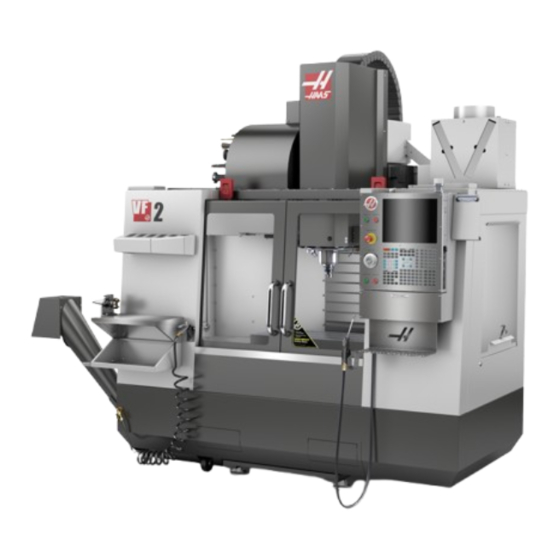
- Page 1 VMC Installation haascnc.com/service/troubleshooting-and-how-to/how-to/vmc-installation-guide.html Recently Updated LAST UPDATED: 07/22/2020 1/37...
- Page 2 Introduction This procedure will guide you through the installation of a VMC Tools required: Precision Machinist Level, 0.0005" Division Precision Spindle Test Bar, 8" Long 3/4 " socket and ratchet 1-1/2" Wrench Tape Measure 0.0005" or 1 micron indicator For 110V machines: 110V Electrical receptacle tester with GFCI diagnosis...
- Page 3 Leveling Screws Hardware Note: The washers [1] and nuts [2] are installed during shipping and should be saved for installation and not be discarded. Note: The washer orientation [3] is important. The conical part of the washer should be against the casting, see illustration.
- Page 4 Removal of Rust Inhibitor For ease of removal, first use a plastic scraper to remove most of the rust inhibitor and then use WD-40 or another PH neutral degreaser to spray all the way covers and other non-painted surfaces that have been coated with rust inhibitor.
-
Page 5: Air Connection
Air Connection Connect the air supply at the lube panel. Note: For air requirements refer to the decal that is located on the lube cabinet door. 5/37... -
Page 6: Electrical Connections
Electrical Connections 6/37... - Page 7 Danger: WORKING WITH ELECTRICAL SERVICES REQUIRED FOR A CNC ARE EXTREMELY HAZARDOUS. ALL POWER TO CNC MUST BE TURNED OFF LOCKOUT-TAGOUT AT THE SOURCE PRIOR TO CONNECTING THE LINE WIRES TO CNC. HOWEVER, IF THIS NOT THE CASE OR ARE NOT SURE HOW TO DO THIS, CHECK WITH APPROPIATE PERSONNEL OR OBTAIN THE NECESSARY HELP BEFORE CONTINUING.
- Page 8 1-Phase Machines: Insert each power lead into the wire cover. Connect the two power leads to L1 and L3 terminals on top of the main circuit breaker. 3-Phase Machines: Insert each power lead into the wire cover. Connect the three power leads to L1, L2 and L3 terminals on top of the main circuit breaker.
- Page 9 After the line voltage is connected to the machine, make sure that main circuit breaker (at top-right of rear cabinet) is OFF . Remove the Lockout / Tagout and Turn ON the power at the source. Using a digital voltmeter and appropriate safety procedures: 1-Phase Machines: Measure the AC voltage across L1 &...
- Page 10 Important: With the main circuit breaker turned OFF. Check the transformer taps at the bottom-right corner of the rear cabinet. 1-Phase Machines: The input voltage cable must be moved to the connector which corresponds to the average voltage measured in the above step. 3-Phase Machines: The input voltage cables labeled 74, 75, and 76 must be moved to the terminal block triple which corresponds to the average voltage measured in the above step.
- Page 11 Transformer T5 supplies 24VAC used to power the main contactor. There are two versions of this transformer for use on a 240 and 400V machines. The 240V transformer has two input connectors located about two inches from the transformer, which allow it to be connected to either 180-220V or 221-240V. Users that have 220V- 240V RMS input power should use the connector labeled 221-240V, while users with 190-220V input power should use the connector labeled 180-220V.
- Page 12 Apply power to the control by pressing the Power-On switch on the front panel. Check the DC Voltage and AC Line Voltage gauges in Diagnostics. The DC Voltage gauge must read between 310 - 360V. The AC Line Voltage must be between 90 and 105 percent. If the voltage is outside these limits, turn off the power and recheck steps 2 and 3.
- Page 13 When the machine is properly placed and connected to both air and electrical power, it is ready for final installation (removing shipping blocks, leveling, spindle sweep, etc.) and software activation. The HFO service technician does this. Contact the local HFO to schedule the work. 13/37...
- Page 14 Removal of Shipping Brackets 14/37...
- Page 15 Remove the zip tie holding the chip auger in place and remove the auger [1] Remove the cardboard tubing used to protect the auger. [2] Remove the bracket and cardboard protecting the cable guide on top of the machine [3,4] Note: For large VMCs There is no bracket removal needed only cardboard removal.
- Page 16 Remove the Shipping brackets keeping the doors in place. [5,6,7,8] Now that you have access, install the chip auger. For a guide on chip auger installation please see: VF 1-5 CHIP AUGER INSTALLATION 16/37...
- Page 17 Power up the machine and jog the Z-axis upward Remove the spindle bracket. [9] 17/37...
- Page 18 Additional option brackets If you purchased a machine with the Wireless Intuitive Probing System (WIPS) remove the bracket attached to the table [10] If you purchased a machine with a Multi-Auger Chip Conveyor Remove the Shipping brackets holding it in a its vertical position [11] 18/37...
-
Page 19: Machine Leveling
Machine Leveling 19/37... - Page 20 Adjust the four corner leveling screws to the same height to lift the base casting 3-1/2" from the ground. Loosen the middle leveling screws [3, 6] so that they are not touching the pads, install jam nuts [1] on leveling screws, but do not tighten Jog the table so that it is centered in the machine.
- Page 21 3 and 6 The Tolerance for both the twist and bow is N.T.E 0.0002"/10" For a more in depth guide on how to level your VMC including how to level machines with outriggers please see:...
- Page 22 Spindle Sweep 22/37...
- Page 23 Tools Required: Test Indicator with a magnetic mount. pH-neutral cleaner Degreaser Abrasive pad Gauge Block (optional) Clean the table surface to remove any corrosion Jog the spindle down to the middle of the z-axis travel and attach the magnetic base to the spindle Adjust the indicator to measure a 10"...
- Page 24 If the spindle sweep values come back into tolerance with only small adjustments to the leveling screws then there is no need to recheck the twist and bow. For a more in depth guide on how to perform a spindle sweep test on your VMC please see: VMC SPINDLE SWEEP...
- Page 25 Lubrication Verification Run the spindle run-in program. Examine the sight glass, make sure the correct number of drops are fall through the sight glass. Examine the fittings [1,2] on top of the oil pump tank. The oil collects on top of the oil pump tank [3] either behind or in front of the sight glass bracket, underneath the leaking fitting.
-
Page 26: Pendant Installation
Pendant Installation After removing the pendant from its packaging you can now install it on your machine. For a pendant installation guide please see: VMC PENDANT INSTALLATION 26/37... - Page 27 Option Installation Guides Verify and test that all the options have been properly installed. REMOTE JOG HANDLE (RJH-TOUCH) - INSTALLATION WI-FI CAMERA OPTION INSTALLATION VMC CONVENIENCE PACKAGE AUXILARY COOLANT FILTER CABCOOL INSTALLATION PULSEJET INSTALLATION HAAS OIL SKIMMER TABLE WORK LIGHT...
-
Page 28: Machine Operation
Machine Operation 28/37... - Page 29 Test Spindle Operation Run Spindle Run in program 009221 located in the 009000 folder. In the case of unusual spindle noise run a vibration test For a guide on how to perform a spindle vibration test please see: VIBRATION ANALYSIS - ETHERNET INTERFACE VIBRATION ANALYSIS - RS-232 INTERFACE 29/37...
- Page 30 Test Coolant Operation Connect the Coolant pump and if your machine is came with the TSC option also connect the TSC pump Test the flood coolant operation by pressing the [Coolant] button on the control [1] For TSC machines test the TSC coolant operation by pressing the [AUX CLNT] button on the control 30/37...
- Page 31 Test Chip Auger Operation Test the chip auger by cycling between the [CHIP FWD], [CHIP STOP], and [CHIP REV] buttons 31/37...
- Page 32 Test Remote Jog Handle (RJH-Touch) If your machine came with the remote jog handle option: Attach the holster to the machine using the provided hardware Hang RJH on holster On the Control Pendant, press [MDI] and then [HAND JOG]. (Image 2) Verify that the jog wheel on the Control Pendant works properly while RJH is docked Remove RJH HAND UNIT from the holster.
- Page 33 While the locks are on try to open the doors The spindle should not stop rotating but if the spindle stops, contact Haas for support Test Through Spindle Air Blast (TAB) If your machine came with the TAB option:...
- Page 34 Test Auto Air Gun (AAG) If your machine came with the AAG option: Press [MDI] and type M83; and press [Enter] Press [CYCLE START] Check AAG for proper function, check solenoid for leaks in the CALM cabinet. In [MDI] type M84; then press [CYCLE START] to de-activate the AAG. 34/37...
- Page 35 Try to pull door open, The door gap is not to exceed 0.25”. If the machine alarms out, does not close properly, closes hard, or the door gap exceeds 0.25" contact Haas for support Z-axis tool change offset parameter For a guide on how to check the Z-axis tool change offset parameter for either side mount tool changers or...
- Page 36 WIPS Calibration If your machine includes the WIPS option perform the calibration procedure For a guide on how to perform the WIPS calibration procedure please see: WIPS CALIBRATION NGC 36/37...
- Page 37 Test Safety Features Turn the (Run / Set-up) key switch to the Set-up mode Test Memory Lock switch by verifying that in the ON position changes cannot be made to settings or programs. Press [MDI] and type M03 S500; Open door. Press [CYCLE START] the spindle should not start. Close door.
Need help?
Do you have a question about the VMC and is the answer not in the manual?
Questions and answers