Rugged Radios G4 User Manual
Hide thumbs
Also See for G4:
- Installation instructions manual (8 pages) ,
- Installation instructions manual (8 pages) ,
- Quick start manual (2 pages)
Table of Contents
Advertisement
Quick Links
Advertisement
Table of Contents
Troubleshooting

Related Manuals for Rugged Radios G4


Summary of Contents for Rugged Radios G4
- Page 1 USER MANUAL V1.0 | 11/24...
- Page 2 Communications Commission (FCC) license. You must be licensed prior to operating on channels 1-7, 15-22 or RP15-22 which comprise the GMRS channels of the G4. Serious penalties may result from unlicensed use of GMRS channels, in violation of FCC rules, as stipulated in the Communications Act’s Sections 501 and 502 (amended). You will be issued a call sign by the FCC that should be used for station identification when operating your radio on GMRS channels.
- Page 3 FCC RF Exposure and Separation Distance: This radio transmitter has been approved by FCC to operate with the antenna types listed below with the maximum permissible gain and required antenna impedance for each antenna type indicated. Antenna types not included in this list, having a gain greater than the maximum gain indicated for that type, are strictly prohibited for use with this device.
-
Page 4: Table Of Contents
CONTENTS User Safety Information GMRS Repeater Channels Package Includes Specifications Main Features General Installation Receiver Mobile Installation Transmitter Notes DC Power Cable Connection Replacing Fuses Accessory Connections External Speaker Antenna and Cable Installing the Antenna Getting Acquainted Front Panel Operation Rear Panel Operation Hand Mic Operation Menu... -
Page 5: User Safety Information
USER SAFETY INFORMATION • Do not attempt to configure your radio while driving. • This radio is designed for a 12 Volt DC power supply. Do not use a 24 Volt battery to power this radio. • Keep this radio away from devices that cause interference, such as TV’s, Generators, etc. -
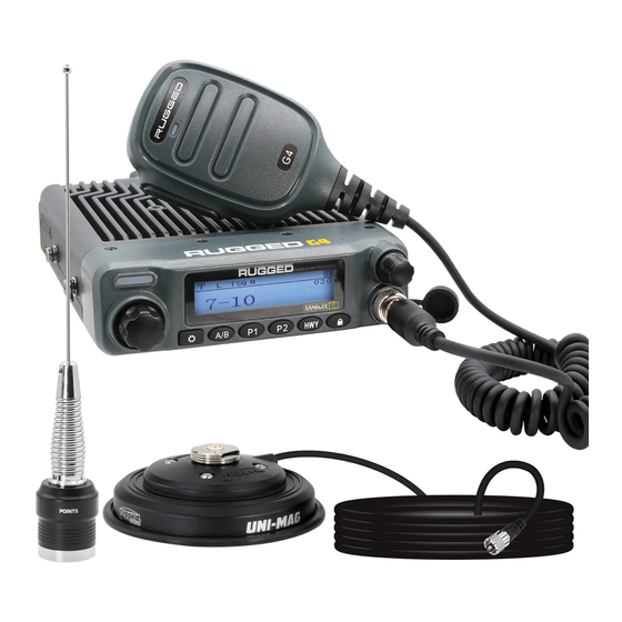
Page 6: Package Includes
PACKAGE INCLUDES • Radio Unit x 1 • Hand Mic x 1 • Magnetic Hand Mic Mount x 1 • Mobile Mounting U-Bracket x 1 • DC Power Cable with Fuse Holder x 1 • Mounting Screws x 4 • Protection Fuses x 1 •... -
Page 7: Main Features
INTRODUCTION From the trails of Moab to the deserts of the Baja Peninsula, the Rambler G4 is ready to Go Further! The large, clear, easy-to-read display provides quick access to programmable controls with an intuitive user interface. With over 40 watts of power, the Rambler G4 is ready to go the distance. -
Page 8: Installation
INSTALLATION MOBILE INSTALLATION Mobile Installation: Select a location that is safe and easy to reach to protect you and your passengers while the vehicle is in motion. Consider installing the radio in a location and position in which knees and legs will not strike it during sudden braking. Choose a well- ventilated location that is shielded from direct sunlight and heat sources. -
Page 9: Dc Power Cable Connection
INSTALLATION DC POWER CABLE CONNECTION This radio is designed to operate on 12 Volt systems. Never connect to a 24 Volt system without reducing to 12 Volts. If the power supply is lower than 12 Volts, the display may darken during transmissions, transmit power may decrease dramatically, and/or the radio may reboot. -
Page 10: Replacing Fuses
If a fuse blows, determine the cause and correct the problem. After the problem is resolved replace the fuse. If newly installed fuses continue to blow, disconnect the power cable and contact Rugged Radios for assistance. Only use fuses of the specified type and rating are suitable for use otherwise the radio could be damaged. -
Page 11: Accessory Connections
ACCESSORY CONNECTIONS EXTERNAL SPEAKERS Use the External Speaker Connection on the back of the radio to connect your external speaker device. •If you plan to use an external speaker, choose a speaker with an impedance of 8 ohms. • The external speaker jack accepts a 3.5mm mono (2-conductor) plug. -
Page 12: Antenna And Cable
ANTENNA AND CABLE Radio Antenna is an optional additional purchase. Please visit our website for a list of compatible antenna. Radio performance relies greatly on the antenna and antenna cable! Before operating, install an efficient, well-tuned antenna and a high-quality antenna cable. Failure to do so will reduce transmit and receive range, radio call clarity, and can damage the radio. -
Page 13: Installing The Antenna
NOTE: proper antenna mounting, the radio range and quality may decrease. For the best range, only the Rugged Radios GMRS POINT5 antenna should be used. Specific installation requirements vary between vehicles. Use the following guidelines to install the antenna. The location of your antenna will significantly effect your radio’s performance! Mount the antenna as high on the vehicle as possible. -
Page 14: Getting Acquainted
GETTING ACQUAINTED FRONT PANEL OPERATION Function Quick-Press Long-Press Indicator Illuminates red while Light transmitting. Volume Knob Powers the radio on/ off, adjusts volume Channel Changes channels / Knob scrolls through menu Enters the menu / Menu/ confirms the current Confirm selection Switches between Programmable... - Page 15 FRONT PANEL OPERATION CONTINUED Function Quick-Press Long-Press Quick access to P1 Preset Ch. 15 Saves current channel preset channel to P1 Quick access to P2 Preset Ch. 16 Saves current channel preset channel to P2 Quick access to Preset Ch. 19 Programmable Highway Channel 19 Locks the radio controls...
-
Page 16: Rear Panel Operation
GETTING ACQUAINTED REAR PANEL OPERATION Port Function Intercom Connector Rugged Ready connector used for headsets, intercoms, etc. Requires adapter cable PN CJ-M1. External Speaker Mono (2-conductor) audio connector for external speakers. Power Cable Connects to the radio power cable. Ensure a direct connection to the battery to avoid electrical interference. -
Page 17: Hand Mic Operation
GETTING ACQUAINTED HAND MIC OPERATION Function PTT Button To transmit, hold microphone approximately 4 “Push-To-Talk” inches from mouth, press the key [1], and speak into microphone. Release PTT key [1] when transmit is complete. -
Page 18: Menu
Tone Codes Increases or decreases the sensitivity of the receiver. Higher Squelch settings will block more interference but also limit range. Note: Rugged Radios suggests using the Squelch factory-set Squelch level, but if adjustments are made as a general rule, lower, more sensitive settings are suggested. - Page 19 GETTING ACQUAINTED MENU Menu Item Operation Audibly announces the channel frequency or name. CH Announce Sets the length of time before the menu times out and Menu Timeout returns to default display. Enables automatic keypad locking feature after the Autolock selected duration.
-
Page 20: Advanced Menu
GETTING ACQUAINTED ADVANCED MENU Menu Item Operation The level of power output used during transmission. Tx Power (High/Medium/Low) Changes operating bandwidth. Bandwidth Wide (25 kHz) or Narrow (12.5kHz) When monitoring two channels (dual monitor), B Channel B CH Alert Alert emits a tone when radio calls are received on “B” or “Sub”... -
Page 21: Troubleshooting
TONE CODES Along with the standard GMRS channels, all Rugged GMRS radios come preprogrammed with two “tone coded” channel options. Example: • Channel 1 is GMRS 1, with Frequency of 462.5625 MHz • Channel 1-10 is GMRS 1, with Frequency of 462.5625 MHz, and Tone Code 94.8 (10) •... -
Page 22: Changing Tone Codes
See the lists of Tone Codes below: GMRS TONE CODES CTCSS Analog Tone Codes This is the Freq. Freq. (Hz) (Hz) number you toggle to on 67.0 167.9 71.9 173.8 your r adio! 74.4 179.9 77.0 186.2 79.7 192.8 82.5 203.5 85.4 210.7... -
Page 23: Dcs
GMRS TONE CODES DCS Digital Tone Codes DCS (Digital) DCS (Digital) DCS (Digital) DCS (Digital) Code Code Code Code Codes 84-104 may not be supported by other br and GMRS r adios To toggle between numbered tone codes [EX: 22] and actual tone codes [EX:141.3], press [ ] when in tone code menu Only radios produced after March 1, 2022 (signified by a waterproof power connector) are equipped with this feature. -
Page 26: Troubleshooting
TROUBLESHOOTING Problem Possible Cause and Potential Solutions + and - polarities of power connection are reversed. (a) Power is on, nothing appears Connect red lead to plus terminal and black lead to on Display. minus terminal of DC power supply. Check and solve problem resulting in blown fuse (b) Fuse is blown. -
Page 27: Specifications
SPECIFICATIONS GENERAL Frequency Range TX-462-467MHz RX: 400-480MHz Channel Capacity Frequency Stability ±2ppm Working Temperature -30°C ~ +60°C Working Voltage 13.8V DC Dimension(HxWxD) 53*138*153mm Weight 2.55 lbs. Standard U-Bracket Mount Screws M4-0.7x8mm AMPS Mounting Screws (Flange) M4-0.7x8mm or 16mm AMPS Mounting Screws M6-0.7x8mm... -
Page 28: Receiver
SPECIFICATIONS RECEIVER Receiving Sensitivity 0.25μV @ 12dB SINAD Adjacent Channel Selectivity ≤-60dB@12.5KHz Inter-modulation ≥60dB Spurious Rejection ≥70dB Audio response +1~-3dB Audio Distortion <5% Audio power ≤3W Hum/Noise ≥40dB@25KHz /≥35dB @12.5KHz Standby current 0.16A RX current 0.4A... -
Page 29: Transmitter
SPECIFICATIONS TRANSMITTER Output Power High:40W Middle:25W Low:5W TX Current ≤9A 11K0F3E @ 12.5KHz 14K0F3E @ 20KHz FM Modulation 16K0F3E @ 25KHz Modulation Distortion <5% Hum/Noise ≥40dB@25KHz /≥35dB@12.5KHz Adjacent Channel Power ≤-60dB@12.5KHz Audio Response +1~-3dB Spurious ≤-30dBm12.5kHZ data and audio:7K60FXE... -
Page 30: Notes
NOTES... - Page 31 WWW.RUGGEDRADIOS.COM...
Need help?
Do you have a question about the G4 and is the answer not in the manual?
Questions and answers