Renogy RIV1210PU-126 / RlV1220PU-126 / RlV1230PU-126 Manual
- User manual (32 pages)
Advertisement
- 1 Symbols Used
- 2 Introduction
- 3 Key Features
- 4 SKU
- 5 What's In the Box
- 6 Required Tools & Accessories
- 7 Get to Know Your Product
- 8 Part Description
- 9 How to Properly Install Cable Clamps
- 10 System Setup
- 11 Size a Battery Bank
- 12 Wear Insulating Gloves
- 13 Plan a Mounting Site
- 14 Grounding
- 15 DC Wiring
- 16 AC Output Wiring
- 17 AC Input Wiring
- 18 Power On/Off
- 19 N-G Bonding Relay
- 20 Monitor the Unit
- 21 LED Overview & Troubleshooting
- 22 Pure Sine Wave
- 23 Specifications
- 24 General Safety Information
- 25 Renogy Support
- 26 Documents / Resources
Symbols Used
The following symbols are used throughout the user manual to highlight important information.
 WARNING: Indicates a potentially dangerous condition which could result in injury or death.
 CAUTION: Indicates a critical procedure for safe and proper installation and operation.
 NOTE: Indicates an important step or tip for optimal performance.
Introduction
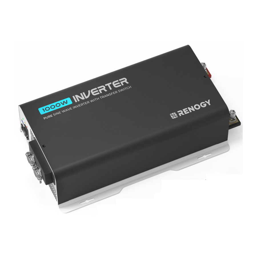
Renogy 12V 1000W/2000W/3000W Pure Sine Wave Inverter with Transfer Switch is ideal for a wide range of off-grid applications, including vans, semi-trucks, fifth wheels, cabins, and remote locations that require reliable power sources. The inverter converts DC Power stored in batteries into usable AC Power for appliances. Renogy's advanced pure sine wave technology empowers you to run a wide variety of AC appliances without the risk of damaging even your most sensitive equipment.
Key Features
- Powerful DC-AC Conversion
Continuous rated output power with a conversion efficiency greater than 92%, and up to 2x surge for start-up loads. - Uninterrupted Power Supply (UPS)
Utilizing the built-in transfer switch, this inverter seamlessly switches to grid power, bypassing the inverter when it's available, thereby directly supplying the load with grid power. - Safe for Use
The inverter provides multiple protection mechanism such as overload, overtemperature, overvoltage, short-circuit, and undervoltage protections as well as an integrated Ground Fault Circuit Interrupter (GFCI). - Guaranteed Appliance Protection
Our pure sine wave technology ensures appliance longevity by delivering a clean sine wave that's comparable to or even better than grid power. Say goodbye to annoying buzzing sounds and enjoy the smooth operation of all your devices. - Easy to Use
Offers a built-in 5V/2.1A USB port, AC Outlets, Hardwired AC Output Terminal Block, and a Wired Remote Port. - Dependable Quality
The inverter is UL certified to 458, CSA 22.2 No. 107.1-01, and FCC Part 15 Class B standards, ensuring reliability and safety for all users.
SKU
| Renogy 12V 1000WPure Sine Wave Inverter with Transfer Switch | RIV1210PU-126 |
| Renogy 12V 2000W Pure Sine Wave Inverter with Transfer Switch | RIV1220PU-126 |
| Renogy 12V 3000W Pure Sine Wave Inverter with Transfer Switch | RIV1230PU-126 |
What's In the Box

Make sure that all accessories are complete and free of any signs of damage.
The accessories and product manual listed are crucial for the installation, excluding warranty information and any additional items. Please note that the package contents may vary depending on the specific product model.
The 1000W inverter comes with 4 AWG Cables. The 2000W inverter comes with 1/0 AWG Cables. The 3000W inverter does not include cables, so you will need to prepare them yourself. We recommend using 3/8in Lugs (M12 Ring Terminals) and 2/0 AWG Cables.
Required Tools & Accessories
Choose proper mounting screws specific to your installation site. This manual takes self-tapping screws for wooden walls as an example.

Prior to installing and configuring the inverter, prepare the recommended tools, components, and accessories.
Get to Know Your Product
Renogy 12V 1000W
- AC Side View

- DC Side View

- Dimensions


Dimension tolerance: ±0.2 in (0.5 mm)
Renogy 12V 2000W
- AC Side View

- DC Side View

- Dimensions


Dimension tolerance: ±0.2 in (0.5 mm)
Renogy 12V 3000W
- AC Side View

- DC Side View

- Dimensions


Dimension tolerance: ±0.2 in (0.5 mm)
Part Description


How to Properly Install Cable Clamps
The AC Input Terminals and AC Output Terminals are equipped with cable clamps to ensure that the wiring connections remain secure and do not come loose due to vibrations.
- Remove the two screws on the protective cover to access the terminals.
- Loosen the screws on a cable clamp with a Phillips Screwdriver.
- Lift the clamp, and run the cables through the clamp.
- Secure the clamp by fastening the screws.
- Install the protective cover and secure it using two screws.
System Setup
System Wiring

The wiring diagram only shows the key components in a typical DC-coupled off-grid energy storage system for the illustrative purpose. The wiring might be different depending on the system configuration. Additional safety devices, including disconnect switches, emergency stops, and rapid shutdown devices, might be required. Wire the system in accordance with the regulations at the installation site.
The grid supplies the connected loads only. It does not charge the battery.
Unit Wiring
The wiring diagram provided in this section is tailored for a 1000W inverter model. Similar wiring rules apply to other models.
- AC Side View

- DC Side View


Size a Battery Bank
Battery types and capacity relate to the overall inverter performance. To size a proper battery bank, you need to identify the loads that you will be utilizing, as well as an estimate duration (hours/day) you will be using the load. The inverter is only compatible with 12V battery banks, and oversizing should be considered due to efficiency losses.
- Determine Your Watts (Amps x Volts)
Every electronic device will have a sticker or plate identifying the watts directly (W) or will show you the voltage value (V) as well as amperage (A) which need to be multiplied to get Watts. The formula is below:
Watts (W) = Volts (V) x Amps (A)
Example: Fan Watts = 120V * 0.4A = 48Watts - Estimate Load Run-Time in Watt-Hours (Wh)
Estimate how many hours per day you will be using the load and multiply this by your Watts per load.
Example: Fan Watts x 12 hours = Watt-Hour (Wh)
48W x 12h = 576Wh - Determine Battery Capacity in Amp-Hour (Ah)
Divide your Load Run Watt-Hour result by the battery voltage.
Load Run-Time (Wh)/Battery Voltage (V) = Amp-Hour (Ah)
Use 12V, supported voltage of the inverter as a reference.
576Wh/12V = 48 Ah - Oversize the Battery
The calculated Amp-Hour value represents the minimum size battery capacity to run your load for your intended time. Note that this assumes 100% use of a battery, which is not recommended. Assuming 50% depth of discharge, you want to multiply this value by 2 and you also want to multiply by 1.25 to account for some efficiency losses.
Formula:
48Ah x Oversize x Efficiency Losses = Recommended Amp-Hour
48 x 2 x 1.25 = 115Ah
Therefore, a 115Ah battery bank, or close, will be able to support a 12-hour run time while also prolonging battery life for the best system size possible.
Actual battery quantities vary by battery capacity and rates of discharge.
Wear Insulating Gloves
This manual utilizes the 1000W Inverter as a reference for its illustrations. The wiring techniques remain consistent across all inverter models, though there may be variations in terminal positions.

Plan a Mounting Site
Follow the guidelines below:
- Cool, dry, and well-ventilated area
The inverter must be installed in a site where the fans are not blocked or where they are not hit directly by the sun. The site should be free of any kind of moisture with a clearance of at least 10 inches around the inverter for adequate ventilation. - Protection against fire hazard
The inverter should be away from any flammable material, liquids, or any other combustible material. - Close proximity to battery bank
Put the inverter close to batteries banks to prevent excessive voltage drop. Choose a proper sized wire going from the battery bank to the inverter. - Limiting electromagnetic interference (EMI)
Ensure the inverter is firmly grounded to a building or vehicle. Alternatively, it can be earth grounded. Keep the inverter away from EMI receptors such as TVs, radios, and other audio/ visual electronics to prevent damage/interference. - Secure mounting
The inverter should be stand-alone or mounted by using the outlying terminals with ST4 and ST6 screws on the inverter.


Do not over-torque or overtighten the terminals. This could potentially damage the unit.
Refer to the technical specifications for maximum wire sizes on the controller and for the maximum amperage going through wires.
Ensure the inverter is in the OFF position before connecting to anything.
Do not install the inverter in the same compartment as the battery bank because it could serve as a potential fire hazard.
Never mount the inverter vertically on a vertical surface since it would present a hazard for the fan opening, undermining cooling the inverter.
How to Properly Install Cable Clamps?
The AC Output Port with cable clamps to ensure that the wiring connections remain secure and do not come loose due to vibrations.
- Loosen the screws on a cable clamp with a Phillips Screwdriver.
- Lift the clamp, and run the cables through the clamp.
(You will need 1 x 3 prong (10 AWG recommended Black, White, Green) ac cables not provided with this product. Measure the required length for your particular application. for ac output of the inverter. SJT0 and SJT,SJ0 are recommended wire) - Secure the clamp by fastening the screws
Do not use the bare wires if there is any visible damage.
Do not use SP-3, SPT-3 type wire
The screw torque of a cable clamp is 14.16 in.lbs (1.6 N.m). Do not over tighten the screws to prevent damage
Grounding
Grounding is highly recommended for both when using the inverter in a mobile application, such as an RV, or in a building. If available, the chassis ground lug should be connected to a ground point such as a vehicle chassis or boat grounding system. In fixed locations, connect the ground lug to earth ground. The connections to ground must be tight and against bare metal.

| Model | Recommended Size |
| 1000W Pure Sine Wave Inverter | 14 AWG |
| 2000W Pure Sine Wave Inverter | 12 AWG |
| 3000W Pure Sine Wave Inverter | 10 AWG |
When the GFCI fails to operate normally after grounding the inverter, please refer to "N-G Bondinq Relay" for details.

DC Wiring
The inverter is suitable for 12V battery bank systems ONLY. Not following the minimum DC requirement will cause irreversible damage to the device.
The input terminals of the inverters are embedded with large capacitors. The input circuit is completed once the terminals are connected to both positive and negative wires. This commences drawing a heavy current momentarily. As a result, there may be a sparking occurring even if the inverter is in the off position. To minimize sparking, it is recommended that you should choose an appropriate sized wire feeding into the inverters and/or install an external fuse leading into the inverter.
Be careful of the positive and negative poles. Reversing the poles might cause permanent damage to the inverter and will void the warranty.
For your safety, it is recommended that you should use a battery fuse on the positive end.
| Model | RIV1210PU-126 | RIV1220PU-126 | RIV1230PU-126 |
| Continuous Output Power | 1000W | 2000W | 3000W |
| Battery Fuse | 150A | 250A | 400A |
- On the AC side, set the ON/OFF Switch to the OFF position.

- On the DC side, remove the protection caps.

- Unscrew Positive and Negative DC Input Terminals, connect a battery bank to the terminals, and tight the terminal screws. Torque: 14(± 0.5) N•m


AC Output Wiring
Recommended Ground-Fault Circuit Interrupter
A ground-fault circuit interrupter, or GFCI, is a device that helps protect people from electric shocks by de-energizing a circuit or portion of a circuit within an established period of time when a current to ground exceeds some predetermined value that is less than that required to operate the overcurrent device (circuit breaker or fuse) of the supply circuit. GFCIs are usually required in wet or damp locations.
While the inverter is equipped with a GFCI, an external GFCI is strongly recommended to elevate system safety.
The following table lists GFCIs that meet the specifications and will function properly when they are connected to the AC Outlets of the inverter.
| Tested GFCI Models | |
| Manufacturer | Model Number |
| Leviton | GFNT2 |
| Hubbell | GFP1305 |
| Hubbell | GF15WLA |
Risk of electrical shock. Use only ground-fault circuit interrupters [receptacle(s) or circuit breaker(s)] compatible with your inverter.
GFCIs shall be installed in a recreational vehicle's wiring system to protect all branch circuits.
AC Outlets
You can plug your AC loads directly into the AC Outlets on the inverter's AC side.
High Output AC Terminals
Additionally, you have the option to establish a permanent connection from the AC output by linking it through the High Output AC Terminals to a GFCI, a load sub-panel, or supplementary AC outlets that receive power from the inverter.
From left to right, the terminal block indicates: Ground (G), Live/ Hot (L), and Neutral (N).

For details on how to connect loads and the inverter to the GFCI, read the user manual of the specific GFCI.
AC Input Wiring
(Optional)
Utilizing the built-in transfer switch, this inverter seamlessly switches to grid power, bypassing the inverter when it's available, thereby directly supplying the load with grid power.
From left to right, the terminal block indicates: Live/Hot (L), Neutral (N), and Ground (G).

Risk of electric shock! Ensure the grid or the AC generator is turned off before connecting them to the inverter.
Power On/Off
Operations on the Unit
After proper battery and AC load connections, you can operate the inverter.
- On the AC side, rock the ON/OFF Switch to the ON position.
- The inverter is operating normally.
When finishing using the inverter, power off the AC loads first, and then rock the ON/OFF Switch to the OFF position.
When the inverter turns on, it is normal to see the fans run for a second and hear a beep.
Avoid powering on the inverter with the load (electronic devices) already switched on. This may trigger an overload since some electronic devices have an initial high power surge to start.
When switching off the inverter, turn off the electronic devices first. Although the inverter is off, the terminal capacitors will still have a charge, so the DC and AC terminals must be disconnected if altering the circuitry.
Wired Remote Control
The Wired Remote Control gives you the opportunity to power on/off the inverter from a distance (approximately 16.4 ft / 5 m).
Note that the inverter ON/OFF switch should be in the REM position.
- Connect the Wired Remote Control to the inverter via the Remote Control Connector.

- Rock the ON/OFF Switch to the REM position, and you can power on/off the inverter via the Wired Remote Control.


N-G Bonding Relay
The inverter is equipped with a Neutral to Ground (N-G) bonding relay that ensures that either the neutral in or out contact of the RV is always grounded.
This helps prevent electrical shock caused by contact between the neutral contacts of the RV and external AC power sources.
By default, the Neutral to Ground bonding relay is enabled when the inverter is shipped from the factory.
- When there is AC input current, the N-G bonding relay automatically opens the neutral-to-ground connection as shown in the figure below, and the system connects to the grid ground contact.

- When there is no AC input current, the N-G bonding relay automatically closes and connects to the ground contact of the inverter. In this case, the inverter supplies loads with the connected battery.


In scenarios where the N-G bonding relay is disabled, the N-G bonding relay connects to the ground contact of the inverter only.
You have the option to manually enable or disable the N-G Bonding Relay.

The N-G bonding relay must be enabled when the battery supplies the connected loads because the GFCI will be unavailable if the N-G bonding relay is disabled.
In scenarios when N-G bonding relay is disabled, the inverter must be grounded.
Monitor the Unit
Depending on the specific application, the inverter can establish either short-range or long-range communication connections with monitoring devices. These monitoring devices facilitate real-time monitoring, programming, and complete system management, offering comprehensive control and enhanced flexibility.
The version of the DC Home app might have been updated. Illustrations in the user manual are for reference only. Follow the instructions based on the current app version.
Make sure that the inverter is properly installed and powered on before it is paired with the DC Home app.
To ensure optimal system performance, keep the phone within 10 feet (3 m) of the inverter.
Download the DC Home app. Login to the app with your account.


Short-Range Monitoring via DC Home App

If only short-range monitoring is required, connect the inverter to the DC Home app directly through the Bluetooth of your phone.
Wireless Long-Range Monitoring

If long-range communication and programming are required, connect the inverter to Renogy ONE (sold separately) through Bluetooth, and the Renogy ONE to the DC Home app through Wi-Fi.

Components marked with "*" are available on renogy.com.
For instructions on Renogy ONE, see Renoqy ONE Core User Manual and Renoqy ONE M1 User Manual.
LED Overview & Troubleshooting
| LED Status | Alarm | Protection & Alarm | Inverter Status |
LED in flicker red | Alarm beeps | Input voltage is below 11V. | Keep input voltage above IIV. |
| Input voltage is above 15.5V. | Keep input voltage below 15.5V. | ||
Power LED in solid green | No sound | Recovery from undervoltage | Normal output from the inverter. |
GFCI LED in solid yellow | Long steady beeping sound | GFCI protection |
|
No sound and the unit is off | GFCI tripped | Disconnect appliances, and use the ON/OFF/Remote switch to reset the inverter. | |
Fault LED in solid red | Long steady beeping sound | Overtemperature protection |
|
| Undervoltage shutdown | No output from the inverter. Keep input voltage above 10.5V. | ||
| Short circuit protection | No output from the inverter. After 5s, the inverter automatically restarts. After five times of failed restart, the inverter needs to be restored by manually turning it on. | ||
| Overvoltage protection | No output from the inverter. Keep input voltage below 16V. | ||
| Overload protection | Automated recovery after 20 seconds (manual restart required if automated recovery fails). |
For further assistance, contact Renogy technical support service at https://www.renoqy.com/contact-us.
Pure Sine Wave
The inverter outputs a pure sine wave similar to the waveform of the grid power. In a pure sine wave, the voltage rises and falls in a smooth fashion with very low harmonic distortion and cleaner utility-like power.
This technology allows the inverter to supply electronic devices that require a high quality waveform with little harmonic distortion. In addition, the technology enables the inverter to be more efficient than traditional ones, allowing you to use less energy to supply more devices. The inverter can provide sufficient, stable power for tools, fans, lights, computers, and other electronics without any interference.

Specifications


General Safety Information

- Have the inverter installed by a qualified technician in accordance with the local and national electric codes (NEC).
- There are no serviceable parts for this inverter. Do not disassemble or attempt to repair the inverter.
- Ensure all connections going into and from the inverter are tight. There may be sparks when making connections; therefore, there should not be flammable materials or gases near the installation site.
- The inverters are suitable for 12V battery banks ONLY.
- Always ensure the inverter is in OFF position and disconnect all AC and DC devices associated with the inverter.
- Never connect the AC output of the inverter directly to an Electrical Breaker Panel or Load Center which is also fed from the utility power or generator.
- Please confirm the polarity of the devices before connection. A reverse polarity contact can cause injury and damage the device.
- Be careful when touching bare terminals of capacitors as they may retain high lethal voltages even after power is removed.
- Do not let the positive (+) and negative (-) terminals of the battery touch each other. Use only deep-cycle sealed lead-acid, flooded, gel, or lithium batteries.
- Risk of explosion! Never install the inverter in a sealed enclosure with flooded batteries! Do not install in a confined area where battery gases can accumulate.
- Be careful when working with large lead acid batteries. Wear eye protection and have fresh water available in case there is contact with the battery acid.
- Overcharging and excessive gas precipitation may damage the battery plates and activate material shedding on them. Too high of an equalizing charge or too long of one may cause damage. Carefully review the requirements of the specific battery in use.

- Install the inverter in a well-ventilated, cool, and dry environment. Make sure the fans of the inverter and the ventilation holes are not blocked.
- Do not expose the unit to rain, moisture, snow, or liquids of any type.
Renogy Support
To discuss inaccuracies or omissions in this quick guide or user manual, visit or contact us at:
renogy.com/support/downloads contentservice@renogy.com

Questionnaire Investigation
To explore more possibilities of solar systems, visit Renogy Learning Center at:
renogy.com/learning-center
For technical questions about your product in the U.S., contact the Renogy technical support team through:
renogy.com/contact-us 1(909)2877111
For technical support outside the U.S.,visit the local website below:
| Canada | ca.renogy.com | China | www.renogy.cn |
| Australia | au.renogy.com | Japan | jp.renogy.com |
| Other Europe | eu.renogy.com | Germany | de.renogy.com |
| United Kingdom | uk.renogy.com |
Renogy Empowered
Renogy aims to empower people around the world through education and distribution of DIY-friendly renewable energy solutions.
We intend to be a driving force for sustainable living and energy independence.
In support of this effort, our range of solar products makes it possible for you to minimize your carbon footprint by reducing the need for grid power.
Live Sustainably with Renogy
Did you know? In a given month, a 1 kW solar energy system will...
Save 170 pounds of coal from being burned
Save 300 pounds of CO2 from being released into the atmosphere
Save 105 gallons of water from being consumed
Renogy Power PLUS
Renogy Power Plus allows you to stay in the loop with upcoming solar energy innovations, share your experiences with your solar energy journey, and connect with like-minded people who are changing the world in the Renogy Power Plus community.

@Renogy Solar

@renogyofficial

@Renogy
Documents / Resources
References
RENOGY如果新能源 | 让每个人拥有独立清洁的能源
![play.google.com]() Google Play
Google Play![www.apple.com]() App Store - Apple
App Store - Apple![renogy.com]() Renogy US Official | Trusted Energy Solutions
Renogy US Official | Trusted Energy Solutions![renogy.com]() Downloads
Downloads![renogy.com]() Renogy Learning Center
Renogy Learning Center![renogy.com]() Contact Us | Renogy Solar Panels and Complete Solar Kits
Contact Us | Renogy Solar Panels and Complete Solar Kits![ca.renogy.com]() Renogy CA Official | Trusted Energy Solutions
Renogy CA Official | Trusted Energy Solutions![au.renogy.com]() Renogy AU Official | Trusted Energy Solutions
Renogy AU Official | Trusted Energy Solutions![jp.renogy.com]() Renogy JP 公式サイト| 信頼のエネルギーソリューション
Renogy JP 公式サイト| 信頼のエネルギーソリューション![eu.renogy.com]() Renogy EU Official | Trusted Energy Solutions
Renogy EU Official | Trusted Energy Solutions![de.renogy.com]() Renogy DE Official | Trusted Energy Solutions
Renogy DE Official | Trusted Energy Solutions![uk.renogy.com]() Renogy UK Official | Trusted Energy Solutions
Renogy UK Official | Trusted Energy Solutions
Download manual
Here you can download full pdf version of manual, it may contain additional safety instructions, warranty information, FCC rules, etc.
Download Renogy RIV1210PU-126 / RlV1220PU-126 / RlV1230PU-126 Manual
Advertisement


Need help?
Do you have a question about the RIV1210PU-126 and is the answer not in the manual?
Questions and answers