Advertisement
- 1 DC Home App
- 2 General Information
- 3 Get to Know Your Product
- 4 Preparation
- 5 Installation
- 6 LED Indicators
- 7 Configuration
- 8 Monitoring
- 9 Working & Charging Logic
- 10 Fault Indicator Errors
- 11 Built-in Protection Mechanisms
- 12 Dimensions & Specifications
- 13 Maintenance
- 14 Emergency Responses
- 15 Renogy Support
- 16 Documents / Resources
DC Home App


General Information
Symbols Used
The following symbols are used throughout the user manual to highlight important information.
 WARNING: Indicates a potentially hazardous condition that could result in personal injury or death.
 CAUTION: Indicates a critical procedure for safe and proper installation and operation.
 NOTE: Indicates an important step or tip for optimal performance.
Introduction
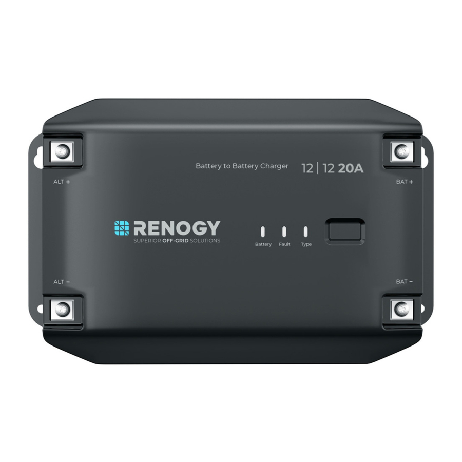
Renogy 12V 20A/40A DC-DC Battery Charger allows you to charge your 12V auxiliary battery from the starter battery in your RV. The supported auxiliary battery types include deep-cycle gel-sealed leadacid batteries (GEL), flooded lead-acid batteries (FLD), sealed lead-acid batteries (SLD/AGM) or lithium iron phosphate batteries (LI). In addition, the battery charger provides a user-defined battery mode that allows for more battery setting flexibility.
This second-generation charger delivers an unparalleled driving charge experience, enhanced by smart control technology. Compatible with both smart and traditional generators, it maximizes energy efficiency while protecting your vehicle's batteries. With advanced electronic protections and up to 94% charging efficiency, this charger ensures reliable performance on the road. The intelligent charging logic optimizes the charging process, and with remote monitoring via the DC Home app (free of charge) or Renogy ONE Core (sold separately), you can effortlessly monitor your battery system's status.
Key Features
- Advanced High-Temperature Performance
Effortlessly converts between 12V systems with over 90% efficiency for boosting and 94% for voltage reduction, offering a dual charging solution adaptable to various DIY configurations. - Alternator Running Detection
Features an advanced alternator running detection system, which effectively monitors the alternator's status to prevent overdischarge of the starter battery. This ensures that the starter battery remains adequately charged and ready for vehicle ignition. - Optimized Battery Health
Enables or disables lithium battery activation based on battery status via the DC Home app, extending battery lifespan. - Extremely Compact and Lightweight
Compact and light enough to be mounted in engine compartment and side storeroom, allowing for a more spacious and comfortable living space. - Smart Control for Simplicity and Efficiency
The included BT-2 Bluetooth module allows for seamless remote monitoring of the battery charger through the DC Home app on your smartphone, providing real-time insights into the charging process and enabling you to track performance over time and make informed decisions for optimal battery management.
SKU
| Renogy 12V 20A DC-DC Battery Charger | RBC20D1U |
| Renogy 12V 40A DC-DC Battery Charger | RBC40D1U |
Get to Know Your Product
What's In the Box

Make sure that all accessories are complete and free of any signs of damage.
The accessories and product manual listed are crucial for the installation, excluding warranty information and any additional items. Please note that the package contents may vary depending on the specific product model.
Product Overview
- Output Side


The Battery Temperature Sensor (BTS) port can only be used with lead-acid batteries.
- Input Side


System Setup

The wiring diagram only shows the key components in a typical DC-coupled off-grid energy storage system for the illustrative purpose. The wiring might be different depending on the system configuration. Additional safety devices, including disconnect switches, emergency stops, and rapid shutdown devices, might be required. Wire the system in accordance with the regulations at the installation site.
Preparation
Recommended Tools & Accessories

Prior to installing and configuring the battery charger, prepare the recommended tools, components, and accessories.
Choose proper mounting screws specific to your installation site. This manual takes self-tapping screws for wooden walls as an example.
For how to size bare wires, refer to "Size Wires" in this manual.
In this manual, the red cable represents the positive cable, and the gray cable represents the negative cable.
Size Wires
Select proper bare wires based on the cable length in your power system. Refer to the table below for recommended gauge sizes.
| Cable | Model | Cable Gauge Size |
| Output (to Auxiliary Battery) | RBC20D1U | 10 AWG (5.25 mm²) |
| RBC40D1U | 8 AWG (8.36 mm²) | |
| Input (from Starter Battery) | RBC20D1U | 8 AWG (8.36 mm²) |
| RBC40D1U | 6 AWG (13.3 mm²) |
Remember that the lower the gauge number, the less resistance the wire has and therefore the higher current it can handle safely. For details on how to size wires for a solar system, refer to "Sizing Wires for PV Systems" at Renogy Learning Center.
The cable specifications listed above account for critical, less than 3% voltage drop and may not account for all configurations.
The specification of fuse cable is consistent with the input or output terminal of the battery charger.
Plan a Mounting Site
The battery charger requires adequate clearance for installation, wiring and ventilation. The minimum clearance is provided below. Ventilation is highly recommended if it is mounted in an enclosure. Select a proper mounting site to ensure the battery charger can be safely connected to the battery, solar panel(s), and the other necessary devices with the relevant cables.
You can mount the battery charger vertically on a wall or horizontally on the floor.

Risk of explosion! Never install the battery charger in a sealed enclosure with flooded batteries! Do not install the battery charger in a confined area where battery gases can accumulate.
The battery charger should be installed on a flat surface protected from direct sunlight.
Keep the battery charger out of the reach of children and animals.
Do not expose the battery charger to flammable or harsh chemicals or vapors.
Make sure that the battery charger is installed in a place at ambient temperature from -40°F to 185°F (-40°C to 85°C).
Make sure that the battery charger is installed in an environment with relative humidity between 0% and 95% and no condensation.
If the battery charger is installed improperly on a boat, it may cause damage to components of the boat. Have the battery charger by a qualified electrician.
The battery charger should be as close to the battery as possible to avoid voltage drop due to long cables.
It is recommended that all cables (except communication cables) should not exceed 10 meters (32.8 feet) because excessively long cables result in a voltage drop. The communication cables should be shorter than 6 m (19.6 feet).
Keep the battery charger away from EMI receptors such as TVs, radios, and other audio/visual electronics to prevent damage or interference to the equipment.
Check the Unit

Inspect the battery charger for any visible damage including cracks, dents, deformation, and other visible abnormalities. All connector contacts shall be clean and dry, free of dirt and corrosion.
Do not use the battery charger if there is any visible damage.
Do not puncture, drop, crush, penetrate, shake, strike, or step on the battery charger.
There are no serviceable parts in the battery charger. Do not open, dismantle, repair, tamper with, or modify the battery charger.
Confirm the polarities of the devices before connection. A reverse polarity contact may result in damage to the battery charger and other connected devices, thus voiding the warranty.
Do not touch the connector contacts while the battery charger is in operation.
Wear proper protective equipment and use insulated tools during installation and operation. Do not wear jewelry or other metal objects when working on or around the battery charger.
Do not dispose of the battery charger as household waste. Comply with local, state, and federal laws and regulations and use recycling channels as required.
Check the Auxiliary Battery

Components and accessories marked with "*" are available on renogy.com.
To ensure optimal system performance, a 10 AWG/8 AWG cable should be no longer than 3 meters. Choose higher gauge cables for longer distances. For details, see "Size Wires" in the user manual.
- Inspect the battery for any visible damage including cracks, dents, deformation, and other visible abnormalities. All terminals shall be clean and dry, free of dirt and corrosion.
The battery charger can only be connected to 12V deep-cycle gel-sealed lead-acid batteries (GEL), flooded lead-acid batteries (FLD), sealed lead-acid batteries (SLD/AGM) or lithium iron phosphate batteries (LI).
Do not use the battery if there is any visible damage. Do not touch the exposed electrolyte or powder if the battery housing is damaged.
When being charged, the battery may give off explosive gas. Make sure there is good ventilation.
Take care to use a high-capacity lead-acid battery. Be sure to wear protective goggles. If carelessly getting electrolyte in your eyes, flush your eyes with clean water immediately.
Combine batteries in parallel or in series as needed. Prior to installing the battery charger, ensure all battery groups are installed properly.
Read the user manual of the battery in use carefully.
| Battery or Battery Bank System Voltage | |
| Battery or Battery Bank System Voltage = System Voltage U | |
| Batteries in Series | Batteries in Parallel |
| System Voltage U: U1+U2+U3 | System Voltage U: U1=U2=U3 |
- This battery charger works seamlessly with 12V battery systems. Please consult the battery manual for accurate system voltage information. Ensure that the 16V overvoltage protection is not triggered for 12V systems.
Read the battery user manual for battery voltage parameters, and calculate the voltage of the battery or battery pack system according to the formula to ensure that it does not exceed 16V.
In the formula, U represents the battery voltage, and 1, 2, or 3 represents the battery number respectively.
- Inspect the ANL Fuses for any visible damage including cracks, dents, deformation, and other visible abnormalities. All terminals shall be clean, free of dirt and corrosion, and dry.
![]()

Do not use the ANL Fuses if there is any visible damage.
For details on how to install and use the ANL Fuse, see its user manual.
- Inspect the Battery Adapter Cables and Fuse Cable for any visible damage including cracks, dents, deformation, and other visible abnormalities. All connector contacts shall be clean, dry, and free of dirt and corrosion.
![]()

Do not use the cables if there is any visible damage.
Check the Alternator on Your Automobile

Accessories marked with "*" are available on renogy.com.
Do not use the cables if there is any visible damage.
The automobile alternator may be a smart alternator or a traditional alternator. The connection method of a smart alternator or a traditional alternator depends on its parameters. Before installing the battery charger, read the user manual of the vehicle or consult the vehicle supplier to determine the type of alternator and ensure that the alternator power does not exceed 720W with the output current within the range of 75A to 100A.
In addition, you can use a multimeter by yourself to measure the alternator to determine the type of alternator.
- Locate your main vehicle battery or the starter battery.
- Start the engine. Ensure all any fans, radio, lights, and others are turned off.
- Take a voltage reading across the main vehicle battery.
- Leave the engine run for around 5 or 10 minutes, and repeat Step 3.
Readings around 14.4V DC indicates you most likely have a traditional alternator. If your readings are around 12.5-13.5V, you most likely have a smart alternator.
In general, the working voltage of a traditional alternator ranges from 13.2V to 16V, and that of a smart alternator ranges from 12V to 16V. Consult the vehicle supplier for help if necessary.
Installation
To ensure safe, efficient operation of the battery charger and to avoid potential damage or hazards, always follow the installation instructions in the sequence described in this manual.
Wear Insulating Gloves

Connect the Unit to an Auxiliary Battery
The battery charger can only be connected to 12V deep-cycle gel-sealed lead-acid batteries (GEL), flooded lead-acid batteries (FLD), sealed lead-acid batteries (SLD/AGM) or lithium iron phosphate batteries (LI).

- On the battery charger, connect one negative battery adapter cable (gray) to the Negative Output Terminal, and connect one positive battery adapter cable (red) to the Positive Output Terminal.
- Connect the other end of the positive battery adapter cable (red) to an ANL fuse which should be then connected to a fuse cable.
- On the auxiliary battery, connect the negative terminal and positive terminal to the other end of the negative battery adapter cable (gray) and the other end of the fuse cable respectively.
Tug on cable to ensure firm connection.
Connect the Unit to a Starter Battery
Before installing the charger, consult your vehicle's user manual or contact the vehicle manufacturer to ensure that the output current ranges from 75A to 100A.
- Traditional DC Alternator (IGN connection not required): The starter battery begins charging the auxiliary battery when its voltage reaches 13.2V & 15s and stops charging when the voltage drops to 12.7V.
- Smart DC Alternator (IGN connection required): The starter battery begins charging the auxiliary battery when its voltage reaches 12V & 15s and stops charging when the voltage drops to 11V.

- On the battery charger, connect one negative battery adapter cable (gray) to the Negative Input Terminal, and connect the positive battery adapter cable (red) to the Positive Input Terminal.
- Connect the other end of the positive battery adapter cable (red) to an ANL fuse which should be then connected to a fuse cable.
- On the auxiliary battery, connect the negative terminal and positive terminal to the other end of the negative battery adapter cable (gray) and the other end of the fuse cable respectively.
Tug on all cables to ensure firm connection.
Install a IGN Signal Wire for Smart DC Alternator
IGN signal wiring is required for smart alternators only. For how to distinguish a smart alternator from a traditional one, refer to "Check the Alternator on Your Automobile" in this manual.

For smart alternators, insert the IGN Signal Wire connector into IGN signal wire port, and then connect the other end to the smart alternator's ignition signal port.
The wiring method varies specific to your automobile model. Follow the wiring instructions or consult the automobile supplier for wiring details.
Install a Battery Temperature Sensor
The temperature sensor measures the surrounding temperature of the battery and compensates the floating charge voltage when the battery temperature is low.

Do not use the temperature sensor on a LiFePO4 (LFP) battery which comes with a battery management system (BMS).
Wire Inspection

Verify that all cable connections are firmly and securely fastened. This step is essential to prevent any loose or unstable connections that could lead to operational issues or safety concerns.
LED Indicators
The battery charger turns on automatically after power on with the LED indicators working in accordance with the relative operating status.

Standby Mode*: The battery charger is only connected to the auxiliary battery, and the auxiliary battery voltage is greater than 12V.
If an error occurs, refer to "Fault Indicator Errors" for details, or login to the DC Home app for troubleshooting details.
Check out the graphic indications of ON, OFF, Solid, Slow Flash, Fast Flash, and Jumping Flash of LEDs in the table below:
| LED ON |  | LED OFF |  |
| LED Pattern | Description | Graphic Expression | |
| Solid | The LED remains continuously illuminated without any variation. |  | |
| Slow Flash | In this mode, the LED alternates between being on and off at a relatively slow and regular interval of 1s. |  | |
| Fast Flash | In this mode, the LED alternates between being on and off at a relatively fast and regular interval of 0.1s. |  | |
| Jumping Flash | In this mode, the LED alternates between brief 0.5s on-off cycles followed by a longer 2.5s off period. |  | |
Configuration
Set a Battery Type
Renogy 12V 20A/40A DC-DC Battery Charger provides one easy-to-use button for setting the auxiliary battery type in your solar system.
Upon installing the battery charger, set a correct battery type for the connected auxiliary battery either by using the Battery Type Setting Button or in the DC Home app. The battery type settings on the battery charger will automatically synchronize with the DC Home app, and changes made in the app will also reflect on the charger.
- Method 1: Press the Battery Type Setting Button to switch between different battery types. The LED indicates the battery type by displaying in different colors.

- Method 2: On the home screen in the DC Home app, tap the battery charger icon to enter the device details page. Tap "... >Settings > Battery Type" to choose the battery type in use. For details, see "Monitoring".

It is essential to ensure that the battery type setting is configured correctly to avoid any potential damage to the battery charger because any damage to the battery charger resulting from an incorrect battery type setting voids the warranty.
User Mode
Setting the battery type to User Mode allows you to customize your battery parameters. You can modify the parameters in the DC Home app.

Before modifying battery parameters in User Mode, check the table below and consult the battery manufacturer to check whether modification is allowed. Incorrect parameter setting will damage the device and void the warranty. For how to adjust charging parameters for batteries in User Mode, refer to "Configure Charging Parameters" in this manual for details.
| Item | RBC20D1U | RBC40D1U |
| Maximum Combined Charging Current | Maximum at 20A. Adjustable at 20A and 10A. | Maximum at 40A. Adjustable at 40A, 30A, 20A, and 10A. |
| Equalization Voltage |
| |
| Boost Voltage | This value affects whether the battery can be fully charged. Please consult the battery manufacturer and set the value properly. | |
| Float Voltage | This value affects whether the battery can be fully charged. Please consult the battery manufacturer and set the value properly. | |
| Under Voltage Warning | This voltage value affects the life of the battery. Consult the battery manufacturer and check if this voltage value needs to be set. | |
| Low Voltage Shutdown | ||
| Boost Duration | Please consult the battery manufacturer if it is necessary to set this parameter value. | |
| Equalization Duration | ||
| Equalization Interval | ||
Configure Charging Parameters
You can set the charging voltage and current for the battery charger in the DC Home app. For how to connect the battery charger to your phone via the DC Home app, refer to "Monitoring".

Set Charging Voltage
The table below illustrates the default and recommended voltage parameters for batteries that can be connected to the battery charger. The parameters may vary depending on the specific battery you use. Read the user manual of the specific battery or contact the battery manufacturer for help if necessary.
Before modifying battery parameters, check the table below first. Incorrect parameter setting will damage the device and void the warranty.
Read the user manual of the battery when customizing a preset battery. Incorrect battery type selection damages the battery charger and voids the warranty.
| Battery Type | ||||||
| Parameters | SLD/AGM | FLD | GEL | LI (LFP) | USER Mode | |
| Default | Adjustable Range | |||||
| Overvoltage Shutdown | 16.0V | 16.0V | 16.0V | 16.0V | 16.0V | 7V – 17V |
| Overvoltage Disconnect Recover | 15.0V | 15.0V | 15.0V | 15.4V | 15.0V | 7V – 17V |
| Equalization Voltage | — | 14.8V | — | — | 14.8V | 7V – 17V |
| Boost Voltage | 14.6V | 14.6V | 14.2V | 14.4V | 14.6V | 7V – 17V |
| Float Voltage | 13.8V | 13.8V | 13.8V | — | 13.8V | 7V – 17V |
| Boost Recover Voltage | 13.2V | 13.2V | 13.2V | 13.2V | 13.2V | 7V – 17V |
| Overdischarge Recover | 12.6V | 12.6V | 12.6V | 12.6V | 12.6V | 7V – 17V |
| Undervoltage Recover | 12.2V | 12.2V | 12.2V | 12.3V | 12.2V | 7V – 17V |
| Undervoltage Warning | 12.0V | 12.0V | 12.0V | 12.1V | 12.0V | 7V – 17V |
| Overdischarge Warning | 11.1V | 11.1V | 11.1V | 11.1V | 11.1V | 7V – 17V |
| Boost Duration | 120 min* | 120 min* | 120 min* | — | 120 min* | 0 – 600 min |
| Equalization Duration | — | 120 min* | — | — | 120 min* | 0 – 600 min |
| Equalization Interval | 0 days** | 28 days | 0 days** | — | 28 days | 0 – 250 days |
| Temperature Compensation (mV/°C/2V)" | -3 | -3 | -3 | — | -3 | 0, 3, 4, and 5 |
- *For lithium batteries, set the Overvoltage Shutdown value by following the formula below: Actual Overvoltage Shutdown = Default Overvoltage Shutdown + (Boost Voltage you have set for the battery charger - Default Boost Voltage in User Mode). The maximum Overvoltage Shutdown value is 17V.
- *When the voltage of the living battery is greater than or equal to the boost recover voltage, wait for 5 seconds, the charger transitions from the Boost phase to the Boost Charging phase.
- *When the voltage of the living battery is greater than or equal to the float charge return voltage, wait for 5 seconds, the charger re-enters the Boost Charging phase from the Float Charge phase.
Set Charging Current
Setting the charging current for the battery charger is allowed in the DC Home app.
| Item | RBC20D1U | RBC40D1U |
| Charging Current | Maximum at 20A. Adjustable at 20A and 10A. | Maximum at 40A. Adjustable at 40A, 30A, 20A, and 10A. |
Activate Lithium Batteries
The battery charger can activate connected lithium batteries. Lithium batteries may enter sleep mode when the built-in protection is triggered. In such case, the battery charger provides a small current to reactivate the sleeping lithium battery. The lithium battery can be charged normally after successful activation.
By default, the lithium activation function is disabled in the battery charger. You can manually enable it in the DC Home app. For details, see "Monitoring".
- Operation Condition
Set the battery type of the battery charger to LI. For details, see "Set a Battery Type". - Operation Logic
If the battery voltage drops below 6V, the battery charger automatically activates the activation function (on the premise that the activation function is enabled in the DC Home app) and continues to charge the battery using constant voltage until the battery voltage reaches 12.6V.
Monitoring
Depending on the specific application, the battery charger can establish either short-range or longrange communication connections with Renogy ONE Core or DC Home via a Renogy BT-2 Bluetooth Module. These monitoring devices facilitate real-time monitoring, programming, and complete system management, offering comprehensive control and enhanced flexibility.
Required Components and Installation Instructions
- Connect the Renogy BT-2 Bluetooth Module to the RS485 Communication Port on the battery charger. After the connection, the Bluetooth Module POWER indicator light will remain solid green.

- Place the Bluetooth module at a suitable site.

Accessories marked with "*" are available on renogy.com.
Before adding this product to the DC Home app or Renogy ONE, please ensure that both the app version and the firmware version of Renogy ONE have been updated to the latest version.
Download the DC Home app. Login to the app with your account.


Make sure the Bluetooth of your phone is turned on.
The version of the DC Home app might have been updated. Illustrations in the user manual are for reference only. Follow the instructions based on the current app version.
Make sure that the battery charger is properly installed and powered on before it is paired with the DC Home app.
To ensure optimal system performance, keep the phone within 10 feet (3 m) of the battery charger.
Short-Range Monitoring

If only short-range monitoring is required, connect the battery charger to the DC Home app directly through Bluetooth on your phone.
- Open the DC Home app. Tap + to search for new devices.
- Tap Confirm to add the newly found device to the device list.
- Tap the battery charger icon to enter the device information interface.
Pair the battery charger with the DC Home app. Monitor and modify the parameters of the battery charger via the app.
Wireless Long-Range Monitoring
If long-range communication and programming are required, connect the battery charger to Renogy ONE Core (sold separately) through Bluetooth, and then pair Renogy ONE Core with the DC Home app.

Required Components and Installation Instructions
Components marked with "*" are available on renogy.com.
Make sure that the Renogy ONE Core is powered on before the connection.
For pairing instructions for Renogy ONE Core, see Renogy ONE Core User Manual.
Make sure the battery charger does not communicate with any other device.

- Connect the battery charger to Renogy ONE Core through the Bluetooth of your phone.
- Pair the Renogy ONE Core with the DC Home app through Wi-Fi or by scanning the QR code in the Renogy ONE Core. On Renogy ONE Core, go to "System > Settings > Pair with App" to get the QR code.
Working & Charging Logic
Working Logic
Renogy 12V 20A/40A DC-DC Battery Charger begins to charge the auxiliary battery based on the actual voltage of the starter battery as well as the DC alternator type.
- Traditional DC Alternator (IGN connection not required): The starter battery begins charging the auxiliary battery when its voltage reaches 13.2V & 15s and stops charging when the voltage drops to 12.7V.
- Smart DC Alternator (IGN connection required): The starter battery begins charging the auxiliary battery when its voltage reaches 12V & 15s and stops charging when the voltage drops to 11V.
Charging Logic
The battery charger utilizes cutting-edge MPPT technology to efficiently track the maximum power output of solar panels in various conditions, ensuring real-time optimization. It also incorporates four distinct charging stages: bulk, boost, float, and equalization.

- Equalization Voltage
- Boost Voltage
- Float Voltage
- Undervoltage Recover Voltage
Adjust the time depending on the specific battery bank size.
- Bulk Charge Stage
The battery charger will supply constant current until the battery voltage reaches the boost voltage. - Boost Charge Stage
The battery charger will supply constant voltage and reduce the current slowly through this stage.
Default boost duration: 2 hours. After this time, the charger will enter the float stage.
![information]() Boost Duration is not applicable to lithium batteries.
Boost Duration is not applicable to lithium batteries.
![information]() The stage is determined by internal software in the battery charger.
The stage is determined by internal software in the battery charger. - Float Charge Stage
During this stage the battery charger will supply a constant voltage which is determined by the battery selected and will keep current at a minimum level. This stage acts as a trickle charger.
After reaching a constant voltage in the charging process, the battery charger reduces the voltage to a float level. At this point, the battery is fully charged, and any excess current is converted to heat or gas. The charger then maintains a lower voltage to offset power consumption, ensuring a full battery capacity. If a load exceeds the charge current, the charger exits float mode and returns to bulk charging.
![information]() Float charging is not applicable to lithium batteries.
Float charging is not applicable to lithium batteries. - Equalization
This stage is only available for batteries with equalization, such as non-sealed, vented, flooded, and wet cell lead acid batteries. During this stage the batteries are charged at a higher voltage than normal and for most batteries this could cause damage. Refer to the user manual of the battery or contact the battery manufacturer to see if this stage is needed.
During Equalization charging, the battery charger remains in this stage until sufficient charging current is sourced from the solar panel. Note that there should be no load on the batteries during Equalization charging.
Overcharging and excessive gas precipitation can harm battery plates, leading to material shedding. Carefully review the battery's specific requirements to avoid damage from prolonged or excessively high Equalization charging.
Equalization may elevate battery voltage to levels that could damage sensitive DC loads. Ensure that the allowable input voltages of all loads exceed the set voltage during Equalization charging.
This section discusses general troubleshooting tips specific to the expressions of the Fault Status indicator.
Fault Indicator Errors
This section discusses general troubleshooting tips specific to the expressions of the Fault Status indicator.
| Fault Status Indicator | Fault | Solution |
Fast flash in red | Overvoltage protection for auxiliary battery |
|
Jumping flash in red | Overdischarge shutdown protection for auxiliary battery |
|
Solid red | Overtemperature protection for auxiliary battery |
|
Slow flash in red | Overtemperature protection for battery charger |
|
| Reverse contact protection for starter battery | Correct the battery connections to the proper polarity. |
For technical support, contact our technical service through renogy.com/contact-us.
Built-in Protection Mechanisms
The battery charger provides multiple protection mechanisms at the input terminal, output terminal, and battery charger sides.
| Protected Device | Protection Mechanism | Description | Remarks |
| Input Side (Starter Battery) | Short-Circuit Protection | The battery charger will not work or be damaged when there is a short circuit on the Negative Input and Positive Input Terminals. | This shirt-circuit protection is NOT applicable to a shortcircuit within a starter battery. For short-circuited starter batteries, the battery charger determines that there is no input. |
| Reverse Contact Protection | The battery charger will not work or be damaged when there is a reverse polarity contact between the Negative Input and Positive Input Terminals. | N/A | |
| Overvoltage Protection | The battery charger will not work or be damaged when the input voltage from the starter battery is higher than 17V. | N/A | |
| Low Voltage Protection | The battery charger protects the connected starter battery from being under voltage. | N/A | |
| Output Side (Auxiliary Battery) | Short-Circuit Protection | The battery charger will not work or be damaged when there is a short circuit on the Negative Output and Positive Output Terminals. |
|
| Reverse Contact Protection | The battery charger will not work or be damaged when there is a reverse polarity contact between the Negative Output and Positive Output Terminals. | N/A | |
| Overvoltage Protection | The battery charger provides overvoltage shutdown protection for the connected auxiliary battery. For details, see "Configure Charging Parameters". | N/A | |
| Low Voltage Protection | The battery charger provides low voltage protection for the connected auxiliary battery. For details, see "Configure Charging Parameters". | N/A | |
| Output Side (Auxiliary Battery) | Overcurrent Protection | The battery charger provides maximum constant charge current (20A for RBC20D1U and 40A for RBC40D1U) for the connected auxiliary battery. | N/A |
| Battery Charger | Low/High Temperature Protection |
| N/A |
Dimensions & Specifications
Dimensions
- 20A DC-DC Battery Charger (RBC20D1U)


Dimension tolerance: ±0.2 in (0.5 mm)
- 40A DC-DC Battery Charger (RBC40D1U)


Dimension tolerance: ±0.2 in (0.5 mm)
Technical Specifications
| Parameter Name | RBC20D1U | RBC40D1U |
| System Voltage | 12V–12V | |
| Supported Battery Type | Starter battery: Gel Auxiliary battery: SLD, AGM, flooded, lithium, and gel; User Mode | |
| No-Load Current Consumption | < 15 mA | |
| Converting Method | Buck-boost | |
| Input Voltage Range | 9V-16V | |
| Output Voltage Range | 9V-16V | |
| Maximum Rated Charge Current | 20A | 40A |
| Maximum Input Power | 300W @ 20A | 600W @ 40A |
| Parameter Name | RBC20D1U | RBC40D1U |
| Communication | Bluetooth | |
| Protection Mechanisms | Auxiliary battery: Overvoltage, overdischarge shutdown, overtemperature, and short-circuit protection; Starter battery: Reverse contact and short-circuit protection | |
| Operating Temperature | 32°F to 140°F (-25°C to 60°C) | |
| Derating | < 45°C: Full load; > 45°C: Non-full load; ≥ 60°C: Stop working | |
| Storage Temperature | -40°F to 185°F (-40°C to 85°C) | |
| Operating Humidity | 0% to 95% RH, no condensation | |
| IP Rating | > IP20 (IP32) | |
| Installation Method | Surface mounting | |
| Cooling | Natural cooling | |
| Operating Altitude | ≤ 3000m | |
| Noise | < 40 dB | |
| Weight | ≤ 3.3 lbs (1.5 kg) | ≤ 4.4 lbs (2 kg) |
| Dimensions | 9.31 x 5.17 x 2.30 in (236.5 x 131.5 x 58 mm) | 9.31 x 6.00 x 2.30 in (236.5 x 152.5 x 58 mm) |
| Certification | RoHS, FCC, CE, RCM, and UKCA | |
| Warranty | 2 years | |
Maintenance
Inspection
For optimum performance, it is recommended to perform these tasks regularly.
- Ensure the battery charger is installed in a clean, dry, and ventilated area.
- Ensure there is no damage or wear on the cables.
- Ensure the firmness of the connectors and check if there are any loose, damaged or burnt connections.
- Make sure the indicators are in proper condition.
- Ensure there is no corrosion, insulation damage, or discoloration marks of overheating or burning.
- If the battery charger is dirty, use a damp cloth to clean the outside of the device to prevent dust and dirt from accumulating. Before the battery charger is powered on, make sure it is completely dry after cleaning.
- Make sure the ventilation holes are not blocked.
In some applications, corrosion may exist around the terminals. Corrosion can loosen springs and increase resistance, leading to premature connection failure. Apply dielectric grease to each terminals contact periodically. Dielectric grease repels moisture and protects the terminals contacts from corrosion.
Risk of electric shock! Make sure that all power supplies are turned off before touching terminals on the battery charger.
Cleaning
Follow the steps below to clean the battery charger regularly.
- Disconnect all cables connected to the battery charger.
- Wear proper protective equipment and use insulated tools during operation. Be careful when touching bare terminals of capacitors as they may retain high lethal voltages even after power is removed.
- Wipe the housing of the battery charger and connector contacts with a dry cloth or nonmetallic brush. If it is still dirty, you can use household cleaners.
- Make sure the ventilation holes are not blocked.
- Dry the battery charger with a clean cloth and keep the area around the battery charger clean and dry.
- Make sure the battery charger is completely dry before reconnecting it to the solar panel, battery and AC input.
Storage
Follow the tips below to ensure that the battery charger is stored well.
- Disconnect all cables connected to the battery charger.
- By applying dielectric grease to each terminals, the dielectric grease repels moisture and protects the connector contacts from corrosion.
- Store the battery charger in a well-ventilated, dry, and clean environment with the temperature from -40°F to 185°F (-40°C to 85°C).
Emergency Responses
In the event of any threat to health or safety, always begin with the steps below before addressing other suggestions.
- Immediately contact the fire department or other relevant emergency response team.
- Notify all people who might be affected and ensure that they can evacuate the area.
Only perform the suggested actions below if it is safe to do so.
Fire
- Disconnect all cables connected to the battery charger.
- Put out the fire with a fire extinguisher. Preferable fire extinguishers include CO₂ and ABC.
Alternatively, you can use water to put out the fire if there is no preferable fire extinguishers.
Do not use type D (flammable metal) fire extinguishers.
Flooding
- If the battery charger is submerged in water, stay away from the water.
- Disconnect all cables connected to the battery charger.
Smell
- Ventilate the room. Disconnect all cables connected to the battery charger.
- Ensure that nothing is in contact with the battery charger.
Noise
- Disconnect all cables connected to the battery charger.
- Make sure no foreign objects are stuck in the fan of the battery charger or the ring terminal.
The normal noise value of the battery charger is less than 40 dB during operation. If the noise is abnormal, contact our technical service through renogy.com/contact-us.
Renogy Support
To discuss inaccuracies or omissions in this quick guide or user manual, visit or contact us at:
renogy.com/support/downloads
contentservice@renogy.com

Questionnaire Investigation
To explore more possibilities of solar systems, visit Renogy Learning Center at:
renogy.com/learning-center
For technical questions about your product in the U.S., contact the Renogy technical support team through:
renogy.com/contact-us
1(909)2877111
For technical support outside the U.S., visit the local website below:
| Canada | ca.renogy.com | China | www.renogy.cn |
| Australia | au.renogy.com | Japan | jp.renogy.com |
| Other Europe | eu.renogy.com | Germany | de.renogy.com |
| United Kingdom | uk.renogy.com |
Renogy Empowered
Renogy aims to empower people around the world through education and distribution of DIY-friendly renewable energy solutions.
We intend to be a driving force for sustainable living and energy independence.
In support of this effort, our range of solar products makes it possible for you to minimize your carbon footprint by reducing the need for grid power.
Live Sustainably with Renogy
Did you know? In a given month, a 1kW solar energy system will...
Save 170 pounds of coal from being burned
Save 300 pounds of CO2 from being released into the atmosphere
Save 105 gallons of water from being consumed
Renogy Power PLUS
Renogy Power Plus allows you to stay in the loop with upcoming solar energy innovations, share your experiences with your solar energy journey, and connect with like-minded people who are changing the world in the Renogy Power Plus community.

@Renogy Solar
![]()
@renogyofficial
![]()
@Renogy
Manufacturer: RENOGY New Energy Co.,Ltd
Address: No.66, East Ningbo Road Room 624-625 Taicang German Overseas Students Pioneer Park JiangSu 215000 CN
EC REP
eVatmaster Consulting GmbH
Battinastr. 30, 60325
Frankfurt am Main, Germany
contact@evatmaster.com
UK REP
EVATOST CONSULTING LTD
Office 101 32 Threadneedle Street,
London, United Kingdom, EC2R 8AY
contact@evatost.com
Documents / Resources
References
RENOGY如果新能源 | 让每个人拥有独立清洁的能源
![play.google.com]() Google Play
Google Play![www.apple.com]() App Store - Apple
App Store - Apple![renogy.com]() Renogy US Official | Trusted Energy Solutions
Renogy US Official | Trusted Energy Solutions![www.renogy.com]() Renogy US Official | Trusted Energy Solutions
Renogy US Official | Trusted Energy Solutions![store-fhnch.mybigcommerce.com]() https://store-fhnch.mybigcommerce.com/content/RSHGWSN-W02W-G1-US/UM_Renogy%20ONE%20Core_A0.pdf
https://store-fhnch.mybigcommerce.com/content/RSHGWSN-W02W-G1-US/UM_Renogy%20ONE%20Core_A0.pdf![www.renogy.com]() Contact Us | Renogy Solar Panels and Complete Solar Kits
Contact Us | Renogy Solar Panels and Complete Solar Kits![renogy.com]() Downloads
Downloads![renogy.com]() Renogy Learning Center
Renogy Learning Center![renogy.com]() Contact Us | Renogy Solar Panels and Complete Solar Kits
Contact Us | Renogy Solar Panels and Complete Solar Kits![ca.renogy.com]() Renogy CA Official | Trusted Energy Solutions
Renogy CA Official | Trusted Energy Solutions![au.renogy.com]() Renogy AU Official | Trusted Energy Solutions
Renogy AU Official | Trusted Energy Solutions![jp.renogy.com]() Renogy JP 公式サイト| 信頼のエネルギーソリューション
Renogy JP 公式サイト| 信頼のエネルギーソリューション![eu.renogy.com]() Renogy EU Official | Trusted Energy Solutions
Renogy EU Official | Trusted Energy Solutions![de.renogy.com]() Renogy DE Official | Trusted Energy Solutions
Renogy DE Official | Trusted Energy Solutions![uk.renogy.com]() Renogy UK Official | Trusted Energy Solutions
Renogy UK Official | Trusted Energy Solutions
Download manual
Here you can download full pdf version of manual, it may contain additional safety instructions, warranty information, FCC rules, etc.
Advertisement


Need help?
Do you have a question about the RBC20D1U and is the answer not in the manual?
Questions and answers