Advertisement
Quick Links
Advertisement

Related Manuals for Center 200


Summary of Contents for Center 200
- Page 1 MINI AC CLAMP METER...
- Page 2 CONTENTS TITLE PAGE I. Safety Information …………………………….1 Environmental Conditions…………………………….. 1 Explanation of Symbols……………….……………….. 1 II. Specification ……………………………………… 2 General Specification…………………………………… 2 Electrical Specification…………………………………. 3 III. Instrument Familiarization ……………... 4 Symbol Definition………………………………………... 5 IV. Measuring Instruction ……………………... 6 4.1 ACV measurement………………………………………… 6 4.2 ACV measurement…………………………………………...
- Page 3 Safety Information Do not operate the tester if the body of meter or the test lead look broken. Check the main function dial and make sure it is at the correct position before each measurement. Do not perform resistance and continuity test on a live power system.
- Page 4 II. Specification General Specification: Digital Display: 3 3/4 digits LCD display with maximum reading 3999 Analog Display: 42 segments fast analog bar display Symbol and Scale range: adjust automatically according range and input signal Polarity: When negative signal in apply to the tester, will show.
- Page 5 Electrical Specification: The accuracy specification is defined as ± ( …%reading + …count ) At 23 ± 5 ℃ , ≦ 80 %RH DCV (Autorange) Range Resolution Accuracy Input Impedance Overload Protection 400V 0.1V 1%+2 1M Ω 660Vrms 600V ACV (Autorange) Accuracy Range Resolution Input Impedance...
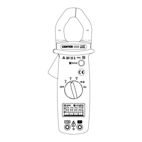
- Page 6 III. Instrument Familiarization: Current Sensing Clamp Safety protection ring Clamp opening handle Function select dial LCD display COM input terminal Positive input terminal Data hold button Battery cabinet...
- Page 7 Symbol Definition: Low battery indication AUTO Auto range indication Manual range indication Hold Data indication Continuity function indication Voltage measurement indication Current measurement indication Alternative source indication Direct source indication Polarity indication Analog bar graph indication MK Hz Frequency Measurement indication...
- Page 8 IV. Measuring Instruction: 4.1 ACA measurement: Switch the main function selector to A range. Open the clamp by pressing the jaw-opening handle and insert the cable to be measured into the jaw. Close the clamp and get the reading from the LCD panel. Note: Before this measurement, disconnect the test lead with the meter for safety.
- Page 9 4.2 ACV measurement: Switch the main function selector to V range. Connect red test lead to “+” terminal and black one to the “ COM “ terminal. Measure the voltage by touch the test lead tips to the test circuit where the value of voltage is needed. Read the result from the LCD panel.
- Page 10 4.3 DCV measurement: Switch the main function selector to V range. Connect red test lead to “+” terminal and black one to the “ COM “ terminal. Measure the voltage by touch the test lead tips to the test circuit where the value of voltage is needed. Read the result from the LCD panel.
- Page 11 4.4 Resistance measurement: Switch the main function to range. Connect red test lead to “+” terminal and black one to the “ COM ” terminal. Connect tip of the test leads to the points where the value of the resistance is needed. Read the result from the LCD panel.
- Page 12 4.5 Continuity Test: Switch the main function to range. Connect red test lead to “+” terminal and black one to the “ COM ” terminal. Connect tip of the test leads to the points where the conduction condition needed. If the resistance is under 40Ω, the beeper will sound continuously.
- Page 13 4.6 Frequency measurement from the terminals: Switch the main function to “ Hz ” range. Connect red test lead to “+” terminal and black one to the “ COM ” terminal. Connect tip of the test leads to the points where the value of the resistance is needed.
- Page 14 4.7 Frequency measurement with the clamp: Switch the main function selector to“ Hz ” range. Open the clamp by pressing the clamp-opening handle and insert the cable to be measured into the clamp. Close the clamp and get the reading form the LCD panel. Note: When doing frequency measurement, user should either use the terminal signal or clamp signal but not both.
- Page 15 V. Battery Changing: 1.When the battery voltage drop below proper operation range the symbol will appear on the LCD display and the battery need to changed. 2.Before changing the battery, switch the main dial to “OFF ” and disconnect test leads. Open the cover of the battery cabinet by a screwdriver.
- Page 16 * When take current measurement, keep the cable at the center of the clamp will get more accurate test result. * Repairs or servicing not covered in this manual should only by qualified personal.
- Page 17 CENTER TECHNOLOGY CORP. 4 / F NO. 415, Jung-Jeng Rd., 238 Shu-Lin, Taipei, Taiwan TEL : 886-2-26763926 E-Mail : center@centertek.com FAX : 886-2-26763925 http : / / www.centertek.com 200-02...
Need help?
Do you have a question about the 200 and is the answer not in the manual?
Questions and answers