
Subscribe to Our Youtube Channel
Related Manuals for Center 235


Summary of Contents for Center 235
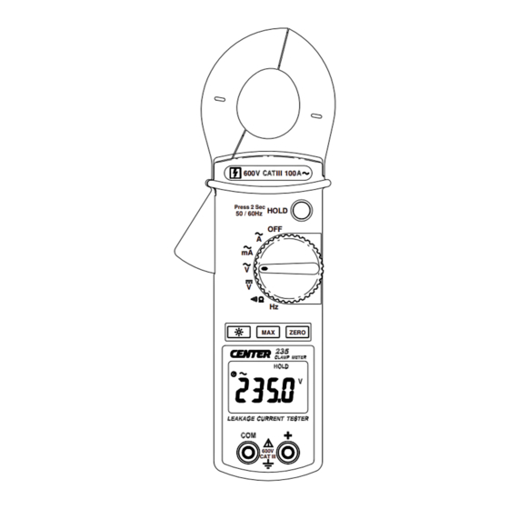
- Page 1 2 3 5 AC Cla m p M e t e r III 100 Press 2 Sec HOLD 50 / 60Hz ZERO 600V CAT III LEAK AGE CU RREN T T EST ER...
- Page 2 CONTENTS TITLE PAGE Safety Information ……………………….………….….1 Environmental Conditions……………………………………..….. 1 Explanation of Symbols…………….……………………….…….. 1 Specification…………………………...……………..…2 General Specification……………………………………………..2 Electrical Specification………………………………………….…. 3 III. Instrument Familiarization…………...………………..4 Symbol Definition…………………………………………………... 4 Instrument Familiarization…………………………………….……4 Button Instruction…………………………………………….…….. 4 IV. Measuring Instruction……………..……………….…..6 4.1 ACA...
- Page 3 Safety Information Do not operate the unit if the casing or the test Leads are or look damaged. Check the main function dial to ensure it is set at the correct position before each measurement. Do not perform resistance and continuity test on a live “powered “system.
- Page 4 II. Specification Ge ne ra l Spe c ific at ion: Digital Display: 4 digits LCD display with maximum reading 9999 Over Load: When the signal input exceeds the maximum limit “ OL ” will be display. Sample Rate: 2 times/sec Low Power Indication: When the battery is below the proper operation range, symbol...
- Page 5 Ele c t ric a l Spe c ific at ion:...
- Page 6 III. Instrument Familiarization: Sym bol De finit ion: 50/60Hz I nst rum e nt Fa m ilia rizat ion: III 100 Press 2 Sec HOLD 50 / 60Hz WARNING IEC 1010 600V CAT I I I POLLUTION DEGREE 2 ZERO 600V CAT III...
- Page 7 Max Hold Button Press “Max” button to enter the Max mode, “Max” Annunciate will appear and the Max display. Press the Max button again, to exit the Max mode. Back Light Function: Press the “Back Light” button will turn back light on and Press it once again will turn off.
- Page 8 IV. Measuring Instruction: 4.1 ACA...
- Page 9 Fig.2 Measuring out of balance leakage current: Load Load Press 2 Sec Press 2 Sec HOLD HOLD 50 / 60Hz 50 / 60Hz ZERO ZERO 600V CAT III 600V CAT III 3-Phase 3-Wire system Single-Phase 2-Wire system...
- Page 10 4.2 ACV measurement: WARN I N G! Maximum Input Voltage is 600V AC/DC. Do not attempt to Take any voltage measurement that may exceed this maximum to avoid Electrical shock hazard and/or damage to this instrument. Switch the function selector to V range.
- Page 11 4.3 DCV measurement: Switch the function selector to V range. Connect red test lead to “+” terminal and black one to the “ COM “ terminal. Measure the voltage by touching the test lead tips to the test circuit where the value of voltage is needed. Read the result from the LCD panel.
- Page 12 4.4 Resistance measurement: Switch the function selector to range. Connect red test lead to “+” terminal and black one to the “ COM ” terminal. Connect tip of the test leads to the points where the value of the resistance is needed. Read the Ohm value from the LCD panel.
- Page 13 4.5 Continuity Test: Switch the function selector to range. Connect red test lead to “+” terminal and black one to the “ COM ” terminal. Connect tip of the test leads to the points where continuity is to be tested. If the resistance is under 35...
- Page 14 4.6 Frequency measurement from the terminals: Switch the main function to “ ” range. Connect red test lead to “+” terminal and black one to the “ COM ” terminal. Connect tip of the test leads to the points where the frequency of the voltage signal is needed.
- Page 15 4.7 Frequency measurement with the clamp: Switch the main function selector to“ ” range. Open the clamp by pressing the clamp-opening handle and insert the cable to be measured into the clamp. Close the clamp and get the reading form the LCD panel. N ot e : When doing frequency measurement, user should either use the terminal signal or clamp signal but not both.
- Page 16 V. Battery Changing: 1.When the battery voltage drops below proper operation range the symbol will appear on the LCD display and the battery will need to be changed. 2.Before changing the battery, switch the function selector to “OFF ” and disconnect test leads. Open the back cover using a screw driver.
- Page 17 * Remove the batteries, if the meter is not used for extended periods of time. Do not store the meter in a high temperature/humidity environment. * When measuring current, keep the cable at the center of the clamp to get more accurate readings. CLEAN I N G Periodically wipe the case with a dry cloth and without detergent.
- Page 18 CENTER TECHNOLOGY CORP. 4 / F NO. 415, Jung-Jeng Rd., 238 Shu-Lin, Taipei, Taiwan TEL : 886-2-26763926 E-Mail : center@centertek.com FAX : 886-2-26763925 http : / / www.centertek.com 235-00...
Need help?
Do you have a question about the 235 and is the answer not in the manual?
Questions and answers