
Related Manuals for NUVE NF 3000R


Summary of Contents for NUVE NF 3000R
- Page 1 NF 3000R HIGH CAPACITY REFRIGERATED CENTRIFUGE USER’S MANUAL 1984 NÜVE SANAYİ MALZEMELERİ İMALAT VE TİCARET A.Ş. Z14.K25.154 REV.NO:13 REV.DATE:05/2023...
-
Page 2: Manufacturer
+(90) 312 399 28 30 (pbx) FAX: +(90) 312 399 21 97 E-mail: satis@nuve.com.tr BEFORE OPERATING THE INSTRUMENT THIS MANUAL SHOULD BE READ CAREFULLY. THE VALIDITY OF THE GUARANTEE IS SUBJECT TO THE OBSERVATION OF THE INSTRUCTIONS AND PRECAUTIONS DESCRIBED IN THIS MANUAL. -
Page 3: Warranty Certificate
In the event of failure, Nüve shall be under no liability for any injury, or any loss or damage as the result of the failure other than the guarantee conditions. DEAR NUVE USER We would like to take this opportunity to thank you for preferring this Nüve product. Please read the operating instructions carefully and keep them handy for future reference. - Page 4 PLEASE REGISTER ONLINE TO VALIDATE YOUR WARRANTY You can register your device by scanning the QR code on your device or by logging into the mynuve.info page. After reaching the page, click on the "Sign up" link. After entering the requested information on the page that opens, you can register your device by clicking the button.
-
Page 5: Table Of Contents
1.1. USE AND FUNCTION ......................6 SECTION 2 – TECHNICAL SPECIFICATIONS ..................7 2.1. TECHNICAL SPECIFICATIONS TABLE ................. 7 2.2. ACCESSORIES FOR NF 3000R ..................... 8 2.3. GENERAL PRESENTATION ....................9 2.4. ROTOR SELECTION TABLE ....................10 2.5. PRECAUTIONS AND USAGE LIMITATIONS ............... 10 SECTION 3 –... - Page 6 LOADING ..........................32 6.2.1 BLOOD BAG LOADING ....................33 ROTOR INSTALLATION ....................... 34 DRIVE SYSTEM ........................35 SECTION 7 – CLEANING AND PERIODIC MAINTENANCE ............... 35 PERIODIC MAINTENANCE ....................35 STERILIZATION ........................36 CORROSION INFORMATION ....................36 7.3.1 CHEMICAL CORROSION ....................36 7.3.2 STRESS CORROSION .....................
-
Page 7: Section 1 - Introduction
Control system; Provides display and control of speed (in RPM or RCF), acceleration, braking stage and run time. The NF 3000R centrifuge device is equipped with a cooling system that allows working in the range of -10 ºC, 40 ºC. -
Page 8: Section 2 - Technical Specifications
SECTION 2 – TECHNICAL SPECIFICATIONS 2.1. TECHNICAL SPECIFICATIONS TABLE TECH. SPECS. NF 3000R Rotor Type 4x750ml 4600 4637 Maximum Capacity/RPM/RCF 30x1.5/2ml 15000 24904 50x1.5/2ml 15000 22136/24904 Control System N-Prime™ Programmable Microprocessor Control Display N-Wise™ - 7” Touch Screen (800x480) Programs... -
Page 9: Accessories For Nf 3000R
2.2. ACCESSORIES FOR NF 3000R B50 036 SWING-OUT ROTOR SEALING CAP – SET OF BUCKETS G51 044 35x5ml RIA – SET OF INSERTS G51 050 22x5ml – SET OF INSERTS G51 045 22x7ml – SET OF INSERTS G51 051 19x15ml – SET OF INSERTS G51 046 13x15ml Conical –... -
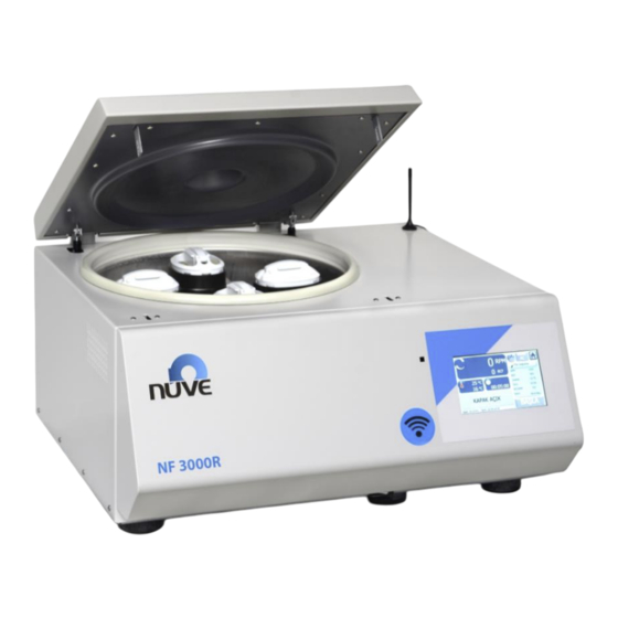
Page 10: General Presentation
GENERAL PRESENTATION Figure 1 – NF 3000R Rotor&Bucket LID Lock Manual LID Opening Hole Wi-Fi Antenna Control Unit Cooling Ventilation 10 ON/OFF Switch LID Damper 11 LID Gasket Chamber 12 Power Cable... -
Page 11: Rotor Selection Table
2.3. ROTOR SELECTION TABLE Swing-Out Rotor and Acce ssories MAX. RAD. MAX. ROTOR DESCRİPTİON CAPACITY TUBE (MM) DIM (MM) B50 036 Swing-Out 4x750 ml 4600 4637 Set of 4 Bucket 1x750 ml Set of 4 Inserts 35x5 ml-Ria Set of 4 Inserts 22x5 ml Set of 4 Inserts 22x7 ml... - Page 12 Ensure that the rotor is placed correctly prior to usage. • Do not open the lid while rotor is spinning. • Use only the the spare parts, rotors and accessories which are supplied by NUVE. • Load the rotor according to the explanations in the user’s manual. •...
-
Page 13: Section 3 - Symbols
SECTION 3 – SYMBOLS Symbol in the operating instructions: Attention, general hazard area. This symbol refers to safety relevant warnings and indicates possibly dangerous situations. The non-adherence to these warnings can lead to material damage and injury to personal. Symbol in the operating instructions: This symbol refers to important circumstances. -
Page 14: Section 4 - Installation
Labels on the product: SECTION 4 – INSTALLATION 4.1. LIFTING AND TRANSPORT Because of the heavy weight of the centrifuge, all lifting and transport must be carried out using proper handling equipment. The centrifuge should be lifted from underneath and never be turned over. -
Page 15: Positioning
4.3. POSITIONING • Check that no damage has occurred during transport. • Check that the positioning is suitable for users. • Lift the centrifuge (use proper handling equipment if necessary) underneath and carry it to its place. • The bench-top must be rigid enough to support the weight and vibrations. •... -
Page 16: Section 5 - Operating Unit
SECTION 5 – OPERATING UNIT 5.1. OPERATING • Open the lid and check that there is no sample in the instrument. • Turn the centrifuges on by using On/Off switch. • See that the display and control panel activates. • Learn the functions of the control panel (See Part 5.2). -
Page 17: Working Screen
5.2.2 WORKING SCREEN Figure 3 – Working Screen 01-Working Animation It shows the motor/rotor are spinning. 02-Speed It shows the RPM / RCF values read from the device. For the area of RPM / RCF values, the selection varies according to the unit value that it has chosen. 03-Time Button The forward / backward counting preference of the time parameter entered via the button is changed. -
Page 18: User's Setting
08-Programs Reachable to pre-set programs. 09-Program Detail Details of the selected program. 10-Function Button Start(green), Stop(red), Delay(yellow) and if it is gray, it is passive. 11-Status Display It shows tp notifications, errors and working phases. 12-Chamber Temperature It is the chamber temperature. It is not the temperature of sample. Please be careful for this while setting the temperature! 13-Condenser/Ambient Temperature 14-Temperature Button... -
Page 19: Memory
When the device is installed, the admin and operator passwords are as follows: Admin: "0000" Operator 1: "1111" Operator 2: "2222" It is recommended to change passwords after device setup. 03-Language 04-Wi-Fi Setting SSID(Wi-Fi name) and password. 05-Confirm Button Back to the main menu with saving any changes. 06-Back(ESC) Button Back to the main menu without saving any changes. -
Page 20: Info/Help
Rotor Cycle Info 03-Back(ESC) Button 04-Main Menu Button 5.2.5 INFO/HELP Figure 6 – Info/Help There is also some information in the user manual that adapts to the easy use. Also the menu shows HMI and MK software version. 5.2.6 PROGRAMS Figure 7 –... - Page 21 Figure 8 01-Forward/Backward It changes the page. 02-Program It reaches the program setting page and program details. 03-Back(ESC) Button 04-Main Menu Button 05-Rotor List 06-RPM Value RPM value is entered with numpad keyboard. 07-RCF Value RCF value is entered with numpad keyboard. 08- Authorization Authorization for the program.
-
Page 22: Making A Program
10-Deceleration Value 11-Acceleration Value 12-Chamber Temperature Value It is the chamber temperature. It is not the temperature of sample. Please be careful for this while setting the temperature! 13-Centrifuge Time 14- Program Name It is entered with keyboard. 15- Confirm Button Back to the main menu with saving any changes. - Page 23 Choose from 99 customizable programs. The program screen you selected will be as shown in the figure. Set the options you selected step by step. Select the Rotor tab. Select the rotor you have determined from the list in the pop-up windows that comes up.
- Page 24 Select the Temperature tab. Enter the value you set on the numerical keyboard (numpad) that comes up. It is the chamber temperature. It is not the temperature of sample. Please be careful for this while setting the temperature! Select the ACC level tab. Enter the value you set on the numerical keyboard (numpad) that comes up.
-
Page 25: Selecting The Memorized Program
After making all the program settings, save by pressing the CONFIRM button. If you press the BACK or MAIN MENU button, you will exit without saving.. Figure 9 The correct rotor type should be selected in order to see the correct RCF values during the run. - Page 26 Place your samples and close the lid of the device. Select the program you want to work from the list of programs that comes up by pressing the PROGRAMS button. Check device from STATUS DISPLAY. With the device in the READY position, start the device by pressing the FUNCTION BUTTON (START).
-
Page 27: Pulse Mode
Pre-Cooling; If the program temperature you are working on NF 3000R is lower than the ambient temperature, run the Pre-Cooling process without sample before the program you will run to achieve maximum performance. When the value on the screen reaches the set temperature, stop the program. -
Page 28: Pre Cooling Program
Check device from STATUS DISPLAY. With the device in the READY position, start the device by pressing the PULSE button. You can reach the desired speed by HOLDING down the PULSE button within the RPM speed limits you set. • In the PULSE mode, the rotor operates according to the set acceleration and braking values you set. -
Page 29: End Of Operation
END OF OPERATION At the end of the cooling operation with the NF 3000R centrifuges, dry with a non-wool soft cloth or paper towel at the centrifuge cell. (When the end of cooling operation with NF 3000R, has a puddle at the centrifuge cell. -
Page 30: Cooling Setting
To avoid facing imbalance problem, please make sure to insert the tubes correctly. COOLING SETTING The device has a cooling system that allows it to operate at temperatures between -10°C and + 40°C. Since there is no heating system in the device, the temperature setting is used only as a cooling process to the desired degree. -
Page 31: User's Setting
5.10 USER’S SETTING Select the USER’S SETTING menu from the main menu. Login with your password. Click on the Date / Time icon to adjust the Date and Time settings. You can make your selection with the green forward / backward arrows to select "Month". To enter “year”, you can select the place it wrote and make your selection with the up / down arrows. - Page 32 Select the place it wrote for the e-mail address, enter the name you specified with the keyboard and save it with ENTER. Enter the e-mail addresses according to as shown in the figure. If you want to use the E-Mail feature, set the STATUS tab to ON.
-
Page 33: Section 6 - Operating Principles
SECTION 6 – OPERATING PRINCIPLES PREPARATION OF THE ROTOR TO RUN Before installation, check the rotor for corrosion and cleanliness. Chemical corrosion or mechanical corrosion may do severe damage to the rotor and the centrifuge. Particles which are stuck inside the inserts cause the breakage of tubes and lead to major imbalance please check to make sure that no particles are left on the rotor. -
Page 34: Blood Bag Loading
Examples of the proper and improper loading are shown below. Figure 12 6.2.1 BLOOD BAG LOADING • Blood is taken into a closed and sterile triple bag system. • The declared size is filled up to 450 ml in the blood bag. •... -
Page 35: Rotor Installation
Figure 13 – Weighed Baskets • After this procedure is applied, the samples are placed on the carrier mutually symmetrically. (See Figure 14). Figure 14 If a working (cooled) operation is made below room temperature, it is recommended to run "Pre-Cooling" program with baskets only before centrifugation. -
Page 36: Drive System
Figure 15 – Gap on the Rotor DRIVE SYSTEM • The rotor is driven by a three phase asynchronous motor. The microprocessor control system assures the correct drive speed. • The force applied to the rotor is directly related to the shape of the rotor, the swing-out rotor receives more load than the angle rotor does. -
Page 37: Sterilization
Glutaraldehyde is a toxic substance and increases the rate of fatty acid in the body. CORROSION INFORMATION • Nuve rotors which are made of aluminum are designed to spin at proper RCFs for many years. When used properly, their resistance to corrosion and their life span increases and the imbalance problems decrease. -
Page 38: Electricity
the corrosive chemical, the stress corrosion starts. This type of corrosion is even more dangerous than the chemical corrosion as the effects of this corrosion are microscopic and very difficult to observe in the course of time. • The corrosive material is pushed against the aluminum alloy by the centrifugation “g” force during the centrifugation. - Page 39 It is imbalance (imbalanced load) error. Check whether the weights in the baskets or sample slots are equal. Chamber Temperature Sensor Connection Error(SBR PT Cell) It occurs when the ends of the temperature sensor are broken. Condenser Temperature Sensor Connection Error SBR PT Condenser It occurs when the ends of the temperature sensor are broken.
-
Page 40: Section 10 - Electrical Circuit Diagram
SECTION 10 – ELECTRICAL CIRCUIT DIAGRAM...
Need help?
Do you have a question about the NF 3000R and is the answer not in the manual?
Questions and answers