Sign In
Upload
Download
Table of Contents
Contents
Add to my manuals
Delete from my manuals
Share
URL of this page:
HTML Link:
Bookmark this page
Add
Manual will be automatically added to "My Manuals"
Print this page
×
Bookmark added
×
Added to my manuals
Manuals
Brands
NUVE Manuals
Laboratory Equipment
NC 23S
User manual
NUVE NC 23S User Manual
Bench top steam sterilizers
Hide thumbs
1
2
3
Table Of Contents
4
5
6
7
8
9
10
11
12
13
14
15
16
17
18
19
20
21
22
23
24
25
26
27
28
29
30
31
32
33
34
35
36
page
of
36
Go
/
36
Contents
Table of Contents
Troubleshooting
Bookmarks
Table of Contents
Table of Contents
1 Introduction
Use and Function
2 Technical Specifications
Technical Specifications Table
Accessories
Optional Accessories
3 Precautions and Limitations on Use
4 Symbols and Labels
5 Installation
Environmental Conditions
Handling and Transportation
Unpacking
Mains Supply
Positioning
General Presentation
Control Panel
Prior to Operation
Connection to Mains
Connection to Water Supply
Attaching Microbiological Filter
Sterilization Programs
Packaging
Loading
Textiles
Instruments
Sterilization Bags
6 Operating Principles
Operation Phases
Programming
Special Programs
Test Programs
Completion of the Operation
Unloading and Preserving
7 Menus
Help
Memory
External Memory (Usb Stick)
Settings
Preheating
Standby
Printer
Buzzer
Setup
Time/Date
Language
Password
Sms
E-Mail
C/Bar
Service
8 Periodic Maintenance and Cleaning
Periodic Maintenance
Periodic Contol
Cleaning
9 Disposal Management Concept
10 Troubleshooting
Error Codes
Fuse Replacement
11 Options
Alertext™ GSM MODULE
12 Electrical Circuit Diagram
Nc 23S/32S Electrical Circuit Diagram
Advertisement
Quick Links
Download this manual
NÜVE SANAYİ MALZEMELERİ İMALAT VE TİCARET A.Ş.
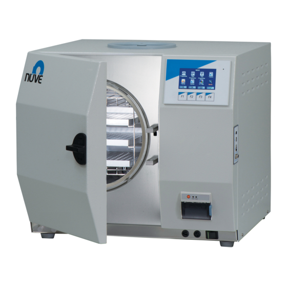
NC 23S / NC 32S
BENCH TOP STEAM STERILIZERS
USER'S MANUAL
1984
Z14 K25 246
Rev.No: 13 Rev.Date: 11/ 2017
Table of
Contents
Previous
Page
Next
Page
1
2
3
4
5
Advertisement
Table of Contents
Need help?
Do you have a question about the NC 23S and is the answer not in the manual?
Ask a question
Questions and answers
Related Manuals for NUVE NC 23S
Laboratory Equipment NUVE NB 5 User Manual
Water baths (21 pages)
Laboratory Equipment NUVE NB 9 User Manual
Water baths (21 pages)
Laboratory Equipment NUVE NB 20 User Manual
Water baths (21 pages)
Laboratory Equipment NUVE NF48 User Manual
Bench top centrifuge (18 pages)
Laboratory Equipment NUVE NF 048 User Manual
(17 pages)
Laboratory Equipment NUVE NF 1200 User Manual
Multi-purpose bench top centrifuges (23 pages)
Laboratory Equipment NUVE NC 32S User Manual
Bench top steam sterilizers (36 pages)
Laboratory Equipment NUVE NC 23B User Manual
Bench top steam sterilizers (36 pages)
Laboratory Equipment NUVE NF200 User Manual
(18 pages)
Laboratory Equipment NUVE NF 200 User Manual
Bench-top centrifuge (17 pages)
Laboratory Equipment NUVE NC 300 User Manual
(35 pages)
Laboratory Equipment NUVE NC 570 User Manual
(35 pages)
Laboratory Equipment NUVE NF 3000R User Manual
High capacity refrigerated centrifuge (40 pages)
Laboratory Equipment NUVE EN 300 User Manual
Incubators (20 pages)
Laboratory Equipment NUVE ST 30 User Manual
Shaking water bath (17 pages)
Laboratory Equipment NUVE OT 020 Service Manual
Bench top steam sterilizers (31 pages)
This manual is also suitable for:
Nc 32s
Table of Contents
Print
Rename the bookmark
Delete bookmark?
Delete from my manuals?
Login
Sign In
OR
Sign in with Facebook
Sign in with Google
Upload manual
Upload from disk
Upload from URL


Need help?
Do you have a question about the NC 23S and is the answer not in the manual?
Questions and answers