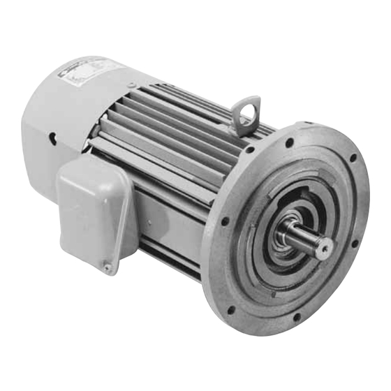
Download Print this page
Sumitomo FB-01A1 Operating And Maintenance Manual

Sumitomo FB-01A1 Operating And Maintenance Manual

3-phase motor brake

Advertisement

Quick Links

3-PHASE MOTOR BRAKE
(FB-01A1 FB-30, CMB-20)
3-phase motor brake should be handled, installed and maintained by trained
technicians.
Carefully read the maintenance manual before use.
A copy of this maintenance manual should be sent to the actual user of 3-phase
motor brake.
This maintenance manual should be maintained by the user.
Operating and Maintenance Manual MM0202E
-8

Advertisement

loading
Need help?

Need help?

Do you have a question about the FB-01A1 and is the answer not in the manual?

Questions and answers

Summary of Contents for Sumitomo FB-01A1

  • Page 1 3-PHASE MOTOR BRAKE (FB-01A1 FB-30, CMB-20) 3-phase motor brake should be handled, installed and maintained by trained technicians. Carefully read the maintenance manual before use. A copy of this maintenance manual should be sent to the actual user of 3-phase motor brake.
  • Page 2 Safety and Other Precautions • Carefully read this maintenace manual and all accompanying documents before use (installation, operation, maintenance, inspection, etc.) Thoroughly understand the machine, information about safety, and all precautions for correct operation. Maintain this manual for future reference. •...
  • Page 3 CAUTION (Inspection upon delivery) Unpack the unit after verifying that it is positioned right side up; otherwise, injury may result. Verify that the unit received is in fact the one that is ordered. When a different unit is installed, injury or damage to the equipment may result.
  • Page 4: Table Of Contents

    • For handling of motors and gear motors , refer to the respective maintenance manuals. CONTENTS 1. Type of brake  ………………………………………………………………………………………………4 2. Wiring  ………………………………………………………………………………………………………4 3. Maintenance and Inspection of FB brake ………………………………………………………………10 4. Maintenance and Inspection of CMB brake ……………………………………………………………22 5. Troubleshooting  …………………………………………………………………………………………24...
  • Page 5: Type Of Brake

    Type of brake Frast braking 3-phase motor action motor action (3-phase inverter (4-pole) action J (kg·m (4-pole) (3-phase motor) motor) FB-01A1, FB - 01A 0.1kW 0.00035 0.15~0.2 0.015~0.02 FB-02A1, FB - 02A 0.2kW 0.1kW 0.00055 0.08~0.12 FB-05A1, FB - 05A 0.4kW 0.2kW 0.00068...
  • Page 6 Fig. 1 2-2) Connection for motor with FB brake Fig. 2 shows the standard connection for 3-phase motors with FB-01A1~FB-15B brake and terminal codes. Fig. 2 Connection for motor with FB brake and terminal code FB - 01A1~FB - 05A1...
  • Page 7 • The brake delay time of the normal braking action is diffierent from that of the fast braking action. Table 1 on page 4 shows the delay time. Use a circuit that meets your requirements. • DC braking capacity (for DC coil loading) exceeding 5 times the braking current shown on the name plate is recommended for the fast braking action.
  • Page 8 • Pay attention to the following items when driving a inverter • For inverter-driving the motor with a brake, use the primary-side power supply for braking as shown in Fig.2, and synchronize the braking operation with the ON/OFF operation of the unit. •...
  • Page 9 2-3) Connection for motor with CMB motor Figure 5 shows the standard connection for 3-phase motors with CMB-20 brake and terminal codes. Fig. 5 Connection for motor with CMB brake and terminal code CMB-20 Type of brake 200V-class 400V-class R S T R S T Star connection Star connection...
  • Page 10 : Electromagnetic contactor OLR : Overload prevention device To be furnished customers. : Discharging resistor (for protection of contact) • Use a 5~10 Watt, 200~300Ω resistor as r (discharging resistor). • The brake delay time of the normal braking action is different from that of the fast braking action. Table 1 on page 3 shows the delay time.
  • Page 11: Maintenance And Inspection Of Fb Brake

    Assembling bolt Boss Shaft retaining C-ring Cover Fan set bolt Fan(Not provided for FB-01A1 and FB-01A) Leaf spring Fixed plate Armature plate Spring Electromagnetic coil G Ball bearing Motor shaft Fig. 6 FB-01A1, 02A1, 05A1, 01A, 02A and 05A (Indoor type)
  • Page 12 Part name 11 10 9 Stationary Rlease fitting Manual release prevention spacer Brake release bolt Spacer Gap adjusting shim Assembling bolt Brake lining Leaf spring Boss Shaft retaining C-ring Cover Fan setting bolt Fixed plate G Armature plate Spring Electromagnetic coil Ball bearing Motor shaft Fig.
  • Page 13 Part name Roller Brake release bolt Auxiliary spring Plug Stationary core Electromagnetic coil Stud bolt brake lining Adjusting washer Spring washer Gap adjusting nut Boss Shaft retainig Cover Fan setting bolt Leaf spring Fixed plate Armature core Spring Stud bolt 15 16 17 21 22 23 24 25 26 18 19...
  • Page 14 Stationary core Ball bearing Motor shaft Fan setting bolt Note 1: 67, and @0 are not provided for FB- Fig. 12 FB-01A1, 02A1, 05A1, 01A, 02A, and 05A (Outdoor type) 01A1 and 01A. Part name Armature plate Brake lining Spacer...
  • Page 15 Part name Stationary core Release fitting 11 10 Stud bolt Adjusting washer Manual release prevention spacer Brake release bolt Spring washer Gap adjusting nut Brake lining Boss Shaft retaining C-ring Cover Spring pin Leaf spring Fixed Plate Armature core Spring G...
  • Page 16 Part name Roller Brake release bolt 14 13 12 11 10 9 Auxiliary spring Plug Stationary core Electromagnetic coil Stud bolt Brake lining Adjusting washer Spring washer Gap adjusting nut Boss Shaft retaining Waterproof cover V-ring Outdoor cover Cover Fan setting bolt Leaf spring Waterproof cover mounting bolt Packing...
  • Page 17 3-2) Manual release operation of FB brake (FB-01A1~05A1 Optional : FB01A~05A) To manually release the brake without turning on the power, operate the brake release device in the following manner: (1) Remove the brake release bolts arranged diagonal to each other, and remove the spacer. Then screw in the bolts with a hexagon wrench, and the brake will be released.
  • Page 18 3-4) Adjustment of gap When the gap nears the limit shown in Table 3 during inspection, adjust the gap in the following manner: A. Indoor type <FB-01A1, 02A1, 05A1, 01A, 02A, and 05A> (See Fig.6 on page 9.) (1) Remove cover 7.
  • Page 19 <FB-1B, 2B1 and 3B> 11 10 9 (See Fig.7 on page 10.) (1) Remove brake release bolt 4, and manual release prevention spacer 3. (2) Remove cover !2 . (3) Remove fan setting bolt !3 , and remove fan !4 . (4) Loosen assembling bolt 7, and remove spacer 5, gap adjusting shim 6, assembling bolt 7, and fixed plate !5 all together as a set.
  • Page 20 B. Outdoor type <FB-01A1, 02A1, 05A1, 01A, and 05A> (See Fig.12 on page 13.) (1) Remove cover !1 . (2) Loosen fan setting bolt @0 and remove fan 6. G (3) Pull out V-ring 7. (4) Remove waterproof cover mounting bolt !3 , and remove waterprof covrer !2 .
  • Page 21 <FB-5B, 8B, 10B, and 15B> (See Fig.13 and 14 on page 13.) (1) Remove release bolt 6 and manual release prevention spacer 5. (2) Remove cover !2 . 11 10 (3) Remove spring pin !3 from FB-8B and FB-5B, and remove fan !4 .
  • Page 22 When the thickness of the brake lining has reached the limit shown in Table 4 (when the brake gap has reached the limit shown in Table 3 on page 12 after gap adjustment in the case of FB-01A1, 02A1, 05A1, 01A, 02A, and 05A), ask us to replace the brake lining at our specialized plant.
  • Page 23: Maintenance And Inspection Of Cmb Brake

    4. Maintenance and Inspection of CMB Brake DANGER Do not handle the unit when cables are live. Be sure to turn off the power; otherwise, electric shock may result. When the unit is to be used for an elevator, do not release the brake of the unit during lifting the unit; otherwise, the unit may fall.
  • Page 24 4-2) Manual releasing operation of CMB brake To manually release the brake without turning on the power, opetate the brake release device in the following manner (Fig.16 on page 17): (1) Remove plug 5, and turn release bolt 3 in the loosening direction (clockwise with a hexagon wrench (for M8 bolt with a hole).
  • Page 25: Troubleshooting

    5. Troubleshooting When some trouble occurs the motor with the brake, take appropriate measures without delay according to Table 6. Table 6 Troubleshooting Details of trouble Cause Correction Power failure Contact the electric power company. Defective electric circuit Check the circuit. Fuse melting Replace the fuse with a new one.
  • Page 26: Warranty

    6. Warranty The scope of our warranty for our products is limited to the range of our manufacture. Warranty (period and contents) Warranty The warranty for new Cyclo, units shall be 24 months from date of shipment. Period In the event that any problem or damage to the Product arises during the "Warranty Period" from defects in the Product whenever the Product is properly installed and combined with the Buyer's equipment or machines, maintained as specified in the maintenance manual, and properly operated under the conditions described in the catalog or as otherwise agree upon in writing between the Seller and the Buyer or its customers;...
  • Page 27 National Telephone Number: 1 3000 DRIVE Fax: (55) 11-5585-9990 Tel: (49) 8136-66-0 Fax: (49) 8136-5771 Philippines Chile Sumitomo (SHI) Cyclo Drive Asia Pacific Pte. Ltd. SM-Cyclo De Chile, Ltda. Austria Representative Office in Philippines San Pablo Ave, 3507 Quinta Nomal SCG Branch Austria Office...