Table of Contents
Advertisement
Quick Links
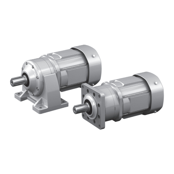
ALTAX® NEO
Gearmotor
Reducer
Application Product : ALTAX®NEO with Current Limiter
<<CAUTION>>
■ The product should be handled by an experienced and skilled personnel.
Read the maintenance manual thoroughly before using the product.
■ The maintenance manual should be delivered to a customer who uses the product.
■ Make sure the maintenance manual should be stored securely.
Maintenance manual No.CM2015E-8
Advertisement
Chapters
Table of Contents

Related Manuals for Sumitomo ALTAX NEO


Summary of Contents for Sumitomo ALTAX NEO
- Page 1 ALTAX® NEO Gearmotor Reducer Application Product : ALTAX®NEO with Current Limiter <<CAUTION>> ■ The product should be handled by an experienced and skilled personnel. Read the maintenance manual thoroughly before using the product. ■ The maintenance manual should be delivered to a customer who uses the product. ■ Make sure the maintenance manual should be stored securely.
-
Page 3: Introduction: Safety Precautions
Introduction: Safety Precautions - Carefully read this maintenance manual and all accompanying documents before use (installation, operation, maintenance, inspection, etc.). Thoroughly understand the machine, information about safety, and all precautions for correct operation. After reading, retain this manual for future reference. - Pay close attention to the "DANGER"... -
Page 4: Table Of Contents
Introduction: How to Refer to the Maintenance Manual, Table of Contents This maintenance manual is common for “gearmotors”, “reducers”. The symbols shown below appear in the upper right or left corner of each page to indicate the classification. Please read the applicable pages. Common pages, symbols identify distinctions between specific specifications. -
Page 5: Inspection Upon Delivery
Common 1. Inspection upon Delivery CAUTION - Unpack the unit after verifying that it is positioned right side up; otherwise, injury may result. - Verify that the unit received is in fact the one you ordered. Installing the wrong unit may result in personal injury or equipment damage. - Page 6 1. Inspection upon Delivery 1-2 Lubrication Method ALTAX NEO and ALTAX Low Reduction Ratio Series adopt grease lubrication and grease is applied when shipped from the factory, therefore lubrication is not needed and use out of the box. 1-3 Gearmotor, Reducer Type Symbol meanings are shown below.
- Page 7 1. Inspection upon Delivery 1-4 Gearmotor Specification Symbol Symbol meanings are shown below. Please confirm that the type matches the order. A specification symbol is described on the nameplate when a customer specified at its order. xxth Digit ▼ ▼ Terminal box mounting position 5th Digit Operating environment...
- Page 8 1. Inspection upon Delivery 1-5 Motor Type Symbol meanings are shown below. Please confirm that the specification matches the order. ▼ Type Single phase Blank 3-phase ▼ Support for Standards and Regulations ▼ ▼ Premium e ciency motor Drive Power Source Type of Sheath Totally enclosed Inverter drive...
-
Page 9: Storage
Common 2. Storage If this product is not for immediate use, note the following points when storing it. 2-1 Storage Location Store the product indoors in a clean, dry location. Do not store outdoors. Store in a location that is free of moisture, dust, extreme temperature changes, corrosive gases, etc. -
Page 10: Transport
Common 3. Transportation DANGER - Do not stand directly under a unit suspended by a crane or other lifting mechanism; otherwise, injury, or death may result. CAUTION - Exercise ample care so as not to drop the unit. When a hanging bolt or hole is provided, be sure to use it. After mounting a unit to a machine, do not hoist the entire machine using the hanging bolt or hole;... -
Page 11: Installation
Common 4. Installation DANGER - Do not use a standard unit in an explosive atmosphere (which is likely to be filled with explosive gas or steam). Under such conditions, an explosion-proof motor should be used; otherwise, electric shock, personal injury, explosion fire, or damage to the equipment may result. - Page 12 Common 4. Installation 4-2 Mounting Angle There is no limit on a mounting angle. There is no limitation on a mounting angle unless it is originally specified the certain angle in manufac- turing. Do not remove the motor’s eye-bolt. In the rare case that it is removed, insert a bolt or other appropriate material into the screw hole to prevent water or other substances from entering the motor through the screw hole.
-
Page 13: Coupling With Other Machines
When wiring is performed as shown on P16 – 30, the motor shaft rotates to the right as seen from the anti-load side. In the following diagrams, arrows show the direction of slow speed shaft rotation in this case. ALTAX ALTAX NEO Low Reduction Ratio Series... - Page 14 Common 5. Coupling with Other Machines 5-2 Mounting Connected Equipment Connected - When mounting connected equipment, do not apply impact or Shaft equipment excessive axial load to the shaft. The bearing could be damaged, or the collar could come off. - Shrinkage or shaft-end screw fit is recommended (see Figure 5-1).
-
Page 15: Wiring
6. Wiring When using other manufacturer’s motor, follow the operation manual for that motor. This manual shows wiring for motors with Japanese standard specifications. Please consult with us for motors with overseas specifications. DANGER - Do not handle the unit when cables are live. Be sure to turn off the power; otherwise, electric shock may result. - Page 16 6. Wiring 6-1 Removing and Attaching the Resin Terminal Box Cover 3-phase motor: 0.1–0.4kW, high-efficiency, 3-phase motor: 0.2kW, 3-phase motor for inverter: 0.1–0.2kW (1) Removal As shown in figure 6-1, to remove the cover, grab the sides of the terminal box, and pull it toward you. (2) Attachment Push the terminal box cover from above the terminal box case until a click is heard.
- Page 17 6. Wiring 6-5 Motor Wiring Shows the pages for motor wiring diagrams. Table 6-2 Without Brake Page Capacity range Number of Direct input from Motor type Inverter (kW) lead wires commercial drive power source Standard 40W–0.55 3-phase motor Increased safety, 0.1 - 3.7 explosion proof Standard...
- Page 18 6. Wiring Shows motor wiring and standard specification for terminals and lead wires that are indicated by symbols. ■ Without brake. 3-phase power source 3-phase motor Premium-Efficiency, 3-Phase Motor High-efficiency 3-phase motor 3 Lead Wires 40–90W, 0.1kW (frame size 5067 only) 0.1–3.7kW White Black...
- Page 19 6. Wiring ■ Without brake. Inverter drive 3-phase motor Premium-Efficiency, 3-Phase Motor 3-phase motor for inverter Premium-efficiency, 3-phase motor for inverter High-efficiency 3-phase motor 3 Lead Wires 40–90W, 0.1kW (frame size 5067 only) 0.1–3.7kW Inverter Inverter White Black Motor Motor MCB : Breaker for wiring - Customer to prepare.
- Page 20 6. Wiring ■ Without brake. Single phase power source Single phase motor Single phase reversible motor Capacitor run 40–90W 100V class 200V class White Black Blue White Black Brown Motor Motor Switch the above SW for both-direction rotation. (Use a reversible motor when an immediate both-direction rotation is required.) : Electromagnetic contactor : Overload protection device or electronic thermal relay Customer to prepare.
- Page 21 6. Wiring ■ Without brake. Single phase power source Single phase motor Capacitor starting capacitor run 0.1–0.4kW 100V class 200V class Motor Motor Reverse Normal Reverse Normal rotation rotation rotation rotation U1 V2 U1 V1 U2 V2 Motor Motor MC: Electromagnetic contactor OLR: Overload protection device or electronic thermal relay Customer to prepare.
- Page 22 6. Wiring ■ With brake. 3-phase power source. Operates rotating in one direction. 3-phase motor MB-003 to 010 5 Lead Wires Yellow Yellow White Black Motor Brake YellowYellow White Black Motor Brake MC: Electromagnetic contactor Customer to prepare. OLR: Overload protection device or electronic thermal relay - This diagram shows cases for motors with standard Japanese domestic specifications.
- Page 23 6. Wiring ■ With brake. 3-phase power source. Operates rotating in one direction. 3-phase motor Premium-Efficiency, 3-Phase Motor High-efficiency 3-phase motor FB-01A1 - 05A1 FB-1D, FB-1E to 5E 5 Lead Wires Rectifier Brake Rectifier Brake Motor Motor Rectifier Brake Rectifier Brake Motor Motor...
- Page 24 6. Wiring ■ With brake. 3-phase power source. Both-direction operation 3-phase motor MB-003 to 010 5 Lead Wires R S T Normal Reverse rotation rotation Yellow Yellow White Black Motor Brake R S T Reverse Normal rotation rotation Yellow Yellow White Black Motor...
- Page 25 6. Wiring ■ With brake. 3-phase power source. Both-direction operation 3-phase motor Premium-Efficiency, 3-Phase Motor High-efficiency 3-phase motor FB-01A1 - 05A1 FB-1D, FB-1E to 5E 5 Lead Wires Normal Reverse Normal Reverse rotation rotation rotation rotation Rectifier Brake Rectifier Brake Motor Motor Normal ...
- Page 26 6. Wiring ■ With Brake. Inverter Drive 3-phase motor MB-003 to 010 5 Lead Wires Inverter Yellow Yellow White Black Motor Brake : Electromagnetic contactor Customer to prepare. MCB : Breaker for wiring - This diagram shows cases for motors with standard Japanese domestic specifications. Please consult with us for motors with overseas specifications.
- Page 27 6. Wiring ■ With Brake. Inverter Drive 3-phase motor Premium-Efficiency, 3-Phase Motor 3-phase motor for inverter Premium-efficiency, 3-phase motor for inverter High-efficiency 3-phase motor FB-01A1 - 05A1 FB-1D, FB-1E to 5E 5 Lead Wires Inverter Inverter Rectifier Brake Rectifier Brake Motor Motor Inverter...
- Page 28 6. Wiring ■ With brake. Single phase power source Single phase motor Single phase reversible motor MB-003 to 010 Capacitor run 100V class 200V class Yellow Yellow Yellow Yellow White Black Blue White Black Brown Motor Brake Motor Brake Yellow Yellow Yellow Yellow White Black...
- Page 29 6. Wiring ■ With brake. Single phase power source. Operates rotating in one direction. Single phase motor FB-01A1, 02A1 Capacitor starting capacitor run 100V class 200V class Recti er Brake Recti er Brake Motor Motor Recti er Brake Recti er Brake Motor Motor...
- Page 30 6. Wiring ■ With brake. Single phase power source. Operates rotating in one direction. Single phase motor FB-1D Capacitor starting capacitor run 100V class 200V class Recti er Brake Recti er Brake Motor Motor Recti er Brake Recti er Brake Motor Motor : Electromagnetic contactor...
- Page 31 6. Wiring ■ With brake. Single phase power source. Both-direction operation Single phase motor FB-01A1, 02A1 Capacitor starting capacitor run 100V class 200V class Reverse Normal Reverse Normal rotation rotation rotation rotation Recti er Brake Recti er Brake Motor Motor Reverse Normal ...
- Page 32 6. Wiring ■ With brake. Single phase power source. Both-direction operation Single phase motor FB-1D Capacitor starting capacitor run 100V class 200V class Reverse Normal Reverse Normal rotation rotation rotation rotation Recti er Brake Recti er Brake Motor Motor Reverse Normal ...
- Page 33 6. Wiring 6-6 Points to Note when Using a Quick Braking Circuit When using brakes with quick braking circuits, take note of the following items. - Connect a varistor (protection element) to protect the quick braking circuit contact points from surge voltage generated by the brake action.
- Page 34 6. Wiring - This recommended contactor type is for Fuji Electric FA Components & Systems Co., Ltd. and Mitsubishi Electric Corporation contactors. Products from other manufacturers are also allowable if they have equivalent capabilities. - Recommended contactor contact point capacity indicates rated DC-13 class current in the main contact point in the case where durability regarding electronic opening and closing (service life) is approximately 2 million times.
-
Page 35: Operation
Common 7. Operation DANGER - Do not approach or touch rotating parts (slow speed shaft, etc.) during operation; otherwise loose clothing may became caught in these rotating parts and cause serious injury or death. - When the power supply is interrupted, be sure to turn off the power switch. Unexpected resumption of power may cause electric shock, personal injury, or damage to the equipment. - Page 36 Common 7. Operation 7-1 Items to Check Before Operation After installation and wiring are completed, check the following items before operating. - Is the wiring correct? - Is the unit properly coupled with the driven machine? - Are mounting bolts tightened firmly? - Is the direction of rotation as required? After confirming these items, operate without a load and gradually apply a load.
- Page 37 7. Operation 7-3 Brake Torque and Activation Delay Time The table below shows standard specification brake types, their brake torque, and their relationship to brake activation delay time. Table 7-2 Brake Torque and Activation Delay Time Motor Capacity (kW) Brake activation delay time (s) Premium- Brake Premium-...
-
Page 38: Daily Inspection And Maintenance
Common 8. Daily Inspection and Maintenance DANGER - Do not handle the unit when cables are live. Be sure to turn off the power when operating on the unit; otherwise, electric shock may result. - Do not approach or touch any rotating parts (output shaft, etc.) during run-time maintenance or inspection of the unit;... - Page 39 Common 8. Daily Inspection and Maintenance 8-1 Daily Inspection Make certain to carry out daily inspections in accordance with Table 8-1. Neglecting inspections is a source of trouble. Table 8-1 Daily Inspection Inspection item Inspection detail Current value Is the current no greater than the rated value shown on the nameplate? Noise Are there unusual noises, or are there extreme changes in the noises? Vibration...
- Page 40 8. Daily Inspection and Maintenance 8-3 Brake Maintenance and Inspection DANGER - Do not handle the unit when cables are live. Be sure to turn off the power when operating on the unit; otherwise, electric shock may result. - When using for lifting, do not release the brake while a load is suspended; otherwise it could fall, causing an accident.
- Page 41 8. Daily Inspection and Maintenance ■ MB-003, 005, 010 (Indoor type) ⑦ ⑥ ⑤ ④ ③ ② ① Code Part Name Brake Lining Boss set screw Armature plate Boss Shaft-retaining E-ring Stationary core Fan set screw Cover (mounted for single phase 60 and 90W only) Rectifier Brake mounting bolt...
- Page 42 (4) Turn the power on and off to check brake action. (5) Attach the fan [9] and cover [7]. Use a fan set screw [8] coated with Three Bond TB2365 (Sumitomo part number EW444WW-01), and tighten to a torque of 0.3 - 0.5 N·m.
- Page 43 (8) Attach the fan [14], fan set screw [12] and cover [13]. Use a fan set screw [12] coated with Three Bond TB2365 (Sumitomo part number EW445WW-01), and tighten to a torque of 0.85 - 1.05 N·m. Finally, attach the brake release bolt [4] and the manual release prevention spacer [3].
- Page 44 8. Daily Inspection and Maintenance ■ FB-1E (Indoor Type) Code Part Name Stationary core Brake release Seal washer Manual release prevention spacer Brake release bolt Spacer Gap adjusting shims Attachment bolt Brake Lining Leaf spring Boss Shaft-retaining C-ring Cover G Shaft-retaining C-ring Fixed plate Details for X...
- Page 45 8. Daily Inspection and Maintenance ■ FB-1HE, 2E (Indoor Type) Code Part Name Stationary core Brake release Seal washer Manual release prevention spacer Brake release bolt Spacer Gap adjusting shims Attachment bolt Brake Lining Leaf spring Boss Shaft-retaining C-ring Cover G...
- Page 46 8. Daily Inspection and Maintenance ■ FB-3E (Indoor Type) Code Part Name Stationary core Brake release Manual release prevention spacer Brake release bolt Spacer Gap adjusting shims Attachment bolt Brake Lining Leaf spring Boss Shaft-retaining C-ring Cover Shaft-retaining C-ring G Fixed plate Armature plate Spring...
- Page 47 8. Daily Inspection and Maintenance ■ FB-5E (Indoor Type) Code Part Name Stationary core Brake release Seal washer Manual release prevention spacer Brake release bolt Stud bolt Adjusting washer Spring washer Gap adjusting nut Brake Lining Leaf spring Boss Shaft-retaining C-ring Cover Shaft-retaining C-ring Details on Part X...
- Page 48 Observe the attaching dimension (B = 4.5mm). (12) Attach the fan [7] and cover [11]. Use a fan set screw [20] coated with Three Bond TB2365 (Sumitomo part number EW444WW-01), and tighten to a torque of 0.3 - 0.5 N·m.
- Page 49 Observe the attaching dimension (B = 4.5mm). (16) Attach the fan [7] and cover [13]. Use a fan set screw [9] coated with Three Bond TB2365 (Sumitomo part number EW445WW-01), and tighten to a torque of 0.85 - 1.05 N·m. Finally, attach the brake release bolt [17] and the manual release...
- Page 50 8. Daily Inspection and Maintenance ■ FB-1E (Outdoor Type) Code Part Name Stationary core Brake release Seal washer Manual release prevention spacer Brake release bolt Spacer Gap adjusting shims Attachment bolt Brake Lining Leaf spring Boss Shaft-retaining C-ring Cover Shaft-retaining C-ring Fixed plate Armature plate Spring...
- Page 51 8. Daily Inspection and Maintenance ■ FB-1HE, 2E (Outdoor Type) Code Part Name Stationary core Brake release Seal washer Manual release prevention spacer Brake release bolt Spacer Gap adjusting shims Attachment bolt Brake Lining Leaf spring Boss Shaft-retaining C-ring Cover Shaft-retaining C-ring Fixed plate Armature plate...
- Page 52 8. Daily Inspection and Maintenance ■ FB-3E (Outdoor Type) Code Part Name Stationary core Brake release Manual release prevention spacer Brake release bolt Spacer Gap adjusting shims Attachment bolt Brake Lining Leaf spring Boss Shaft-retaining C-ring Cover Shaft-retaining C-ring Fixed plate Armature plate Spring Electromagnetic coil...
- Page 53 8. Daily Inspection and Maintenance ■ FB-5E (Outdoor Type) Code Part Name Stationary core Brake release Seal washer Manual release prevention spacer Brake release bolt Stud bolt Adjusting washer Spring washer Gap adjusting nut Brake Lining Leaf spring Boss Shaft-retaining C-ring Cover Shaft-retaining C-ring Fixed plate...
- Page 54 8. Daily Inspection and Maintenance 8-5 Removing and Installing One-Touch Release Lever Part Number Part Name ① ② Holder Release lever ③ Release pin Retaining ring Brake release Fan cover ④ ⑤ ② ④ ⑥ ③ Figure 8-14 - Removing One-Touch Release Lever (1) Removing retaining ring [4] (E-retaining ring or shaft retaining C-ring) in 2 locations.
- Page 55 8. Daily Inspection and Maintenance 8-6 Changing the Brake Lining If the following conditions occur ask the nearest authorized service station to exchange the brake lin- ings with new ones. (1) FB-1D, 1E - 5E When the thickness of brake lining reaches the use limit thickness in Table 8-3 (2) MB-003–010 When the gap reaches the limit (see P39) (3) FB-01A1–05A1...
- Page 56 8. Daily Inspection and Maintenance 8-8 Manually Releasing the Brake To manually release the brake with the power off, operate the brake release mechanism as shown below. ■ FB-1D, 1E–5E (FB-01A1–05A1 are options) (1) First remove the brake release bolts from the 2 opposing angles and remove the release prevention spacers.
-
Page 57: Troubleshooting
Common 9. Troubleshooting If any abnormal condition occurs, refer to Table 9-1, 9-2 and promptly take appropriate measures. If these actions do not remedy the issue, immediately contact the nearest authorized service station. Table 9-1 Troubleshooting Problem Cause Correction Power failure Contact the electric power company. - Page 58 Common 9. Troubleshooting Table 9-2 Troubleshooting Problem Cause Correction Blot or drip of a small amount of Grease applied to the oil seal seeps out at oil or grease at seal section of high Wipe off around the oil seal, and observe. first.
-
Page 59: Construction Drawings
10. Construction Drawings 10-1 Construction (CYCLO mechanism, single reduction type) Figure 10-1 Type CNHM, CYCLO Mechanism, Single Reduction Type (Ex.: Frame Size 5087) Table10-1 Gearmotor, Principal Parts Code Part Name Code Part Name Code Part Name Code Part Name Slow speed shaft Spacer ring Motor O-ring... - Page 60 10. Construction Drawings 10-2 Construction (traction drive) Figure 10-2 Type CNHM, Traction Drive (Ex.: Frame Size 510R) Table10-2 Gearmotor, Principal Parts Code Part Name Code Part Name Code Part Name Code Part Name Slow speed shaft Bearing Planetary roller (Output shaft) Slow speed shaft Spacer ring Retaining ring...
- Page 61 10. Construction Drawings 10-3 Construction (Planetary Gear Mechanism) Figure 10-3 Type PNHM, Pin punch Gear Mechanism (Ex., Frame Size 5083) Table10-3 Gearmotor, Principal Parts Code Part Name Code Part Name Code Part Name Code Part Name Slow speed shaft Cover Planetary gear Bearing (Output shaft)
- Page 62 MEMO 60 60...
- Page 63 ALTAX NEO with Current Limiter Application Product Application Product ALTAX®NEO ALTAX®NEO with Current Limiter This manual covers the current limiter (current-sensing overload detection device) unit. For information on handling the reducer unit and the motor unit see P1 – 59.
-
Page 64: Specification/Installation
Indoors (area with minimal dust, no contact with water), not in an enclosed environ- ment. Vibration: Maximum 4.9m/s - Installation conditions are different from those of the ALTAX NEO without current limiter. - Mount in a location that enables easy operation, such as inspection and maintenance. - Mount on a sufficiently rigid base. -
Page 65: Wiring
12. Wiring ALTAX NEO with Current Limiter Application Product DANGER - Make sure to securely install terminal box screws and rubber plugs for unused cable entry holes so that they do not loosen. When used to drive a chip conveyor, cutting fluid may become mist and enter the terminal box, adversely affecting electrical components. -
Page 66: Setting
13. Setting ALTAX NEO with Current Limiter Application Product CAUTION - Do not operate the current setting volume during operation; otherwise, electric shock may result. - The overload detection current value should be set below the current value at output torque. -
Page 67: Operation
14. Operation ALTAX NEO with Current Limiter Application Product 14-1 Current limiter activation and reset (1) At Starting Immediately after starting (during the no detection time at starting), the current limiter is not activated by the starting current of the motor. Overload detection is not performed. - Page 68 Common 15. Warranty The scope of our warranty for our products is limited to the range of our manufacture. Warranty (period and contents) The warranty period for the Products shall be earlier, 18 months after the shipment Warranty of the Products from the seller’s works factory, or 12 months after starting operation, Period whichever is first.
- Page 69 MEMO...
- Page 70 MEMO...
- Page 72 Philippines SM-Cyclo Italy Srl (SMIT) Sumitomo Industrias Pesadas do Brasil Ltda. (SHIB) Sumitomo (SHI) Cyclo Drive Asia Paci c Pte. Ltd. Via dell' Artigianato 23, 20010 Cornaredo (MI), Italy Philippines Branch O ce (SMPH) Rodovia do Acucar (SP-075) Km 26...
Need help?
Do you have a question about the ALTAX NEO and is the answer not in the manual?
Questions and answers