Advertisement
Advertisement

Related Manuals for Sumitomo Cyclo BBB


Summary of Contents for Sumitomo Cyclo BBB
- Page 1 NAL OPERAT TION AND MA AINTENANC E MANUAL – – MINA MINIS STRO HALES S PROJECT ORDEN D E COMPRA H336073-PM M031/A 45011 90525 C TECHNOL OGIES PROJ JECT B6042 FMC Techn nologies Chile L Ltda. Callao #2 970 Oficina 70 04 Edificio Stud dio Las Condes ...
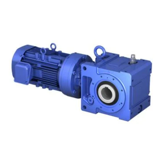
- Page 2 Operation and Maintenance Manual Cyclo ® Bevel Buddybox Manual 13.601.60.005T •May 09...
-
Page 3: Table Of Contents
Cyclo BBB BEVEL BUDDYBOX Speed Reducers and Gearmotors featuring Keyless Taper-Grip® Bushing Operation and Maintenance Manual Table of Contents Taper-Grip® Bushing......1 Parts List . - Page 4 Notes Cyclo ®...
- Page 5 7. Install the torque arm assembly if one is used. 6 X M12 112E7003 8. After mounting is complete, the Cyclo BBB can then be filled with 6 X M12 112E7003 oil. Please follow proper guidelines for oil lubrication. Grease lubri- cated units are pre-filled at the factory.
- Page 6 Parts List General Construction Bevel Gear Case Cyclo ®...
-
Page 7: Taper-Grip Bushing
Parts List continued FIGURE 4. Parts Code Numbers Unit Size Item No. Description Gear Housing AE693LG AE774LG AE695LG AE696LG AE697LG Output Cover BL520LG BL531LG BL542LG BL550LG BL554LG O-Ring 540NG1701-A-G 540NG2101-A-G 540NG2601-A-G 541N5.7-3258G 541N5.7-3757G Oil Seal 531N8511013-G 531N10012513G 531N12015014G 531N14017014G 531N16019016G Hex Head Bolt 001M010R030NG 001M012R030NG... - Page 8 Cyclo Parts List Cyclo Reducer Input Section Single Reduction Item Number Part Number Description High-Speed End Shield 3-03 Bearing D 3-01 High-Speed Shaft — Nipple / Plug — 3-13 Collar — Oil Seal — "C" Face Motor Adapter — Fan Shroud —...
- Page 9 Cyclo Parts List continued Cyclo Reducer Input Section Double Reduction Figure 6. Double Reduction Parts Item Number Part Number Description 3-06 Balance Weight 5-01 Intermediate Shaft w/ Pins — Intermediate Cover 5-03 Bearing G 5-04 Eccentric Cam Assembly 5-02 Bearing F NOTE: The parts listed are a general representation of the components found in a single and double reduction Cyclo.
-
Page 10: Motor Characteristics
Standard Motor Characteristics Motor Characteristics The Cyclo ® BBB gearmotors full load ratings and amper- age can be found below in Figure 7. These ratings are based on the motor’s design values. If additional informa- tion is required, please consult factory. Figure 7. -
Page 11: Brakemotor Characteristics
Brakemotor Characteristics Figure 10. Required Brake Response Action The brakemotor on Cyclo ® BBB gearmotors oper- % Motor Torque Typical ates on a D.C. current supplied by a dual voltage Condition Rating Application Remarks rectifier mounted on the motor conduit box. Rapid Brake Action 100% Machine Tool... - Page 12 Brakemotor Characteristics: Wiring Typical Brakemotor Wiring Illustrated below is a typical brakemotor wiring schematic. Note the rectifier shown is supplied in the motor conduit box. Due to changes in design features, this diagram may not always agree with that on the motor. If different, the motor diagram found inside the conduit box cover is correct. Figure 13.
-
Page 13: Standard Wiring
Figure 17. Normal Brake Action, Low Voltage Motor Rectifier Brake Motor Rectifier Brake Furnished by Furnished by Sumitomo Sumitomo Inverter Inverter Line 230V Line 230V Figure 19. Normal Brake Action, High Voltage Figure 20. Fast Brake Action, High Voltage Motor... -
Page 14: Lubrication
Lubrication Figure 21. Lubrication Type Per Unit Size Input (Cyclo Side) Unit Size Output (Gear Side) Oil lubricated models are not filled Motor Horizontal Motor Vertical with oil prior to shipping. 3A100, 3A105, 3A110, 3A115 Grease Grease 3A120, 3A125, 3B120, 3B125 Before operating, fill the unit with the appro- priate amount of the correct lubricant for the Oil Bath... - Page 15 2C, 2D, and 2E mounted in the Y2 and Y4 positions, please refer to Figure 26 for the proper grease replenishment and C. Sumitomo recommends an oil change every 2500 hours, or six change interval. months, whichever comes first. If a proper preventive mainte- nance program is implemented and maintained, a longer change period may be acceptable.
-
Page 16: Installation
See Fig. 29. Input Speeds NOTE: Parts a through j and n are not provided by Sumitomo. In general terms, the standard input speeds of single reduction units are 1750 and 1165 RPM. - Page 17 Notes Cyclo ®...
- Page 18 Notes Cyclo ®...
- Page 19 Manuel Montes de Oca 6719 Tel: 011-813-6737-2511 • Fax: 011-813-6866-5160 B1606 BMG, Munro Buenos Aires, Argentina Tel: 011-54-11-4765-5332 • Fax: 011-54-11-4765-5517 For Worldwide contact information: www.sumitomodrive.com Manual 13.601.51.005T; Supersedes Manual 13.601.51.004T ©2009 Sumitomo Machinery Corporation of America Printed in USA...
Need help?
Do you have a question about the Cyclo BBB and is the answer not in the manual?
Questions and answers