
Subscribe to Our Youtube Channel
Related Manuals for Fresenius Kabi Link+ Agilia


Summary of Contents for Fresenius Kabi Link+ Agilia
- Page 1 Link+ Agilia Rack System Applicable to software version 3.1 (build D18) Instructions For Use...
-
Page 2: Symbol Descriptions
Symbol Descriptions Symbols used in this document Danger: Warning of an imminent hazard that could result in serious personal injury and/or product damage if the written instructions are not followed. Warning: warning of a potential hazard that could result in serious personal injury and/or product damage if the written instructions are not followed. - Page 3 FSC : Forest Stewardship Council Eco packaging symbol Paper from responsible sources Indicates the authorised representative in Switzerland Symbols only applicable to Link+ Agilia RS232 Cable, Link+ Agilia Nurse call Cable and Link+ Agilia USB Cable Medical Device Unique Device Identifier...
-
Page 4: Table Of Contents
3 Infusion System: Installation and Removal 3.1 Link+ Agilia Preparation..................16 3.2 Link+ Agilia Installation..................16 3.3 Pump Installation and Removal................20 3.4 Remove Link+ Agilia from Fixed Pole, Fixed Rails or Rolling Stand....22 4 Power Management 4.1 Battery - precautions of use.................23 4.2 Battery Operating Mode..................23 4.3 Hard Reset......................23... - Page 5 8 Device Storage 8.1 Precautions for Storage..................37 8.2 Storage and Transport Conditions...............37 8.3 Preparing the Device for Storage................37 8.4 Using the Device after Storage................37 9 Link+ Agilia Quick Check Protocol 10 Troubleshooting 11 Recycling 12 Servicing and Warranty 12.1 Servicing......................43 12.2 Warranty......................44...
-
Page 6: Introduction
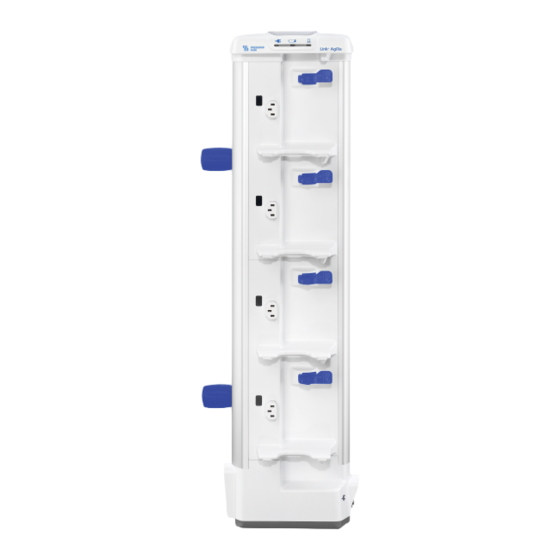
1 Introduction The Link+ Agilia rack system is intended to power 4, 6 or 8 Agilia pumps connected to it. It reduces the number of power cables and improves infusion pump organization at bedside. This is a reusable device that is capable of continuous operation and that can be used daily. -
Page 7: Intended Use
Link+ Agilia in combination with Agilia pumps is intended to be used on the same patient population as Agilia infusion pumps. Link+ Agilia is intended for use on only one patient at a time. It can be reused indefinitely on multiple patients throughout its lifetime. -
Page 8: Clinical Benefits
■ When not in use, the Link+ Agilia device is securely stored. ■ When not in use, the Link+ Agilia Serial or USB Cables are disconnected and securely stored. See Data Communication Cables Installation and Removal on page 25. - Page 9 The Link+ Agilia only stores and processes infusion and device status data. No patient or personnal data are stored and processed by the device. Refer to the Link+ Agilia Technical Manual for more information on how to protect against cycbersecyrity threats, including: ■...
-
Page 10: Description
2.2 Compatible Pumps Do not try to connect pumps other than those recommended. Link+ Agilia has 4, 6 or 8 outlets to power Agilia pumps. These outlets are connected to a functional earth. Link+ Agilia is ONLY compatible with Agilia pumps from Fresenius Kabi sold in your country. - Page 11 Symbol Location Symbol description On lock / release mechanism Press to lock and unlock pumps from Link+ Agilia lever Do not remove the rack from pole or rails if pumps are connected. The rack is heavy when installed with pumps.
-
Page 12: Cap User Interface
2.4 Cap User Interface Legend Alarm centralisation LED Power status LED Battery status LED System status LED 2.5 Side View with Power Plug Legend Power status indicator Power connection... -
Page 13: Side View With Connector Panel
2.6 Side View with Connector Panel Legend Wired network connector Wired network status LED Hard reset button Not used (for future release) USB PC status LED USB PC connector Not used (for future release) Not used (for future release) RS232 Serial communication connector RS232 Serial communication Nurse call status LED... -
Page 14: Back View (Device Identification Label)
Symbol Description Mac address Nurse call connector Serial connector Hard reset button Universal Serial Bus connector Direct Current (DC) Electrostatic sensitive device 2.8 Back View (Device Identification Label) Legend Upper pole clamp Lower pole clamp Device Identification Label Symbol Symbol description Clamps must be mounted outside this area... -
Page 15: Packaging
■ 1 Link+ Agilia for 4, 6 or 8 pumps; ■ 1 User Information Document; ■ 2 clamps to mount and fasten Link+ Agilia on a pole, vertical or horizontal rails or any recommended accessories; ■ 1 tool to fasten clamps on Link+ Agilia;... -
Page 16: Infusion System: Installation And Removal
3. Adjust / rotate clamps to mount rack on pole or on rails. 4. Fasten pole clamps firmly to avoid movement. 3.2 Link+ Agilia Installation WARNING When the pump is installed onto Link+ Agilia, make sure that it is correctly plugged in (hook clipped) so as to prevent the pump from falling. - Page 17 ■ Always use the 2 rack clamps to ensure the stability of the device when mounted on a pole or on a rail. CAUTION Do not install Link+ Agilia with pumps already mounted on it to avoid any risk of traumatic injuries. CAUTION The Agilia pumps must be located at ±...
- Page 18 Mechanical specifications for locking clamps: ■ Pole: diameter: from 16 to 42 mm. depth: 10 mm maximum. ■ Rail: diameter: from 16 to 42 mm. depth: 10 mm maximum. 3.2.2 Installation on a Rolling Stand CAUTION When installed on a Rolling stand, make sure it can accommodate the weight of the pumps and accessories.
-
Page 19: Powering On And Off
The system status LED located on the upper side switches from yellow to green when the system is ready. The device powers OFF automatically when: ■ power is disconnected (device is operating on battery), AND ■ no more pumps are powered ON or installed on the Link+ Agilia for at least 30 minutes. -
Page 20: Pump Installation And Removal
WARNING Link+ Agilia must not be used if a push button remains depressed (power ON) when no pump is present. This must be checked before each pump installation and removal. - Page 21 'click') as indicated on the auto locking mechanism. WARNING If the pump is incorrectly plugged onto Link+ Agilia, it can fall and cause patient injuries. 4. When the rack is powered by AC power, check pump display to confirm power display light is ON and listen to the audio pump signal.
-
Page 22: Remove Link+ Agilia From Fixed Pole, Fixed Rails Or Rolling Stand
3. Carefully remove the pump from the slot. 4. Store the pump according to the pump's instructions for use. 3.4 Remove Link+ Agilia from Fixed Pole, Fixed Rails or Rolling Stand 1. Unlock and remove all mounted Agilia pumps by pushing on the release mechanism. -
Page 23: Power Management
4.2 Battery Operating Mode Link+ Agilia is provided with an internal battery that automatically provides power to Link+ Agilia for a minimum period of 1 hour in case of power failure or disconnection from mains power supply. For additional information about battery status indications, refer to Signaling on page 30. - Page 24 Legend Hard reset button This button is for maintenance purpose only. Please refer to the technical manual for additional details.
-
Page 25: Data Communication Cables Installation And Removal
5.1 Network Cable Connection and Removal WARNING The Link+ Agilia visual alarm system is not intended to be a real time monitoring accessory. An up to 10 seconds delay may occur between the alarm triggering on the pump and on the Link+ Agilia. - Page 26 5.1.1 Connecting Link+ Agilia Directly to a Computer or a Wired Hospital Network 1. Plug one side of the Ethernet network cable on Link+ wired network connector indicated. 2. Plug the other side to the computer Ethernet connector or into the Hospital network wall socket.
-
Page 27: Serial Communication Connection And Removal
5.2 Serial Communication Connection and Removal Link+ Agilia can be connected to a third party system using a serial interface and a serial cable to exchange data. This cable must be ordered separately. Refer to Ordering Information on page 45. -
Page 28: Usb Connection And Removal
, remove the serial cable from Link+ by pulling the cap of the plug (see picture). 5.3 USB Connection and Removal Use the Link+ Agilia USB Cable accessory. This cable must be ordered separately. Refer Ordering Information on page 45. - Page 29 ■ Check the insulation safety requirements of the connected system. ■ Nurse call signaling levels must comply with Safety Extra Low Voltage (SELV) for Link+ Agilia rack. Extra Low Voltage is specified 24 V DC, and must not exceed this value under normal conditions, and under single-fault conditions, including earth faults in other circuits.
-
Page 30: Signaling
CAUTION The Alarm centralisation LEDs are not related to the Link+ Agilia status. The Link+ Agilia provides the user with visual centralisation of the alarms of all connected pumps. The Alarm centralisation LEDs are located at the top of the device ■... -
Page 31: Operational Mode Indications
6.3 Power Supply, Battery and System Displays and Status The Link+ Agilia provides the user with visual information about the power supply, the battery and the system status indicated by a specific display located at the top of the device. - Page 32 Battery and power supply absent System status LED Event Color Status Link+ Agilia internal software is booting YELLOW Link+ Agilia internal software is running GREEN Link+ Agilia internal software error Reset button is pressed, system is restarting FIX during start...
-
Page 33: Connector Displays And Status
2.5 Hz Nurse call connector display and status The Link+ Agilia provides the user with a visual indication of the availability of a connected pump signal for communication to an external nurse call system. The display is located on the connector panel as indicated above. -
Page 34: Cleaning And Disinfection
The following warnings are provided to protect staff against electric shock, biological contamination and protect the device from damage that can cause the device to malfunction. Link+ Agilia is not intended to be sterilized. Sterilization may result in damage to the device. CAUTION The following actions may damage the device and make it unusable: ■... -
Page 35: Cleaning Instructions
1. With a fresh ready-to-use wipe, remove gross filth and heavy soil loads. Then thoroughly clean all exposed surfaces (plastic and metal housing...) of Link+ Agilia from top to bottom. Be sure to also thoroughly wipe down screw clamps, levers and pump power inlets. - Page 36 7.4.3 Cleaning and Disinfection Instructions for accessories At room temperature (20 to 25°C): 1. For cleaning, with a fresh ready-to-use wipe, wipe down accessories. Allow the accessories to completely dry. 2. For disinfection, repeat the step 1.
-
Page 37: Device Storage
CAUTION If the Link+ Agilia is not used during 2 months or more, it is recommended to remove the battery from it. If the battery remains in the device during such a long period, its autonomy may be impaired or it may become unusable. If removing the battery is impossible, contact your biomedical department. - Page 38 INFORMATION It is recommended that the quick check protocol is performed after installing it for use on a new patient.
-
Page 39: Link+ Agilia Quick Check Protocol
9 Link+ Agilia Quick Check Protocol The following protocol provides the user with a quick check guide to ensure that Link+ Agilia system is functional. It is recommended that this protocol be performed after installation and before use of the device on a new patient. - Page 40 Test description Expected results Compliant Program the pump and A visual and audible medium priority alarm is displayed on generate a medium priority pump. alarm (e.g., occlusion A visual alarm is blinking in yellow on the Link+ alarm prealarm on an Agilia large centralisation display (on the top).
-
Page 41: Troubleshooting
No sound is audible from pump when ■ Check power status indicator mounted to Link+ Agilia ■ Check Link+ Agilia is connected to AC power supply ■ Contact your biomedical department or Fresenius Kabi sales representative Data communication cables cannot be ■... -
Page 42: Recycling
They must be collected separately and disposed of according to local regulations. INFORMATION For more information on waste processing regulations and dismantling, please contact your Fresenius Kabi sales representative or local distributor. -
Page 43: Servicing And Warranty
■ When replacing components, only use spare parts from Fresenius Kabi. The life cycle of Link+ Agilia is 10 years provided that the maintenance is properly performed as described above. 12.1.3 Quality Control A regular quality control check (not included in the guarantee) consists of various inspection operations listed in the technical manual. -
Page 44: Warranty
■ the internal battery of the device must not have been replaced by a battery other than that specified by the manufacturer. If one or more of these conditions have been violated, Fresenius Kabi will prepare a repair estimate covering all required parts and labor. -
Page 45: Ordering Information
Link+ Agilia RS232 Cable Cable for Link+ Agilia serial interfacing Z073601 Link+ Agilia Nurse call cable Cable to connect Link+ Agilia to an external nurse Z073602 call back system (unterminated cable) Crossover network cable Cable for Link+ Agilia configuration (delivered with... - Page 46 Mounting systems Rolling Stands are available as accessories. See Installation on a Rolling Stand on page...
-
Page 47: Technical Specifications
Max weight: 6.7 kg AC Power Input Specifications Function Primary power source for Agilia power outlets and for internal electronics of Link+ Agilia Connector Standard appliance inlet IEC type C14 - male - 3 poles Power supply 100 V to 240 V AC / 50/60 Hz... -
Page 48: Data Communication Connectors
7.2 V 2.2 Ah - Lithium Ion rechargeable battery ■ 7.34 V 2.75 Ah - Lithium Ion rechargeable battery To identify the type of battery installed, refer to the technical manual of Link+ Agilia. Battery autonomy 1 hour minimum Self protections... -
Page 49: Compliance With Standards
RS232 serial communication connector specifications Function System management, PC, PDMS, or maintenance connection Connector ADAM TECH shielded circular female connector, 3 pins Indicator Blue LED Compatibility RS232 levels, serial asynchronous, half duplex Insulation 1.5 kV insulation from external system + provides double insulation (4 kV) from mains Speed 115.2 kb/s max. - Page 50 ■ Agilia power outlets are wired on internal functional earth to reduce residual current that may disturb ECG or EEG devices. ■ The outer enclosure of Link+ Agilia is not higher than +48 °C. This temperature was validated for skin contact, and contact duration between 1 and 10 minutes.
-
Page 51: Guidance And Manufacturer's Declaration On Emc
Excluding the case described in this manual, Link+ Agilia operation must be systematically checked by a qualified operator, if the Link+ Agilia is installed in the vicinity of the other electrical devices. Points (for example screws) and surfaces that are accessible only by maintenance staff also require precautions. -
Page 52: Electromagnetic Compatibility And Interference Guidance
The best precaution is preliminary user discharge on a grounded metal object such as a rail, a pole or a metal part located at the rear of the Link+ Agilia. For maintenance operation performed on Link+ Agilia, place the device on a conductive working surface, and wear a special ESD conductive wristband. -
Page 53: Emc And Essential Performances
■ increase the separation between Link+ Agilia and the patient or disruptive equipment; ■ plug Link+ Agilia into an outlet on a different circuit from the one to which the patient or disruptive equipment is connected; ■ in any case, whatever the context, the user should conduct interoperability testing in a real situation to find the correct setup and location. - Page 54 Electromagnetic Immunity WARNING ■ Link+ Agilia and its accessories are intended to be used in the electromagnetic environments specified below. ■ The customer or the user of the Link+ Agilia should ensure that it is used in such environments. Immunity Compliance...
- Page 55 15.4.3 Table 4 - Guidance and Manufacturer's Declaration - Electromagnetic Immunity WARNING ■ Link+ Agilia and its accessories are intended to be used in the electromagnetic environments specified below. ■ The customer or the user of the Link+ Agilia should ensure that it is used in such environments.
- Page 56 RF transmitters, an electromagnetic site survey should be considered. If the measured field strength in the location where Link+ Agilia is used exceeds the applicable RF compliance level above, Link+ Agilia should be observed to verify normal operation. If abnormal performance is observed, additional measures may be necessary, such as reorienting or relocating Link+ Agilia, or installing magnetic shielding.
- Page 57 ■ The device should not be used next to other equipment. If adjacent use is necessary, observe the device to verify that it operates normally in the configuration in which it will be used (Link+ Agilia with a AC power cord, an RS232 cable).
- Page 58 3 V/m, used no closer to any to IEC 301489-1 and 2.7 GHz to 6 GHz part of the IEC 30189-17: Link+ Agilia, including 3 V/m, cables, than the 2.7 GHz to 6 GHz recommended separation distance calculated from the...
- Page 59 930 MHz, PM217 18 Hz, 28V/m part of the 1720 MHz, PM 217 Hz, 28 V/m 1720 MHz, PM 217 Hz, 28 V/m Link+ Agilia, including 1845 MHz, PM 217 Hz, 28 V/m 1845 MHz, PM 217 Hz, 28 V/m cables, than the...
- Page 60 61000-4-8 make sure it is lower than the compliance level. If the measured field in the location where the Link+ Agilia is used exceeds the applicable magnetic field compliance level above, the Link+ Agilia should be observed to verify normal operation.
- Page 61 For very long (> than battery autonomy) interruptions of electricity power supply, the Link+ Agilia must be powered from an external Uninterruptible Power Supply (UPS). Note: Ut is the a/c mains voltage prior to application of the test level.
-
Page 62: Glossary Of Terms
16 Glossary of Terms Term Description Ampere Alternating Current Agilia Range of infusion pumps manufactured by Fresenius Kabi Ampere hour CISPR International Special Committee on Radio Interference CT Scan Computed Tomography Direct current DECT Digital Enhanced Cordless Telecommunications DERS Dose Error Reduction Software... - Page 63 Term Description Volt Ampere...
-
Page 67: Release Notes
This document may not be reproduced in whole or in part without the written consent of Fresenius Kabi. Agilia® is a registered trademark in the name of Fresenius Kabi in selected countries. - Page 68 Local contacts for servicing Fresenius Kabi AG Fresenius Vial S.A.S Else-Kröner-Str. 1 Le Grand Chemin 61352 Bad Homburg, GERMANY 38590 Brézins - FRANCE Tel.: +49 (0) 6172 / 686-0 www.fresenius-kabi.com...
Need help?
Do you have a question about the Link+ Agilia and is the answer not in the manual?
Questions and answers