Fresenius Kabi Agilia Link Instructions For Use Manual
Rack system
Hide thumbs
Also See for Agilia Link:
- Instructions for use manual (46 pages) ,
- Instructions for use manual (82 pages)
Table of Contents
Advertisement
Advertisement
Table of Contents

Related Manuals for Fresenius Kabi Agilia Link


Summary of Contents for Fresenius Kabi Agilia Link
- Page 1 Agilia Link Rack System INSTRUCTIONS FOR USE...
- Page 2 Symbol Descriptions Refer to the Instructions For Use General warning sign Not for use in residential areas Operating instructions CE mark Product reference / part number Product serial number Name and address of the manufacturer Name and address of the manufacturing...
-
Page 3: Table Of Contents
11 3.1 Agilia Link Preparation..................11 3.2 Agilia Link Installation..................11 3.3 Pump Installation and Removal................14 3.4 Remove Agilia Link from Fixed Pole, Fixed Rails or Rolling Stand....16 4 CLEANING AND DISINFECTION 18 4.1 Prior to Cleaning and Disinfection..............18 4.2 Prohibited Cleaning and Disinfection Agents.............18... - Page 4 8 SERVICING AND WARRANTY 24 8.1 Servicing......................24 8.2 Warranty......................25 9 ORDERING INFORMATION 26 9.1 Agilia Link Packaging..................26 9.2 Accessories and Options..................26 10 TECHNICAL SPECIFICATIONS 27 10.1 Technical Data....................27 10.2 Guidance and Manufacturer’s Declaration on EMC.........28 11 GLOSSARY OF TERMS 31...
-
Page 5: Introduction
1 Introduction The Agilia Link rack system is intended to power 4, 6 or 8 Agilia pumps connected to it. It reduces the number of power cables and improves infusion pump organization at bedside. This is a reusable device that is capable of continuous operation and that can be used daily.... -
Page 6: Contraindications
1.6 Use Environment Agilia Link is intended for use in healthcare facilities, under the supervision of trained healthcare personnel. Agilia Link must be used in the following operational conditions to ensure proper performance:... -
Page 7: Description
The system of Agilia Link is composed of the following elements: ■ 1 Agilia Link rack able to stack 4, 6 or 8 Agilia pumps with a power cord; ■ up to 8 Agilia pumps with their respective accessories, disposables and documents.... -
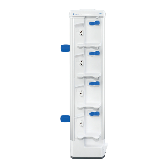
Page 8: Side View With Power Plug
Symbol Location Symbol description Do not remove the rack from pole or rails if pumps are connected. The rack is heavy when installed with pumps. On right and left sides Remove pumps first, before removing the rack from poles or rails. Unscrew lower pole clamp first.... -
Page 9: Back View (Device Identification Label)
2.7 Packaging The Agilia Link packaging contains the following elements: ■ 1 Agilia Link for 4, 6 or 8 pumps; ■ several Instructions for Use manuals (depending on the part number of your device); ■ several power cords (depending on the part number of your device);... -
Page 10: Recycling
■ 2 clamps to mount and fasten Agilia Link on a pole, vertical or horizontal rails or any recommended accessories; ■ 1 tool to fasten clamps on Agilia Link. INFORMATION If the packaging contents are incomplete or damaged, contact your Fresenius... -
Page 11: Infusion System: Installation And Removal
3.2 Agilia Link Installation INFORMATION ■ Do not install Agilia Link on a pole or rails if pumps are already mounted to Agilia Link. ■ Agilia Link is designed to be mounted onto a fixed pole and fixed rails or... - Page 12 Refer to Agilia Link Quick Check Protocol on page 22. For sensitive patients, it is recommended to install Agilia Link behind the patient’s bed or incubator, to prevent discomfort. 3.2.1 Installation on a Fixed Pole or Fixed Rails...
- Page 13 INFORMATION Mechanical specifications for locking clamps: ■ Pole: diameter: from 16 to 42 mm. ■ Rail: height: from 16 to 42 mm. ■ Depth: 10 mm maximum. 3.2.2 Installation on a Rolling Stand WARNING ■ Link 8 Agilia is only compatible with New MultiChannel Rolling Stand (Part number Z073160) and Twin Link Rolling Stand (Part number Z073170)....
-
Page 14: Pump Installation And Removal
■ The power outlet must remain accessible at all times to allow emergency power supply disconnection. ■ If the power cord is not correctly plugged on Agilia Link, the pumps will work on battery creating risks of premature stop if battery alarm is not... - Page 15 ■ Agilia Link must not be used if a push button remains depressed (power ON) when no pump is present. This must be checked before each pump...
-
Page 16: Remove Agilia Link From Fixed Pole, Fixed Rails Or Rolling Stand
WARNING If the pump is incompletely plugged onto Agilia Link, it can fall and cause patient injuries. 4. When the rack is powered by AC power, check pump display to confirm power display light is ON and listen to the audio pump signal.... - Page 17 2. Remove power cable. 3. Unscrew the lower clamp first. 4. Next unscrew the upper clamp and remove the rack from the pole or rails. 5. Store the rack in a suitable place. Refer to Device Storage on page 21 for additional information....
-
Page 18: Cleaning And Disinfection
The following warnings are provided to protect staff against electric shock, biological contamination and protect the device from damage that can cause the device to malfunction. Agilia Link is not intended to be sterilized. Sterilization may result in damage to the device. WARNING... - Page 19 1. With a fresh ready-to-use wipe, remove gross filth and heavy soil loads. Then thoroughly clean all exposed surfaces (plastic and metal housing...) of Agilia Link from top to bottom. Be sure to also thoroughly wipe down screw clamps, levers and pump power inlets....
- Page 20 4.4.3 Cleaning and Disinfection Instructions for accessories At room temperature (20 to 25°C): 1. For cleaning, with a fresh ready-to-use wipe, wipe down accessories. Allow the accessories to completely dry. 2. For disinfection, repeat the step 1. 20...
-
Page 21: Device Storage
5.3 Preparing the Device for Storage Prepare the device for storage as follows: 1. Be sure that pumps connected to Agilia Link are not being used on a patient. 2. Power the pump OFF and remove the disposable. 3. Remove connected pumps.... -
Page 22: Agilia Link Quick Check Protocol
6 Agilia Link Quick Check Protocol The following protocol provides the user with a quick check guide to ensure that Agilia Link system is functional. It is recommended that this protocol be performed after installation and before use of the... -
Page 23: Troubleshooting
Contact your biomedical department or Fresenius Kabi sales representative No sound is audible from pump when ■ Check power status indicator mounted to Agilia Link ■ Check Agilia Link is connected to AC power supply ■ Contact your biomedical department or Fresenius Kabi sales representative 23... -
Page 24: Servicing And Warranty
Internal inspection of the device requires compliance with special procedures to avoid damage to the device. ■ When replacing components, only use spare parts from Fresenius Kabi. The life cycle of Agilia Link is 10 years provided that the maintenance is properly performed as described above. INFORMATION... -
Page 25: Warranty
Fresenius Kabi sales representative. 8.2 Warranty 8.2.1 General Warranty Conditions Fresenius Kabi guarantees that this product is free of material and workmanship defects during the period defined by the accepted sales conditions, except for the batteries and the accessories. 8.2.2 Limited Warranty... -
Page 26: Ordering Information
■ ONLY use recommended accessories and options delivered with the device. ■ Additional power cords and 'Instructions for Use' documents must be ordered separately. Contact your Fresenius Kabi sales representative for ordering. 9.1 Agilia Link Packaging Contact your Fresenius Kabi sales representative for ordering.... -
Page 27: Technical Specifications
Standard appliance inlet IEC type C14 - male - 3 poles Power supply 100 V to 240 V AC / 50/60 Hz Maximum power Agilia Link 4: 60 VA (with pumps) Agilia Link 6: 90 VA Agilia Link 8: 120 VA... -
Page 28: Guidance And Manufacturer's Declaration On Emc
Do not use Agilia Link in MRI, CT Scan or X- Ray environments. Excluding the case described in this manual, Agilia Link operation must be systematically checked by a qualified operator, if the Agilia Link is installed in the vicinity of the other electrical devices. 28... - Page 29 The best precaution is preliminary user discharge on a grounded metal object such as a rail, a pole or a metal part located at the rear of the Agilia Link. For maintenance operation performed on Agilia Link, place the device on a conductive...
- Page 30 ■ increase the separation between Agilia Link and the patient or disruptive equipment; ■ plug Agilia Link into an outlet on a different circuit from the one to which the patient or disruptive equipment is connected; ■ in any case, whatever the context, the user should conduct interoperability testing in a...
-
Page 31: Glossary Of Terms
11 Glossary of Terms Term Description A Ampere AC Alternating Current Agilia Range of infusion pumps manufactured by Fresenius Kabi Ah Ampere hour CISPR Special International Committee on Radio Interference DECT Digital Enhanced Cordless Telecommunications ECG Electrocardiogram EEG Electroencephalogram EMC... - Page 32 This document may not be reproduced in whole or in part without the written consent of Fresenius Kabi. Agilia is a registered trademark in the name of Fresenius Kabi in selected countries....
Need help?
Do you have a question about the Agilia Link and is the answer not in the manual?
Questions and answers