
Related Manuals for EG4 GRIDBOSS


Summary of Contents for EG4 GRIDBOSS
- Page 1 E G 4 G R I D B O S S ® U S E R M A N U A L ©2024 EG4 ® ELECTRONICS, LLC. ALL RIGHTS RESERVED. VERSION 1.1.2 | INFORMATION SUBJECT TO CHANGE WITHOUT NOTICE. MODEL #: MI-200-2P-HYB-AW-01...
-
Page 2: Table Of Contents
MOUNT THE UNIT ....................10 INSTALL BREAKERS ....................13 INSTALL CABLES ...................... 17 CONFIGURE THE HYBRID INVERTERS ............... 28 CONFIGURE GRIDBOSS: ..................29 VERIFY CONFIGURATION ..................31 SYSTEM OPERATION & CONFIGURATION EXAMPLES ......... 33 HYBRID INVERTERS ....................33 GENERATOR ......................35 MANUAL BYPASS MODE .................. -
Page 3: Technical Specifications
1. TECHNICAL SPECIFICATIONS GRID NOMINAL AC VOLTAGE 120/240VAC (L1/L2/N required) FREQUENCY 60 Hz MAXIMUM CURRENT 200A 22kAIC with 200A Eaton breaker (model: CSR25K) SERVICE ENTRANCE RATED GENERATOR NOMINAL VOLTAGE 120/240VAC (L1/L2/N required) FREQUENCY 60 Hz MAXIMUM CURRENT 125A NON-BACKUP NOMINAL VOLTAGE 120/240VAC (L1/L2/N required) 60 Hz FREQUENCY... -
Page 4: Abbreviations
2. ABBREVIATIONS • AWG – American Wire Gauge • In-lbs. – Inch Pounds A – Amps kW – Kilowatt • • Ah – Amp hour(s) kWh – Kilowatt-hour • • AC – Alternating Current LCD – Liquid Crystal Display • •... -
Page 5: Safety
“off” or “open” position before installing or working on the inverter. Use a voltmeter to confirm there is no voltage present to avoid electric shock. 2. Do not open the internal GridBOSS cover while it is operating to avoid electric shock and damage from live voltage and current within the system. - Page 6 5. The installer should consider the safety of future users when choosing the correct position and location for GridBOSS as specified in this manual. 6. Keep children from touching or misusing the inverter and relevant systems.
-
Page 7: Packing Lists
4. PACKING LISTS The items listed below will arrive with each product shipment: GridBOSS (x1) Mounting Bracket Neutral-Ground L-Bracket (x2) (x1) Bonding Jumper (x1) Waterproof Cover Two Pole • M63 (x8) Breaker cover (x2) Extra fuse (x2) Breaker (x8)* G-M50 (x3) •... -
Page 8: Product Dimensions
5. PRODUCT DIMENSIONS U.S. NOMINAL TRADE SIZE ACTUAL SIZE 1/2 in. 0.88 in. (22.2 mm) 3/4 in. 1.12 in. (28.5 mm) 1 in. 1.38 in. (35 mm) 1 1/4 in. 1.73 in. (44 mm) 1 1/2 in. 1.99 in. (50.5 mm) 2 in. -
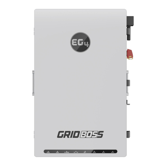
Page 9: Product Overview
IMPORTANT The breakers displayed in the image above are the maximum supported sizes for each port. The maximum allowed total output amperage is set at 200 amps. If the current draw exceeds 200A, GridBOSS will begin to limit load output... -
Page 10: Installation
7.1 MOUNTING AREA & SPACING REQUIREMENTS Follow the requirements listed below for system installation: 1. The mounting wall must be strong enough to bear the weight of all equipment (GridBOSS, inverters, wall mounted batteries, etc). 2. Maintain the minimum clearances of 3 in. (76 mm) on all sides. - Page 11 0 in. (0 mm) 5 3/16 in. (135 mm) GridBOSS is designed to be wall 2 3/8 in. mounted using the included wall (60 mm) mount bracket.
-
Page 12: Recommended Tools
Socket Set Masonry Bit 7.3 MOUNT THE UNIT 1. Select a suitable location to install the GridBOSS as described in section 7.1. 2. Use the wall mounting bracket as a template to mark where the screws will be installed. When installing the wall bracket to studs, verify the marks for the screws are centered over a stud. - Page 13 6. Temporarily mount the L-bracket to the side of the GridBOSS (located at the bottom, one on each side). Mark a hole on the wall based on the hole location inside the L-bracket. Repeat this step for both sides.
- Page 14 3. Repeat this step for both sides. 8. Attach the L-brackets (one on each side) to the GridBOSS and to the wall using the correct hardware. Once the bracket is secure, the wall installation is complete.
-
Page 15: Install Breakers
7.4 INSTALL BREAKERS This section provides the steps to install the breakers that are included with the GridBOSS. The front inner black cover must be removed to obtain access to each breaker connection area. To expose the connection areas, open the front door by releasing the clasps on the right side of the unit. Next, remove the four screws as identified in the image below and then carefully remove the inner black cover by lifting it out of the chassis. - Page 16 When installing a breaker, hold the breaker at an angle and place the bottom slot of the breaker on the metal bracket inside the GridBOSS chassis. Then pivot the breaker towards the chassis until the top of the breaker snaps onto busbar blades.
- Page 17 Optional Main Breaker Installation: 1. Remove the internal orange cover by first removing the two nuts using a 7mm socket and the six screws using a Phillips screwdriver. Then lift the cover out of the unit. 2. With the inside cover removed, locate the lugs for both line 1 and line 2 (outlined with dashed line).
- Page 18 3. Before installing the breaker, adjust the position of the insulation sheet by moving the end to the right side. 4. Install the Eaton (model (CSR2200N) CSR25K) breaker by sliding it into place, aligning the bolt holes in the breaker lugs to the holes on the busbar.
-
Page 19: Install Cables
Use the information in this section for guidance on connecting the AC wiring. Using a multimeter, verify each wire is not carrying voltage before making the connection to the GridBOSS. If the inner cover needs to be removed, see the previous section. -
Page 20: System Ground
The ground busbar supports connecting GridBOSS to the building's equipment grounding system and to the building's grounding electrode system if using GridBOSS as service entrance equipment. The ground cable should be installed first to provide a solid ground during the wiring installation process. - Page 21 The unit ships with a neutral-ground bonding jumper (bracket) that connects the ground busbar to the neutral busbar. This should only be attached if GridBOSS is the first service disconnect, as there can only be one neutral bond connection in the electrical system.
- Page 22 1/4-inch hex GENERATOR PORT GridBOSS can utilize supplemental 240VAC generator power for backup and battery charging in the case of a grid failure. The generator port can supply power to the backup port, the hybrid ports, and configured smart ports when the grid power goes down. To support automatic generator startup, the GridBOSS has a 2-wire start/stop terminal for controlling 2-wire start capable generators.
-
Page 23: Generator Operation
1 is closed. When start/stop relay 1 is closed, GridBOSS must wait until the generator is able to supply stable output power. This wait time is configured using the generator warm-up time setting in the EG4 Monitor Center. - Page 24 CAUTION The non-backup port is not controlled by a breaker or relay and will always receive current if GridBOSS is supplied with grid input. WARNING The non-backup port does not have built in overcurrent protection at the port output.
- Page 25 BACKUP LOADS PORT The backup port provides power to any panel the needs to be backed up by the EG4 energy storage system. This could be the home's main breaker panel, a critical loads subpanel, or any combination of main panels and subpanels.
- Page 26 GridBOSS hybrid ports connect to supported EG4 hybrid inverters. When cabling the AC connection to ® the hybrid inverter, only connect the inverter’s grid port to the GridBOSS hybrid port. See the chart below for supported EG4 hybrid inverters. WARNING: The only inverters that can be connected to the hybrid ports are the 12kPV, 18kPV and FlexBOSS21.
- Page 27 NOTE When operating a hybrid inverter with GridBOSS, smart port functionality is moved from the hybrid inverter to GridBOSS. All devices that connect through a smart port must be cabled directly to a GridBOSS smart port. Select GridBOSS in EG4 ®...
- Page 28 RAPID SHUTDOWN & ESS DISCONNECT GridBOSS supports a rapid shutdown system that complies with 2017 and 2020 NEC 690.12, and ESS Disconnect that complies with NEC 706.15 requirements. The rapid shutdown switch on the right side of GridBOSS, when used, will initiate total system shutdown including the inverters, supported batteries, and PV (if properly equipped).
- Page 29 REPLACE CABLE BOX COVER Before replacing the cable box cover, remove any knockouts that cover a port where a breaker was installed. The knockouts are designed to be moved back and worth until the small connection point between the knockout and the cover is broken and the knockout can be removed. Install the grid and generator cover plate if breakers are not installed.
-
Page 30: Configure The Hybrid Inverters
If using more than one inverter, verify they are set up in a functioning parallel configuration. • • Do Not connect the inverter’s load port to GridBOSS. The inverter’s load port must remain in the off position. Do Not cable anything to the inverter’s generator port (if equipped). The inverter’s generator •... -
Page 31: Configure Gridboss
• All GridBOSS breakers are in the off position. • If a main breaker is not installed in the GridBOSS, verify the source providing power to the • GridBOSS is in the off position. If the non-backup port is cabled to an electrical panel, verify the breaker in the panel is in the •... - Page 32 GridBOSS with Two Hybrid Inverters Slave Inverter GridBOSS Master Inverter GridBOSS with Three Hybrid Inverters Subordinate Subordinate Slave Inverter Master Inverter Master Inverter Slave Inverter GridBOSS GridBOSS Inverter 1 Inverter 2 2. Power on the inverter(s), starting with the master in a parallel configuration. The inverters should only be powered by the battery or battery bank.
-
Page 33: Verify Configuration
FlexBOSS will require the use of the EG4 Monitor Center or mobile app. 7. Enable grid input to the GridBOSS by turning on the grid breaker (if equipped) or by turning on the breaker providing grid access. - Page 34 Role: Verify GridBOSS has only ONE master inverter. The master inverter should be set to • “1 Phase primary” and all other inverters should be set to “Slave”. Remember to press the “Auto Detect Phase” reset button if any changes are made to the parallel settings.
-
Page 35: System Operation & Configuration Examples
8. SYSTEM OPERATION & CONFIGURATION EXAMPLES GridBOSS must be set up with at least one powered input in order to power up and be ready for operation. The input can be from the grid, a hybrid inverter, or from a generator. GridBOSS acts as a power distribution unit that controls the flow of power using internal relays and software. - Page 36 Smart Ports. This includes smart ports and the non-backup loads port. Inverter Settings: Application: Power Backup: Enable Grid Sell Back: Enable Fast Zero Export: Disable Off-Grid Mode: Disable Charge: AC Charge: Enable or Disable based on need Discharge: Forced Discharge Enable: Enable or Disable GridBOSS Settings: No changes required...
-
Page 37: Generator
8.2 GENERATOR In this example, a generator has been added to the GridBOSS to power the backup loads and to supplement charging the batteries, if needed. The generator breaker and the generator relay are in the closed position allowing current to flow to the backup loads. Generator output could assist in charging the batteries as long as the proper settings are configured, and the loads are small enough leaving the extra power from the generator to charge the batteries. -
Page 38: Manual Bypass Mode
8.3 MANUAL BYPASS MODE In this scenario, all the relays in GridBOSS are bypassed allowing grid current to flow directly to the backup loads port powering the critical loads panel. The bypass mode was set up to support critical loads in the unforeseen circumstance the GridBOSS needs to be bypassed. The non-backup loads port also receives power from the grid when in bypass mode. -
Page 39: Smart Loads
NOTE: Smart port functionality is not supported at the hybrid inverter when attached to a GridBOSS. All devices that are powered by a smart port must be connected directly to a GridBOSS smart port. See the next page for example configurations. - Page 40 Example Configurations: 1. Always On: The following examples show how to configure a smart load to be always enabled. This can be done in two ways either by using the “Grid Always On” setting, or by using the “Time” and “SOC/Voltage” settings. Using “Grid Always On” enables the smart port when there is grid input.
-
Page 41: Ac Coupling
AC coupled device is UL1741, UL1741SA, or UL1741SB certified. Uncertified devices may cause hardware damage to the equipment. NOTE: Smart port functionality is not supported at the inverter generator port when attached to a GridBOSS. All AC coupled devices must be connected directly to a GridBOSS smart port. - Page 42 In this example, AC coupling will be used as supplemental power to the backup port and to assist with charging the batteries. Once the batteries are fully charged, AC coupled power will continue to assist with powering loads since only time was used to close the smart port relay. GridBOSS Settings: Inverter Settings: MIDBOX:...
-
Page 43: Remote System Management
Once the dongle is physically installed to the chassis, the dongle serial number and PIN need to be added to an EG4 user account to set up remote connectivity. New EG4 users will need to create a new account. Users can also add GridBOSS to an existing account, which is shown in section 9.2. -
Page 44: Create New Account
9.1 CREATE NEW ACCOUNT Using EG4 Monitor Center ® 1. Using a web browser, connect to “monitor.eg4electronics.com” and select “Register”. 2. Complete the registration form as shown below. Contact the distributor for the customer code. The dongle serial number (SN) and dongle PIN can be found on the sticker attached... - Page 45 3. Once the registration is complete, return to the EG4 Monitor Center web page and log in ® using the username and password created during the registration process. Using the Mobile App 1. Download the “EG4 Monitor” app for iOS or Android. After installation is complete, open the ®...
-
Page 46: Existing Accounts
9.2 EXISTING ACCOUNTS When an EG4 account already exists, newly added EG4 hardware that uses a dongle can be added ® to the existing account. This can be completed using the EG4 Monitor Center or the mobile app. ® Using EG4 ®... - Page 47 Using the Mobile App 1. Open the “EG4 Monitor” app and log in using an existing name and password. ® 2. Select the back arrow in the upper left corner of the screen. 3. Select “Add Dongle”. 4. Scan or enter the dongle information located on the dongle sticker, then select “Add...
-
Page 48: Eg4 ® Monitor Center
Monitor Center when viewing GridBOSS. The main page will display ® GridBOSS as a horizontal green bar with various items above and below the bar. All AC input and output information displayed here shows what is directly connected to the GridBOSS' ports. All DC input and output information is pulled from the hybrid inverter. -
Page 49: Maintenance Tab
10.1 MAINTENANCE TAB This section describes the settings for each area within GridBOSS. As a best practice, always start with selecting the “Read” button at the top of the maintenance page. This will refresh the settings page displaying the currently set values for each option. - Page 50 Before changing a smart port's mode, disable the port so that it does not immediately start to function. This allows the port settings to be configured while providing protection for the whole system. After fully configuring the port options, enable the port as the last step. SMART LOADS This section describes the various smart load settings.
- Page 51 Basic: The smart load is configured using time and SOC/voltage. The port will be active if within the set time period and when the SOC or voltage is above the specified start value. The port will be disabled if outside the specified time period, and the end SOC/voltage is below the set value. Both the SOC/voltage and time values must be set in order for the smart load to operate.
- Page 52 (powered on) when the hybrid inverter’s “Export to Grid” setting is enabled, and when the time period logic is met. GridBOSS will also open the AC couple port relay when the hybrid inverter’s “Export to Grid” is disabled to avoid providing any power to grid.
- Page 53 Generator Warm Up Time(s): [30 – 600] Set the generator warm up time in seconds. The generator relay will close only after the warmup time is complete. GridBOSS will restart the warmup period if the generator’s voltage is detected as abnormal during warm-up process.
-
Page 54: Firmware Updates
3. With the app still running, go back to the mobile device’s Wi-Fi settings. Connect the home Wi-Fi network for internet access. 4. Switch back to the EG4 app on the mobile device. Select the correct device type from the drop- down menu. Then select the “DOWNLOAD FIRMWARE” button. To view the firmware change log, select the “Changelog”... -
Page 55: System - Eg4 Monitor Center
11.2 SYSTEM - EG4 MONITOR CENTER ® 1. Log in to the EG4 Monitor website. Select the “Maintenance” tab. ® 2. Select “Remote Update” on the left side of the screen. 3. Locate the unit needing the update by serial number. Select the blue question mark box next to the current firmware version. -
Page 56: Inverter Lcd - Usb Drive
11.3 INVERTER LCD – USB DRIVE Follow the steps listed below to update the inverter LCD firmware. A 2-16GB USB flash drive is required. This update does require a shutdown and restart of the inverter. Download the LCD firmware file using the QR code listed below. The firmware update will be listed under Inverters ... - Page 57 7. Safely remove the USB flash drive from the computer. 8. Power off the inverter. 9. Insert the USB flash drive into the USB port on the inverter’s communications board as shown in the image. 10. After the USB flash drive has been connected, power on the inverter.
-
Page 58: Troubleshooting
12. TROUBLESHOOTING 12.1 FRONT PANEL LEDS The front panel LEDs represent the working status for each port or group of ports. When an individual port is operating normally, it will have a solid green LED. If there is a fault, the port with the fault will have a flashing green LED. -
Page 59: Changelog
CONTACT US support@eg4electronics.com (903) 609-1988 www.eg4electronics.com...
Need help?
Do you have a question about the GRIDBOSS and is the answer not in the manual?
Questions and answers