Table of Contents
Advertisement
Advertisement
Table of Contents

Related Manuals for EG4 6000EX-48


Summary of Contents for EG4 6000EX-48
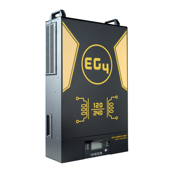
- Page 1 User Manual EG4 6000EX-48 INVERTER / CHARGER...
-
Page 2: Table Of Contents
Table Of Contents ABOUT THIS MANUAL ........................1 Purpose ............................... 1 Scope ..............................1 SAFETY INSTRUCTIONS ........................1 SPECIFICATIONS ..........................2 INTRODUCTION ..........................3 Product Overview ..........................4 INSTALLATION ..........................5 Unpacking and Inspection ........................5 Preparation ............................ -
Page 3: About This Manual
ABOUT THIS MANUAL Purpose This manual describes the assembly, installation, operation and troubleshooting of this unit. Please read this manual carefully before installation and operation. eep this manual for future reference. Scope This manual provides safety and installation guidelines as well as information on tools and wiring. SAFETY INSTRUCTIONS WARNING: This chapter contains important safety and operating instructions. -
Page 4: Specifications
SPECIFICATIONS MODEL RATED OUPUT POWER 6000W PV INPUT (DC) Max. PV Power 7500W Max. Input voltage 500 VDC (Maximum PV open voltage) DC Power MPPT range VDC~4 0 VDC Working MPP range 120 VDC~4 0 VDC Max. DC Input current / Number of MPP Tracker GRID-TIE OPERATION GRID OUTPUT (AC) -
Page 5: Introduction
INTRODUCTION This is a residential self-consumption multi-function inverter, combining the functions of an inverter, solar controller, and battery charger to offer uninterrupted power system in a single package. The comprehensive LCD display offers user-configurable and easily-accessible button operations such as battery charging current, AC or solar charging priority, and acceptable input voltage based on different applications. -
Page 6: Product Overview
Product Overview NOTE: For parallel installation and operation, refer to the commissioning guide and connection diagrams. LCD display Status indicator Charging indicator Fault indicator Function buttons Power on/off switch AC input connectors AC output connectors (Load connection) PV connections 10. Battery connections 11. -
Page 7: Installation
INSTALLATION Unpacking and Inspection Before installation, please inspect the unit. Be sure nothing inside the package is damaged. Check to ensure the Inverter unit Software CD Manual RS-232 Cable Battery Comms Cable Parallel Cable Preparation To prepare for the wiring step of installation, remove the bottom cover as shown below. Mounting the Unit Consider the following points before selecting a location for installation: Avoid mounting the inverter on combustible construction materials. -
Page 8: Battery Connection
Mounting the Inverter Install the unit using all three screw holes. Use #8 (M4) or #10 (M5) screws. Battery Connection CAUTION: For safe operation and regulation compliance, it s requ to install a separate DC over-current protector or disconnect device between battery and inverter. It may not be requ to have a disconnect device in some applications, however, to have over-current protection installed. -
Page 9: Ac Input/Output Connection
WARNING: Shock Hazard Installation must be performed ; arc and shock hazards are present. CAUTION! Do not place anything between the flat part of the inverter terminal and the ring terminal. Mixed materials, gaps, and loose connections can all lead to overheating. CAUTION! Do not apply anti-oxidant substance on the terminals before terminals are connected. -
Page 10: Pv Connection
WARNING: Ensure all AC power sources and loads are disconnected before wiring the unit. 4. Insert the AC output wires according to labeling on the terminal block and tighten terminal screws. Be sure to connect the grounding conductor ( ) first. Ground (Green or Green with a Yellow stripe) Line 1 (Black) Cord grips or other approved... -
Page 11: Final Assembly
CAUTION: It is required to use a PV surge protection device. Damage to the inverter can occur from surges such as lighting or short circuit . Model Typical Amperage Cable Size Torque 10AWG ~17-21 in-lbs (-2.0-2.4Nm) PV Module Selection: Open Circuit Voltage (Voc) of the PV modules/strings must not exceed the maximum rating. -
Page 12: Communication Connection
Communication Connection Serial Connection Please use supplied communication cable to connect to inverter and PC. Insert bundled CD into a computer and follow on-screen instruction to install the monitoring software. For the detailed software operation , please check user manual of software Wi-Fi Connection Wi-Fi module can enable wireless communication between off-grid inverters and... -
Page 13: Operation
OPERATION Power ON/OFF After completing installation of the unit, the next step is powering on for setup. Start by pressing the On/Off switch (located on display unit) to on the system. Operation and Display Panel Refer to the diagram and table below for details on the operation and display panel. There are three indicators, four function keys, and an LCD display. -
Page 14: Lcd Display Icons
Function Keys Function Key Description Exit the setting/go back Reserved Reserved Reserved Reserved Scroll to previous selection Down Scroll to next selection Enter To confirm/enter the selection in setting mode LCD Display Icons Icon Function Input source information Indicates AC input information is being displayed Indicates PV1 input information is being displayed Left digital display information Indicate input voltage, input frequency, battery voltage, PV... -
Page 15: Lcd Setting
Load information Indicates output overload. Indicates the load level by 0-24%, 25-49%, 50-74%, and 75-100%. 0%~24% 25%~49% 50%~74% 75%~100% Mode operation information Indicates connection to an AC input source. Indicates connection of the PV array. Indicates solar is being used to charge the battery bank. Indicates the DC/AC inversion is working. - Page 16 Appliances If selected, acceptable AC input (Default setting) voltage range will be set to 65-140VAC. AC input voltage range If selected, acceptable AC input voltage range will be set to 95-140VAC. 110Vac 120V (Default setting) Output voltage 50Hz 60Hz (Default setting) Output frequency Available power will Solar energy provides power to...
- Page 17 If this inverter/charger is working in Line, Standby or Fault mode, charger source can be programmed as below: Solar first Solar energy will charge battery as first priority. Utility/AC input will charge battery only when solar energy is not available. Solar and Utility Solar energy and utility/AC input will Charger source priority:...
- Page 18 LIb-protocol Select “ LIb” if using Lithium battery compatible to Lib protocol. If selected, programs of 11, 17, 18 and 19 will be automatically set up. No need for further setting. party Lithium If selected, programs of 11, 17, 18 battery and 19 will be automatically set up.
- Page 19 Return to default If selected, no matter how users display screen (default) switch display screen, it will automatically return to default display screen (Input voltage /output voltage) after no button is Auto return to default display screen pressed for 1 minute. Stay at latest screen If selected, the display screen will stay at latest screen user...
- Page 20 00:00 (default setting) Start charging time for AC charger The setting range of start time for AC charger is from 00:00 to 23:00, 00:00 (default setting) Stop charging time for AC charger The setting range of stop charging time for AC charger is from 00:00 to 23:00, 00:00 (default setting) Scheduled time for AC output...
-
Page 21: Display Setting
Display Setting The LCD display information is cycled through by pressing “UP” or “DOWN” keys. The selectable information is switched as below order: input voltage, input frequency, PV voltage, charging current, battery voltage, output voltage, output frequency, load percentage, load in watts, load in VA, load in watts, DC discharging current, main board firmware version and SCC firmware version. - Page 22 Input 2 frequency=60.0Hz, output 2 frequency=60.0Hz Input 2 frequency and output 2 frequency Battery Voltage=48.0V, output 1 voltage=120V Battery voltage and output 1 voltage Battery Voltage=48.0V, output 2 voltage=120V Battery voltage and output 2 voltage Battery Voltage=48.0V, load 1 percentage = 68% Battery voltage and load 1 percentage...
- Page 23 Battery Voltage=48.0V, load 2 percentage = 68% Battery voltage and load 2 percentage Battery Voltage=48.0V, load 1 in VA=1.08kVA Battery voltage and load 1 in VA Battery Voltage=48.0V, load 2 in VA=1.08kVA Battery voltage and load 2 in VA Battery Voltage=48.0V, load 1 in Watt=1.88kW Battery voltage and load 1 in watts...
- Page 24 Battery Voltage=48.0V, load 2 in Watt=1.88kW Battery voltage and load 2 in watts PV1 Voltage=360V, PV power=1.58kW PV1 voltage and PV power Charging current=30A, discharging current=0A Charger current and DC discharging current Daily production example = 6.3kWh PV energy generated today...
- Page 25 Monthly energy example = 358kWh PV energy generated this month Yearly energy example = 8.32MWh PV energy generated this year Total energy example = 13.9MWh Lifetime PV energy generated Date example Nov 28, 2016. Date...
-
Page 26: Operating Mode Description
Time example 13:20. Time Main CPU version 00001.00 Main CPU version checking. Secondary CPU version 00020.21 Secondary CPU version checking. Operating Mode Description Operating mode Behaviors LCD display The battery is charging using utility/AC input power. Standby mode Note: *Standby mode: The inverter is not turned on yet but at this time, the inverter can The battery is charging using PV energy. - Page 27 Battery is charged by PV energy and feed PV energy to grid. The battery is not charging. Utility charges battery and provides power to load. Output power from Line mode utility. Charger Utility and battery power provide power to load. available PV energy, battery power and utility provide power to load.
- Page 28 PV energy and the battery are supplying power to the loads. PV energy is charging the battery and providing power to the loads. Output power from Battery mode battery or PV The battery is providing power to the loads. PV energy is providing power to the loads. Only PV mode Output power from PV The battery is not charging.
-
Page 29: Parallel Function
Parallel Function 1. Introduction This inverter can be used in parallel in only split phase systems. A maximum of nine units can parallel together. The supported maximum output power is 54kW/54KVA. *If you want to use only one breaker at the battery side for the whole system, the rating of the breaker should be X times current of 1 unit. - Page 30 Three inverters in parallel: Power Connection Communication Connection Four inverters in parallel: Power Connection Communication Connection...
- Page 31 Five inverters in parallel: Power Connection Communication Connection Six inverters in parallel: Power Connection Communication Connection...
- Page 32 Seven inverters in parallel: Power Connection Communication Connection Eight inverters in parallel: Power Connection Communication Connection Nine inverters in parallel: Power Connection Communication Connection...
- Page 33 3. LCD Setting and Display Setting Program: Program Description Selectable option Single: When selected, the unit is used in single AC output mode operation. *This setting is only available when the Parallel: When selected, this inverter is operated in parallel system. The maximum inverter is in standby parallel unit is 9.
-
Page 34: Bms Communication Install
BMS Communication Install – EG4-LL 1. Introduction When connecting to an EG4-LL battery use the supplied RJ45 battery communication cable. Please check with your dealer or installer for details. This custom-made RJ45 communication cable delivers information and signal between lithium battery and the inverter. - Page 35 Battery Communication Install - EG4-LL Cont. Using the 1ft RS485 cable, interconnect the batteries as illustrated in the diagram below.
- Page 36 Battery Communication Install – LiFePower4 Using the 1ft RS485 cable, interconnect the batteries as illustrated in the diagram below.
- Page 37 Setting for 1). Dip Switch: There are 4 Dip Switches set different baud rate and battery group address . If switch position is turned to the “OFF” position, it means “0”. If switch position is turned to the “ON” position, it means “1”. Dip 1 “O ”...
-
Page 38: Battery Based Commissioning Guide
Battery Based Commissioning Note: Systems must be commissioned while connected to a battery bank. PV or AC input only based commissioning is not recommended or supported. NOTE: This guide is to be used after the physical installation of the system is complete. NOTE: For best use case, ensure that all settings are programmed per user/site specific requirements. - Page 39 Battery Based Commissioning Cont. Multi-unit Systems: Step 1 - Ensure all inverter connections are correct, and all breakers in/out of the unit are off. Step 2 - Provide power from the battery to the inverters, and power both inverters on. Step 3 - After the startup countdown, hold the enter “...
-
Page 40: Troubleshooting
Warning Indicator Warning Code Warning Event Icon flashing Fan locked Over temperature Battery over charged Low battery Overload Inverter power derating PV is weak Battery is not connected... - Page 41 Faults Reference Code Fault Code Fault Event Icon on Fan is locked. Over temperature Battery voltage is too high. Battery voltage is too low. Output is short circuited. Output voltage is abnormal. Overload time out. Bus voltage is too high. Bus soft start failure.
- Page 42 Problem LCD/LED/Buzzer Explanation / Possible cause What to do Unit shuts down LCD/LEDs and buzzer automatically will be active for 3 The battery voltage is too low 1. Re-charge battery. during startup seconds and then (<1.91V/Cell) 2. Replace battery. process. complete off.
- Page 43 Situation Solution Fault Fault Event Description Code Restart the inverter. Check if L /N cables are inverters. Current feedback into For parallel system in split phase, make sure the the inverter is detected. sharing cables are connected well to all inverters. If the problem remains, please contact your installer.
-
Page 44: Wi-Fi Operation Guide In Remote Panel
Wi-Fi Operation Guide in Remote Panel 1. Introduction Wi-Fi module can enable wireless communication between off-grid inverters and monitoring platform. Users have complete and remote monitoring and control experience for inverters when combining Wi-Fi module with SolarPower APP, available for both iOS and Android based device. All data loggers and parameters are saved in The major functions of this APP: Delivers device status during normal operation. - Page 45 Then, a “Registration success” window will pop up. Tap “Go now” to continue setting local Wi-Fi network connection. Step 2: Local Wi-Fi Module Configuration Now, you are in “Wi-Fi Config” page. There are detailed setup procedure listed in “How to connect?” section and you may follow it to connect Wi-Fi.
- Page 46 Then, return to SolarPower APP and tap “ ” button when Wi-Fi module is connected successfully. Step 3: Wi-Fi Network settings icon to select your local Wi-Fi router name (to access the internet) and enter password. Step 4: Tap “Confirm” to complete the Wi-Fi configuration between the Wi-Fi module and the Internet. If the connection fails, please repeat Step 2 and 3.
- Page 47 Diagnose Function If the module is not monitoring properly, please tap “ ” on the top right corner of the screen for further details. It will show repair suggestion . Please follow it to fix the problem. Then, repeat the steps in the chapter 4.2 to re-set network setting.
- Page 48 Overview After login is successful, you can access “Overview” page to have overview of your monitoring devices, including overall operation situation and nergy information for urrent power and power as below diagram. Devices Tap the icon (located on the bottom) to enter Device List page. You can review all devices here by adding or deleting Wi-Fi Module in this page.
- Page 49 Part number label is pasted on the bottom of remote LCD panel. For more information about Device List, please refer to the section 2.4. In ME page, users can modify “My information”, including User’s Photo , Account security , Modify password , Clear cache ,and Log-out , shown as below diagrams.
- Page 50 Device Mode On the top of screen, there is a dynamic power flow chart to show live operation. It contains five icons to present PV power, inverter, load, utility and battery. Based on your inverter model status, there will be Standby Mode , Line Mode , Battery Mode .
- Page 51 Swipe left Basic Information displays basic information of the inverter, including AC voltage, AC frequency, PV input voltage, Battery voltage, Battery capacity, Charging current, Output voltage, Output frequency, Output apparent power, Output active power and Load percent. Please slide up to see more basic information. Production Information displays Model type (Inverter type), Main CPU version and secondary CPU version.
-
Page 52: Parameter Setting List
Please refer to below parameter setting list for an overall description and that the available parameters may vary depending on different models. Please always see the original product manual for detailed setting instructions. Parameter setting list: Item Description Output setting Output source To configure load power source priority. - Page 53 Record happens. Solar Supply Set solar power as priority to charge the battery or to power the load. Priority Reset PV If clicked, PV energy storage data will be reset. Energy Storage Start Time For The setting range of start charging time for AC charger is from 00:00 to Enable AC 23:00.
Need help?
Do you have a question about the 6000EX-48 and is the answer not in the manual?
Questions and answers