
Related Manuals for EG4 6500 EX-48


Summary of Contents for EG4 6500 EX-48
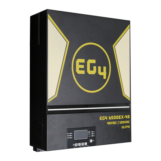
- Page 1 EG4 Electronics www.eg4electronics.com 6500 EX-48 6.5KVA 120Vac May 2022 | Rev A | Information subject to change without notice.
- Page 2 Battery Type - Determine the battery chemistry of the batteries being used and input that here Batteries= EG4, for all other batteries use User Defined Settings. • Program Setting 6 Overload restart option - If enabled, the unit will restart itself when the load requested exceeds 120% of inverter capacity.
- Page 3 EG4 Electronics www.eg4electronics.com • Program Setting 12 Low Battery Voltage Level - Determine the lowest point you would like to discharge your batteries to before passing the load / charging responsibility to the AC input. Input that here. Most will use 48.0V •...
- Page 4 • Program Setting 30-36 Battery Equalization settings When using EG4 you will not need these settings. If using flooded lead acid or AGM batteries consult your batteries user manual for recommended Equalization settings. rogram Setting 37 • Rest all stored data for PV generated power and output load energy Program Setting 41 •...
-
Page 5: Table Of Contents
EG4 Electronics www.eg4electronics.com Table of Contents ABOUT THIS MANUAL ..........................1 Purpose ................................. 1 Scope ................................1 SAFETY INSTRUCTIONS .........................1 INTRODUCTION ............................ 2 Features................................ 2 Basic System Architecture..........................2 Product Overview ............................3 INSTALLATION ............................4 Unpacking and Inspection ..........................4 Installation of Battery Wiring Extension Box and Cable Glands ................4... -
Page 6: About This Manual
EG4 Electronics www.eg4electronics.com ABOUT THIS MANUAL Purpose This manual describes the assembly, installation, operation and troubleshooting of this unit. Please read this manual carefully before installations and operations. Keep this manual for future reference. Scope This manual provides safety and installation guidelines as well as information on tools and wiring. -
Page 7: Introduction
EG4 Electronics www.eg4electronics.com INTRODUCTION This is a residential self consumption multi-function inverter, combining the functions of an inverter, solar charger and battery charger to offer uninterrupted power support in a single package. The comprehensive LCD display offers user-configurable and easy-accessible button operations such as battery charging current, AC or solar charging priority, and acceptable input voltage based on different applications. -
Page 8: Product Overview
EG4 Electronics www.eg4electronics.com Product Overview Appendix I. NOTE: 6.5KW is a parallel model. For parallel installation and operation, please check LCD display 12. Current sharing port Status indicator 13. Parallel communication port Charging indicator 14. Dry contact Fault indicator 15. OTG-USB port as USB communication port and USB... -
Page 9: Installation
EG4 Electronics www.eg4electronics.com INSTALLATION: Unpacking and Inspection Before installation, please inspect the unit. Be sure that nothing inside the package is damaged. You should have received the following items: Inverter unit Manual software CD RS-232 cable Parallel communication cable Current sharing cable... -
Page 10: Preparation
EG4 Electronics www.eg4electronics.com Preparation Before connecting all wirings, please take off bottom cover by removing five screws. When removing the bottom cover, be carefully to remove three cables as shown below. Mounting the Unit Consider the following points before selecting where to install: Do not mount the inverter on flammable construction materials. -
Page 11: Battery Connection
EG4 Electronics www.eg4electronics.com Battery Connection CAUTION: For safety operation and regulation compliance, it is recommended that a separate DC over- current protector or disconnect device be installed between the battery and inverter. It may not be required to have a disconnect device in some applications, however, it is still recommended to have over-current protection installed. -
Page 12: Ac Input/Output Connection
EG4 Electronics www.eg4electronics.com AC Input/Output Connection CAUTION!! Before connecting to AC input power source, please install a separate AC breaker between the inverter and AC input power source. This will ensure the inverter can be securely disconnected during maintenance and fully protected from over current of AC input. -
Page 13: Pv Connection
EG4 Electronics www.eg4electronics.com 5. Then, insert AC output wires according to polarities indicated on terminal block and tighten terminal screws. Be sure to connect PE protective conductor ( ) first. →Ground (yellow-green) L→LINE (brown or black) N→Neutral (blue) 6. Make sure the wires are securely connected. - Page 14 EG4 Electronics www.eg4electronics.com Step 3: Assemble PV terminals with PV modules by the following steps. Please follow below steps to implement PV module connection: 1. Remove insulation sleeve 10 mm for positive and negative conductors. 2. Check correct polarity of connection cable from PV modules and PV input connectors.
-
Page 15: Final Assembly
EG4 Electronics www.eg4electronics.com Final Assembly After correctly connecting all wiring, re-connect three cables and then put bottom cover back by screwing five screws as shown below. Remote Display Panel Installation The LCD module can be removed and installed in a remote location with an optional communication cable. - Page 16 EG4 Electronics www.eg4electronics.com Step 2. Prepare your mounting holes in the marked locations as shown in the illustration below. The LCD module then can be securely mounted to your desired location. Note: Wall installation should be implemented with the proper screws to the right.
-
Page 17: Communication Connection
EG4 Electronics www.eg4electronics.com Communication Connection Serial Connection Please use the supplied serial cable for connection between the inverter and your PC. Install the monitoring software from the bundled CD and follow the on-screen instructions to complete your installation. For detailed software operation, refer to the software user manual on the bundled CD. -
Page 18: Operation
EG4 Electronics www.eg4electronics.com OPERATION Power ON/OFF Once the unit has been properly installed and the batteries are connected correctly, simply press the On/ Off switch (located on the display panel) to turn on the unit. Inverter Start-Up After this inverter is turned on, the WELCOME light show will be started with RGB LED BAR. It will slowly cycle through entire spectrum of nine colors (Green, Sky blue, Royal blue, Violet, Pink, Red, Honey, Yellow, Lime yellow) for about 10-15 seconds. -
Page 19: Lcd Display Icons
EG4 Electronics www.eg4electronics.com Function Keys Function Key Description Exit the setting USB function setting Select USB OTG functions Timer setting for the Output source Setup the timer for prioritizing the output source priority Timer setting for the Charger source Setup the timer for prioritizing the charger source... - Page 20 EG4 Electronics www.eg4electronics.com Status Battery voltage LCD Display <2V/cell 4 bars will flash in turns. Bottom bar will be on and the other three bars Constant 2 ~ 2.083V/cell will flash in turns. Current mode / Bottom two bars will be on and the other two 2.083 ~ 2.167V/cell...
-
Page 21: Lcd Setting
EG4 Electronics www.eg4electronics.com LCD Setting General Setting ” button for 3 seconds, the unit will enter the Settings Menu. After pressing and holding “ button to select setting programs. Press “ ” or “ ” Press “ ” button to confirm you selection or “... - Page 22 If “User-Defined” is selected, battery charge voltage and low DC cut-off voltage can be set up in program 26, 27 and 29. If using EG4 batteries you will use this battery type for BMS communications. If this Battery type battery type is selected settings 2,26, 27 will be configured by the BMS.
- Page 23 EG4 Electronics www.eg4electronics.com Restart disable (default) Restart enable Auto restart when overload occurs Restart disable (default) Restart enable Auto restart when over temperature occurs 50Hz 60Hz (default) Output frequency 110V 120V (default) Output voltage 127V...
- Page 24 EG4 Electronics www.eg4electronics.com Maximum utility charging 30A (default) current Setting range is 2A, then from 10A Note: If setting value in program 02 is smaller than to 120A. Increment of each click is that in program in 11, the 10A.
- Page 25 EG4 Electronics www.eg4electronics.com Solar and Utility (default) Solar energy and utility will charge battery at the same time. Only Solar Charger source priority: To configure charger source Solar energy will be the only priority charger source no matter utility is available or not.
- Page 26 EG4 Electronics www.eg4electronics.com Alarm on (default) Alarm off Beeps while primary source is interrupted Bypass disable (default) Bypass enable Overload bypass: When enabled, the unit will transfer to line mode if overload occurs in battery mode. Record enable (default) Record disable Record Fault code default: 56.4V...
- Page 27 EG4 Electronics www.eg4electronics.com L1 phase: L2 phase: L3 phase: AC output mode L1 for split phase: L2 for split phase: *This setting only available when the inverter (120° phase difference) is in standby mode (Switch off). L2 for split phase: (180°...
- Page 28 EG4 Electronics www.eg4electronics.com If “Flooded” or “User-Defined” is selected in program 05, this program can be set up. default: 58.4V Setting range is from 48.0V to 62.0V. Increment of each click is Battery equalization voltage 0.1V. 60min (default) Setting range is from 5min to 900min.
- Page 29 EG4 Electronics www.eg4electronics.com Disable (Default) If selected, battery discharge protection is disabled. Maximum discharging The setting range is from 30 A to current 150 A. Increment of each click is 10A. If discharging current is higher than setting value, battery will stop discharging.
- Page 30 EG4 Electronics www.eg4electronics.com High Scrolling Breathing RGB LED effects Solid on (Default) C01: (Default) C02: Color combination of RGB Violet-White-Sky blue White-Yellow-Green ⚫ ⚫ LED to show energy source Pink-Honey Royal blue-Lime yellow ⚫ ⚫ and battery charge/discharge status: ⚫ Grid-PV-Battery ⚫...
- Page 31 EG4 Electronics www.eg4electronics.com 30 minutes 60 minutes Data log recorded interval *The maximum data log number is 1440. If it’s over 1440, it will re-write the first log. For minute setting, the range is from 0 to 59. Time setting – Minute For hour setting, the range is from 0 to 23.
- Page 32 EG4 Electronics www.eg4electronics.com Function Setting There are three function keys on the display panel to implement special functions such as USB OTG, Timer setting for output source priority and timer setting for charger source priority. 1. USB Function Setting Insert an OTG USB disk into the USB port ( ).
- Page 33 EG4 Electronics www.eg4electronics.com 2. Timer Setting for Output Source Priority This timer setting is to set up the output source priority per day. Procedure LCD Screen Step 1: Press and hold “ ” button for 3 seconds to enter Timer Setup Mode for output source priority.
- Page 34 EG4 Electronics www.eg4electronics.com Press “ ” button to set up Solar & Utility Timer. Press “ ” button to select staring time. Press “ ” or “ ” button to adjust values and press “ ” to confirm. Press “...
-
Page 35: Lcd Display
EG4 Electronics www.eg4electronics.com LCD Display The LCD display information table will be switched in turn by pressing the “UP” or “DOWN” button. The selectable information is switched as the following table in order. Selectable information LCD display Input Voltage=120V, output voltage=120V... - Page 36 EG4 Electronics www.eg4electronics.com PV1 power = 500W PV power PV2 power = 500W AC and PV charging current=50A PV charging current=50A Charging current AC charging current=50A...
- Page 37 EG4 Electronics www.eg4electronics.com AC and PV charging power=500W PV charging power=500W Charging power AC charging power=500W Battery voltage=55.5V, output voltage=120V Battery voltage and output voltage Output frequency=60Hz Output frequency Load percent=70% Load percentage...
- Page 38 EG4 Electronics www.eg4electronics.com When connected load is lower than 1kVA, load in VA will present xxxVA like below chart. Load in VA When load is larger than 1kVA (≧1KVA), load in VA will present x.xkVA like below chart. When load is lower than 1kW, load in W will present xxxW like below chart.
- Page 39 EG4 Electronics www.eg4electronics.com This PV month energy = 388kWh, Load month energy= 950kWh. PV energy generated this month and Load output energy this month. This PV year energy = 3.88MWh, Load year energy = 9.50MWh. PV energy generated this year and Load output energy this year.
-
Page 40: Operating Mode Description
EG4 Electronics www.eg4electronics.com Secondary CPU version 00012.03. Secondary CPU version checking. Wi-Fi version 00000.24. Wi-Fi version checking. Operating Mode Description Operation mode Description LCD display Charging by utility and PV energy. Charging by utility. Standby mode No output is supplied by the... - Page 41 EG4 Electronics www.eg4electronics.com Operation mode Description LCD display Fault mode Note: No charging. No charging at all no matter *Fault mode: Errors are if grid or PV power is caused by inside circuit error or external reasons such as available.
- Page 42 EG4 Electronics www.eg4electronics.com Operation mode Description LCD display Power from battery and PV energy. PV energy will supply power to the loads and charge battery at the same time. No utility is available. The unit will provide output Battery Mode power from battery and/or PV power.
-
Page 43: Faults Reference Code
EG4 Electronics www.eg4electronics.com Faults Reference Code Fault Code Fault Event Icon on Fan is locked when inverter is off. Over temperature Battery voltage is too high Battery voltage is too low Output short circuited. Output voltage is too high. Overload time out... -
Page 44: Warning Indicator
EG4 Electronics www.eg4electronics.com Warning Indicator Warning Warning Event Audible Alarm Icon flashing Code Beep three times every Fan is locked when inverter is on. second Over temperature None Battery is over-charged Beep once every second Low battery Beep once every second Overload Beep once every 0.5 second... -
Page 45: Battery Equalization
EG4 Electronics www.eg4electronics.com BATTERY EQUALIZATION The equalization function is added into charge controller. It reverses the buildup of negative chemical effects like stratification, a condition where acid concentration is greater at the bottom of the battery than at the top. Equalization also helps to remove sulfate crystals that might have built up on the plates. If left unchecked, this condition, called sulfation, will reduce the overall capacity of the battery. -
Page 46: Clearance And Maintenance For Anti-Dust Kit
EG4 Electronics www.eg4electronics.com CLEANING AND MAINTENANCE FOR ANTI-DUST KIT Overview Every inverter is already installed with anti-dusk kit from the factory. The inverter will automatically detect this kit and activate internal thermal sensor to adjust internal temperature. This kit also keeps dust out of your inverter and increase the product reliability in harsh environments. -
Page 47: Specifications
EG4 Electronics www.eg4electronics.com SPECIFICATIONS Table 1 Line Mode Specifications MODEL 6.5KW Input Voltage Waveform Sinusoidal (utility or generator) Nominal Input Voltage 120Vac 90Vac±7V (UPS) Low Loss Voltage 80Vac±7V (Appliances) 100Vac±7V (UPS); Low Loss Return Voltage 90Vac±7V (Appliances) High Loss Voltage 140Vac±7V... - Page 48 EG4 Electronics www.eg4electronics.com Table 2 Inverter Mode Specifications MODEL 6.5KW 6,500W Rated Output Power Output Voltage Waveform Pure Sine Wave >3% THD Output Voltage Regulation 120Vac±5% 60Hz or 50Hz Output Frequency Peak Efficiency 100ms@≥205% load;5s@≥150% load; 10s@110%~150% load Overload Protection...
- Page 49 EG4 Electronics www.eg4electronics.com Table 3 Charge Mode Specifications Utility Charging Mode MODEL 6.5KW Charging Current (UPS) 120A @ Nominal Input Voltage Flooded 58.4Vdc Battery Bulk Charging Voltage AGM / Gel 56.4Vdc Battery Floating Charging Voltage 54.0Vdc 66.0Vdc Overcharge Protection Charging Algorithm...
- Page 50 EG4 Electronics www.eg4electronics.com Table 4 General Specifications MODEL 6.5KW Safety Certification UL 1741 Certificate by TUV -10°C to 40°C Operating Temperature Range -15°C~ 60°C Storage temperature Humidity 5% to 95% Relative Humidity (Non-condensing) Dimension 58.03in x 170.2in x 226.6in (244.3in) (with extension box)
-
Page 51: Trouble Shooting
EG4 Electronics www.eg4electronics.com TROUBLE SHOOTING Problem LCD/LED/Buzzer Explanation / Possible cause What to do Unit shuts down LCD/LEDs and buzzer automatically will be active for 3 The battery voltage is too low 1. Re-charge battery. during startup seconds and then (<1.91V/Cell) -
Page 52: Appendix I: Parallel Function
EG4 Electronics www.eg4electronics.com Appendix I: Parallel Function 1. Introduction This inverter can be used in parallel with three different operation modes. 1. Parallel operation in single phase is with up to 6 units. The supported maximum output power is 39KW/39KVA. - Page 53 EG4 Electronics www.eg4electronics.com Recommended battery capacity Inverter parallel numbers Battery Capacity 200AH 300AH 400AH 600AH 600AH WARNING! Be sure that all inverters will share the same battery bank. Otherwise, the inverters will transfer to fault mode. 4-1. Parallel Operation in Single phase...
- Page 54 EG4 Electronics www.eg4electronics.com Three inverters in parallel: Power Connection Communication Connection Four inverters in parallel: Power Connection Communication Connection...
- Page 55 EG4 Electronics www.eg4electronics.com Five inverters in parallel: Power Connection Communication Connection Six inverters in parallel: Power Connection Communication Connection...
- Page 56 EG4 Electronics www.eg4electronics.com 4-2. Support 3-phase equipment Two inverters in each phase: Power Connection Communication Connection Four inverters in one phase and one inverter for the other two phases: Power Connection Communication Connection...
- Page 57 EG4 Electronics www.eg4electronics.com Three inverters in one phase, two inverters in second phase and one inverter for the third phase: Power Connection Communication Connection Three inverters in one phase and only one inverter for the remaining two phases: Power Connection...
- Page 58 EG4 Electronics www.eg4electronics.com Two inverters in two phases and only one inverter for the remaining phase: Power Connection Communication Connection Two inverters in one phase and only one inverter for the remaining phases: Power Connection Communication Connection...
- Page 59 EG4 Electronics www.eg4electronics.com One inverter in each phase: Power Connection Communication Connection WARNING: Do not connect the current sharing cable between inverters which are in different phases. Otherwise, it may damage the inverters. 4-3. Support split-phase equipment Three inverters in each phase:...
- Page 60 EG4 Electronics www.eg4electronics.com Two inverters in each phase: Power Connection Communication Connection One inverter in each phase: Power Connection Communication Connection 5. PV Connection Please refer to user manual of single unit for PV Connection. CAUTION: Each inverter should connect to PV modules separately.
- Page 61 EG4 Electronics www.eg4electronics.com 6. LCD Setting and Display Setting Program: Program Description Selectable option Single When the unit is operated alone, please select “SIG” in program 28. AC output mode When the units are used in parallel for Parallel *This setting is able...
- Page 62 EG4 Electronics www.eg4electronics.com Fault code display: Fault Code Fault Event Icon on Power feedback protection Firmware version inconsistent Current sharing fault CAN fault Host loss Synchronization loss Battery voltage detected different AC input voltage and frequency detected different AC output current unbalance...
- Page 63 EG4 Electronics www.eg4electronics.com Step 4: Switch on all AC Input breakers . It’s better to have all inverters connect to utility at the same time. If not, it will display fault 82 in following-order inverters. However, these inverters will automatically restart. If the units detect AC connection, they will work normally.
- Page 64 EG4 Electronics www.eg4electronics.com 8. Trouble shooting Situation Fault Solution Fault Event Description Code Restart the inverter. Check if L/N cables are not connected reversely in all inverters. For parallel system in single phase, make sure the sharing are Current feedback into connected in all inverters.
-
Page 65: Appendix Ii: Bms Communication Installation
EG4 Electronics www.eg4electronics.com Appendix II: BMS Communication Installation- EG4-LL 1. Introduction When connecting to lithium battery, it is recommended to purchase a custom-made RJ45 communication cable. Please check with your dealer or integrator for details. This custom-made RJ45 communication cable delivers information and signal between lithium battery and the inverter. - Page 66 EG4 Electronics www.eg4electronics.com Battery Networking- EG4-LL Using the 1ft RS485 cable interconnect your batteries as illustrated in the diagram below.
- Page 67 EG4 Electronics www.eg4electronics.com Battery Networking-LiFePower4 Using the 1ft RS485 cable interconnect your batteries as illustrated in the diagram below.
- Page 68 NOTE: For EG4-LL Ensure to turn on the red power switch as well as the breaker. NOTE: Despite EG4 batteries having built-in breakers. It is still recommended to have a 125A in line breaker. NOTE: The 1st (top battery) must have the master address as defined above. Every battery below that must...
- Page 69 EG4 Electronics www.eg4electronics.com 6. Code Reference Related information code will be displayed on LCD screen. Please check inverter LCD screen for the operation. Code Description Action If battery status is not allowed to charge and discharge after the communication between...
-
Page 70: Appendix Iii: The Wi-Fi Operation Guide In Remote Panel
EG4 Electronics www.eg4electronics.com Appendix III: The Wi-Fi Operation Guide in Remote Panel 1. Introduction Wi-Fi module can enable wireless communication between off-grid inverters and monitoring platform. Users have complete and remote monitoring and controlling experience for inverters when combining Wi-Fi module with WatchPower APP, available for both iOS and Android based device. - Page 71 EG4 Electronics www.eg4electronics.com Then, a “Registration success” window will pop up. Tap “Go now” to continue setting local Wi-Fi network connection. Step 2: Local Wi-Fi Module Configuration Now, you are in “Wi-Fi Config” page. There are detailed setup procedure listed in “How to connect?” section and you may follow it to connect Wi-Fi.
- Page 72 EG4 Electronics www.eg4electronics.com Step 3: Wi-Fi Network settings icon to select your local Wi-Fi router name (to access the internet) and enter password. Step 4: Tap “Confirm” to complete the Wi-Fi configuration between the Wi-Fi module and the Internet. If the connection fails, please repeat Step 2 and 3.
- Page 73 EG4 Electronics www.eg4electronics.com 2-3. Login and APP Main Function After finishing the registration and local Wi-Fi configuration, enter registered name and password to login. Note: Tick “Remember Me” for your login convenience afterwards. Overview After login is successfully, you can access “Overview” page to have overview of your monitoring devices, including overall operation situation and Energy information for Current power and Today power as below diagram.
- Page 74 EG4 Electronics www.eg4electronics.com Devices Tap the icon (located on the bottom) to enter Device List page. You can review all devices here by adding or deleting Wi-Fi Modules in this page. Add device Delete device Tap the icon on the top right corner and manually enter part number to add device. This part number label is pasted on the bottom of remote LCD panel.
- Page 75 EG4 Electronics www.eg4electronics.com 2-4. Device List In the Device List page, you can pull down to refresh the device information and then tap any device you want to check up for its real-time status and related information as well as to change parameter settings.
- Page 76 EG4 Electronics www.eg4electronics.com 【Battery Mode】 Inverter will power the load from the batter with or without PV charging. Only PV source can charge battery. Device Alarm and Name Modification In this page, tap the icon on the top right corner to enter the device alarm page. Then, you can review alarm history and detailed information.
- Page 77 EG4 Electronics www.eg4electronics.com 【Rated Information】displays information of Nominal AC voltage, Nominal AC current, Rated battery voltage, Nominal output voltage, Nominal output frequency, Nominal output current, Nominal output apparent power and Nominal output active power. Please slide up to see more rated information.
- Page 78 EG4 Electronics www.eg4electronics.com Charger source To configure charger source priority. priority: Max. charging current It’s to set up battery charging parameters. The selectable values in Max. AC charging different inverter model may vary. current: Please see product manual for the details.
-
Page 79: Appendix Iiii: Ul Listing
EG4 Electronics www.eg4electronics.com... - Page 80 EG4 Electronics www.eg4electronics.com 2022.04.26 09:01:52 +08'00'...
Need help?
Do you have a question about the 6500 EX-48 and is the answer not in the manual?
Questions and answers