
Related Manuals for Leviton EV48S-DP


Summary of Contents for Leviton EV48S-DP
- Page 1 Electric Vehicle Charging Station Installation Manual Cat. No. EV48S-DP PK-A3525-10-00-5A...
-
Page 3: Table Of Contents
TABLE OF CONTENTS 1 Warnings and Cautions ........................4 Safety Standards and Specifications ..................5 3 Tools Needed ..........................6 Basic Interface ..........................8 Dimensions ............................9 Status Light Indicators ........................ 10 Installation ............................ 11 7.1 Wall Mount Installation ......................11 7.2 Electrical Connection ......................13 Error and Warning Messages ..................... -
Page 4: Warnings And Cautions
1 WARNINGS AND CAUTIONS WARNINGS: • TO AVOID FIRE, SHOCK, OR DEATH; TURN OFF POWER AT CIRCUIT BREAKER OR FUSE AND TEST THAT POWER IS OFF BEFORE WIRING, REPLACING OR SERVICING THE PRODUCT! • HAZARD OF ELECTROCUTION, SHOCK, EXPLOSION, OR ARC FLASH. This device has arcing or sparking parts that should not be exposed to flammable vapors. -
Page 5: Safety Standards And Specifications
UL840 (Clearance and Creepage) Energy Star Certified FCC Part 15 Certified California Type Evaluation Program (CTEP) Certified ISO 15118-2,3 Compliant Specifications Model Name EV48S-DP Rated Input Voltage 208-240 VAC / Single Phase Rated Output Current 48A x 2 AC Power Frequency 50/60 Hz... -
Page 6: Tools Needed
3 TOOLS NEEDED Tools Required: 1. Level 2. Drill 3. Rubber mallet 4. Philips screwdriver 5. Wire stripper 6. Voltmeter or digital multi-meter 7. 10 mm combination wrench 8. Flat blade screwdriver... - Page 7 3 TOOLS NEEDED Contents Include: Product Name Quantity AC Charger (With Charging Cable) User Manual Mounting Bracket Mounting Template M6 Expansion Screws T20 Torx Key Shorting Terminal Set Ring Terminal Cable Clamp AD 21.2 mm Conduit Fitting AD 42.5 mm Conduit Fitting Cable Gland Self-Tapping Screws 3.5*16 Manual...
-
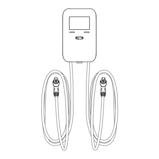
Page 8: Basic Interface
4 BASIC INTERFACE LCD screen Card swipe area AC power cord entry... -
Page 9: Dimensions
5 DIMENSIONS 12.2 in. 4.8 in. Mounting Bracket 30.98 cm 12.19 cm 2.8 in. 7.11 cm 19.2 in. 48.76 cm 4.8 in. 12.19 cm... -
Page 10: Status Light Indicators
6 Status Light Indicators Charger Indication Light Status Blue, Green, Power On - Blue, Green, and Red run clockwise Red Light Blue Light Standby - Solid Blue Green Light Charger Connected to Vehicle - Solid Green Waiting for Authentication (Swipe Card) - Green Blinking Green Light Blinking... -
Page 11: Installation
7 INSTALLATION Wall Mount Installation These instructions and included hardware are for mounting to a concrete wall. For other surfaces, obtain the appropriate mounting hardware. 1. Attach the Mounting Template • Position the template on the wall where the charger will be installed. •... - Page 12 7 INSTALLATION 5. Align the bracket’s screw holes with the holes in the wall. Insert the four expansion screws and use a rubber mallet to tap them in fully. 6. Tighten the screws with a combination wrench and attach the bracket to the wall. 7.
-
Page 13: Electrical Connection
7 INSTALLATION Electrical Connection 1. Remove the charger cover. Use the Torx key to unscrew the two screws securing the cover to the bottom of the enclosure. 2. Gently grasp the sides of the cover and pull it away to disengage the latches, then remove it. - Page 14 7 INSTALLATION Route and Connect Cables for Single Circuit Supplying Both Ports 1. Use shorting terminals to connect the L1 to L1 (1) and L2 to L2 (1). 2. Connect phase conductors to terminals marked L1 and L2, and the ground conductor to the terminal marked GND.
- Page 15 7 INSTALLATION Route and Connect Cables for Individual Circuits Supplying Each Port 1. Connect phase conductors from circuit 1 to terminals marked L1 and L2. 2. Connect phase conductors from circuit 2 to terminals marked L1 (1) and L2 (2). 3.
-
Page 16: Error And Warning Messages
8 ERRORS AND WARNING MESSAGES Fault Status Red Light Remark 1 flash followed by Meter Fault Auto Recover 3 second pause 2 flashes followed CP Fault Unplug the Connector to Recover by 3 second pause 3 flashes followed Auto Recover by 3 second pause 4 flashes followed Auto Recover... -
Page 17: Maintenance
9 MAINTENANCE WARNING: Avoid moisture or water in the charger. If there is water or moisture, immediately power OFF the charger, and notify professional personnel to perform maintenance before its next use. CAUTIONS: • Keep the charger clean and in an area with low humidity. Do not install it in an environment that is near the sea, or with high-oil, high-humidity, or high-dust. -
Page 18: Standard Statements And Warranty
Pointe-Claire (Quebec), Canada H9R 1E9 or by telephone at 1 800 405-5320. LIMITED 3 YEAR WARRANTY For Leviton’s limited 3 year product warranty, go to www.leviton.com. For a printed copy of the warranty, call 1-800-323-8920. For Technical Assistance Call: 1-800-824-3005 (USA Only) or 1-800-405-5320 (Canada Only) www.leviton.com...
Need help?
Do you have a question about the EV48S-DP and is the answer not in the manual?
Questions and answers