
Related Manuals for Leviton ChargePoint evr-green 4000


Summary of Contents for Leviton ChargePoint evr-green 4000
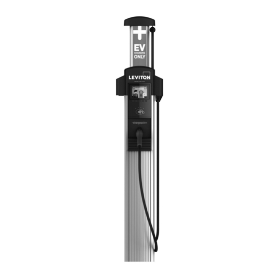
- Page 1 evr-green ® evr-green 4000 Networked Charging Station Cat. No. CPHU1, CPHU2, CPCMK, CPMEX, CPCAP-B, CPCAP-W, CPCBX, CPMBX Installation and Operation Manual PK-A3327-10-00-0A...
- Page 2 Charging Station on a concrete pad using a ® Leviton ChargePoint approved method. Failure to install on a surface that can support the full weight of the Charging Station can result in death, personal injury, or property damage. Inspect the Charging Station for proper installation before use.
- Page 3 evr-green ® PRODUCT USAGE INFORMATION Product Disposal Do not dispose of as part of unsorted domestic waste. Inquire with local authorities regarding proper disposal. Product materials are recyclable as marked. No Accuracy Guarantee Commercially reasonable efforts were made to ensure that the specifications and other information in this manual are accurate and complete at the time of its publication.
-
Page 4: Table Of Contents
6 Complete Station Setup .......................27 Power Up ............................27 Install Cable Clamps ........................27 Run the Installation Wizard ......................28 Secure the Head Assembly ......................28 Pinpoint the Station .........................29 Start a Charging Session ........................30 Activating a Leviton Charger ......................30 7 Warranty and Contact Information ....................31... -
Page 5: Introduction
® INTRODUCTION Leviton provides the all-purpose evr-Green 4000 Level 2 charging station for property owners, businesses, and municipalities. The evr-Green 4000 can be mounted on a pedestal or a wall. The evr-Green 4000 must be installed and serviced by ChargePoint approved Important: installers only. -
Page 6: Install A Pedestal Mount Evr-Green 4000
evr-green ® INSTALL A PEDESTAL MOUNT EVR-GREEN 4000 Gather Required Tools You need: • Ratchet and 10 mm (3/8 in) deep socket • 27 mm (1-1/16 in) socket wrench • Adjustable wrench • Level • #2 Phillips screwdriver • #3 Wire cutter •... - Page 7 INSTALL A PEDESTAL MOUNT EVR-GREEN 4000 Cat. No. CPCBX The station’s CPCBX box contains: • Cable Management Kit (CPCBX) • Pre-installed EV Charging Only sign • Cable clamps (2) The cable clamps are extra and will not be used Note: during installation.
-
Page 8: Prepare The Pedestal For Mounting
INSTALL A PEDESTAL MOUNT EVR-GREEN 4000 Prepare the Pedestal for Mounting Cat. No. CPMBX Using a 10 mm (3/8 in) socket wrench, loosen (but do not remove) the two screws holding the pedestal inside the housing. Remove and discard the cardboard shipping spacer. -
Page 9: Mount The Pedestal
INSTALL A PEDESTAL MOUNT EVR-GREEN 4000 Mount the Pedestal Pull wires through the conduit. Place the pedestal over the conduit, ensuring the curved front edge of the pedestal base is located where you want the front of the charging station. If the conduit is not coming up through the Note: center of the pedestal, install the conduit in the... -
Page 10: Install The Housing
INSTALL A PEDESTAL MOUNT EVR-GREEN 4000 Install the Housing Do not seal the pedestal to the concrete pad with caulking, silicone, Important: or other sealing material. Doing so traps water inside the housing. The pedestal is designed to shed moisture between its bottom surface and the concrete pad. -
Page 11: Prepare The Cpcmk For Mounting
INSTALL A PEDESTAL MOUNT EVR-GREEN 4000 When complete, the housing appears as shown. Prepare the CPCBX for Mounting Position the Cable Management Kit (CPCBX) packaging so that the bottom of the CPCBX is near the base of the pedestal. Do not unwrap the ropes. Note: Remove and discard the two shipping screws. -
Page 12: Install The Cpcmk
INSTALL A PEDESTAL MOUNT EVR-GREEN 4000 Install the CPCBX Insert the black cap into the space at the top of the housing, between the housing and the CPCBX. With a #3 Phillips screwdriver and at least one of the four screws (provided) in hand, slowly lift the CPCBX into position against the back of the housing. -
Page 13: Install A Wall Mount Evr-Green 4000
evr-green ® INSTALL A WALL MOUNT EVR-GREEN 4000 Gather Required Tools You need: • Ratchet and 15 mm (9/16 in) deep socket • #2 and #3 Phillips screwdrivers • Flathead screwdriver • Tape measure • Level • Marker • Wire stripper •... - Page 14 INSTALL A WALL MOUNT EVR-GREEN 4000 CPCBX The CPCBX box contains: • Cable Management Kit (CPCBX) pre-installed with EV Charging Only sign • Cable clamps (2) Top Cap The station’s top cap box contains: • Top cap • Installation Guide If installing both pedestal and wall-mount stations, also pay attention to the top Cat No.
-
Page 15: Drill Holes In The Wall
INSTALL A WALL MOUNT EVR-GREEN 4000 Drill Holes in the Wall Tear the packing box along the perforation to allow it to lay flat. Place the template against the wall. As described on the package insert, align the top where indicated, 1245 mm (49 in) above the floor or ground. -
Page 16: Prepare The Cpcbk For Mounting
INSTALL A WALL MOUNT EVR-GREEN 4000 Prepare the CPCBX for Mounting Position the Cable Management Kit (CPCBX) packaging so that the bottom of the CPCBX is near the wall. Note: Do not unwrap the ropes. Remove and discard the two shipping screws. When you remove the shipping Caution: screws, the counterweights are free to move... -
Page 17: Install The Housing
INSTALL A WALL MOUNT EVR-GREEN 4000 Install the Housing Push the tab on the terminal block cover to slide the cover up and expose the pre-drilled hole below the terminal block. Slide the cover upward until it stays in position. Remove the pre-installed flange bolts from the front brackets using a 10 mm (3/8 in) socket. -
Page 18: Install The Conduit
INSTALL A WALL MOUNT EVR-GREEN 4000 Install the Conduit Use a flathead screwdriver to remove the knockout for the appropriate conduit size, 25 mm or 20 mm (1 in or 3/4 in). Install and seal the conduit following local codes. When complete, proceed to Chapter 4 to connect the wiring to the station. -
Page 19: Connect Wiring
evr-green ® CONNECT WIRING WARNING: TO AVOID FIRE, SHOCK OR DEATH, turn off power at circuit breaker or fuse and test that the power is off before wiring. Use copper conductors only. Do not provide GFCI protection at the panel. The evr-green 4000 has built-in GFCI protection. -
Page 20: Review Wiring Diagrams
CONNECT WIRING Review Wiring Diagrams The wiring diagrams below show wiring for installing a dual port Evr-Green 4000 on a dual circuit. Two dedicated circuits are required, each with its own two-pole 40 A breaker, unless it is configured for operating at reduced power. 208 VAC, THREE PHASE PANEL... - Page 21 CONNECT WIRING 240 VAC, SINGLE PHASE PANEL...
-
Page 22: Wiring For Dual Or Single Port Stations
CONNECT WIRING Wiring for Dual (CPHU2) or Single (CPHU1) Port Stations Strip wires 13 mm (1/2 in). Push the black tab on the terminal block to release the terminal block cover. Slide the cover up until it locks into the raised position. - Page 23 CONNECT WIRING Dual Port Wiring Cat. No. CPHU2 Insert the 240 VAC L1 and L2 wires. Push the levers down until they click into their fully closed position. As shipped, a evr-green 4000 charging Note: station provides up to 30A of output power to each charging port.
-
Page 24: Check Voltages
CONNECT WIRING Check Voltages The table lists the expected input voltage measurements: Measure Between Volts (Nominal) L1R – L2R 208/240 VAC L1L – L2L 208/240 VAC L1R – GND 120 VAC L2R – GND 120 VAC L1L – GND 120 VAC L2L –... -
Page 25: Install The Head Assembly And Top Cap
evr-green ® INSTALL THE HEAD ASSEMBLY AND TOP CAP Prepare the Head Assembly for Mounting Open the box and stand the head upright on its foam packaging, as shown. Place the top cap over the head assembly. Slide the top cap down onto the head assembly. Ensure the front tabs are aligned over the clear nodules on the lens. -
Page 26: Connect The Head Assembly
INSTALL THE HEAD ASSEMBLY AND TOP CAP Connect the Head Assembly Do not insert the charging connectors into the holsters until after you have CAUTION: powered up the station. Doing so causes the holsters to permanently lock. Slide the head assembly into the housing until it is stopped by the L-wrench attached to the head. -
Page 27: Complete Station Setup
evr-green ® COMPLETE STATION SETUP To complete the setup, you must have completed the ChargePoint installer training and received your ChargePoint installer login. To complete the next steps, you need: • Installer login • Activation label (including the MAC address) •... -
Page 28: Run The Installation Wizard
COMPLETE STATION SETUP Run the Installation Wizard The evr-green 4000 has an on-screen Installation Wizard to guide you through setup and verification of the station for operation. Use the Up or Down buttons to scroll to the appropriate choice and use the Select button to make choices. -
Page 29: Pinpoint The Station
COMPLETE STATION SETUP Cover the screws using the two rubber plugs. Insert the charging cables into their corresponding holsters. Pinpoint the Station Follow these instructions if your smartphone has a scanning app: Open the QR Code scanning app. Point the camera at the code on the screen. The app automatically reads the MAC address of the charging station. -
Page 30: Start A Charging Session
• Plug the handle into the emulator (if available) • Holster the handle • Verify that the handle is locked again Activating a Leviton Charger: To activate the charger, the activation worksheet and installation checklist must be completed. For assistance please call: 1-800-824-3005 (USA ONLY) or... -
Page 31: Warranty And Contact Information
LIMITED 1 YEAR WARRANTY AND EXCLUSIONS Leviton warrants to the original consumer purchaser and not for the benefit of anyone else that this product at the time of its sale by Leviton is free of defects in materials and workmanship under normal and proper use for one year from the purchase date. Leviton’s only obligation is to correct such defects by repair or replacement, at its option. - Page 32 ® PK-A3327-10-00-0A © 2021 Leviton Manufacturing Co., Inc. All rights reserved.
Need help?
Do you have a question about the ChargePoint evr-green 4000 and is the answer not in the manual?
Questions and answers