
Related Manuals for Grundfos KPL Series


Summary of Contents for Grundfos KPL Series
- Page 1 GRUNDFOS INSTRUCTIONS KPL, KPG and KWM 11-700 kW, 50 Hz DIN; 11-800 kW, 60 Hz DIN Installation and operating instructions KPL, KPG and KWM 50/60 Hz Installation and operating instructions Other languages http://net.grundfos.com/qr/i/96770326...
- Page 3 KPL, KPG and KWM English (GB) Installation and operating instructions ........4...
- Page 4 The symbols and hazard statements below may KWM ..... 10 appear in Grundfos installation and operating instructions, safety instructions and service Requirement for free space below the instructions.
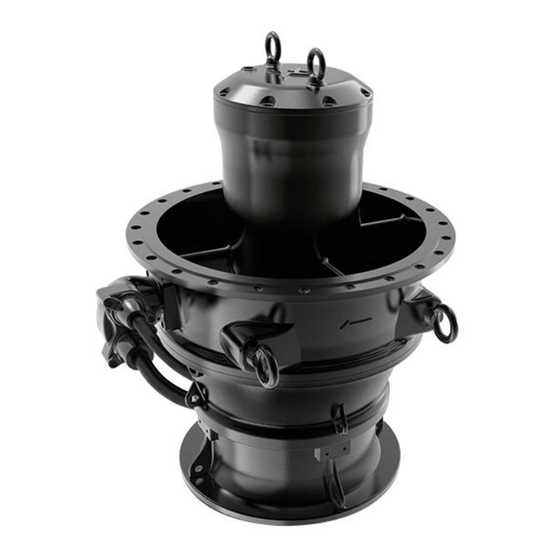
- Page 5 2.2 Notes 3. Product introduction The symbols and notes below may appear in 3.1 Product description Grundfos installation and operating instructions, safety instructions and service instructions. KPL pumps are submersible axial-flow propeller pumps. A blue or grey circle with a white graphical symbol indicates that an action must be taken.
- Page 6 3.3 Identification KPG pumps are gate pumps for submersible installation. 3.3.1 Type key Fix the extra nameplate supplied with the pump at the installation site or keep it in the cover of this booklet. Example of KPL: KPL. 600.19.6.T.50.9.L.40 Example of KPG: KPG. 600.19.6.T.50.9.E.40 Example of KWM: KWM.
- Page 7 4. Receiving the product 3.3.2 Nameplate Fix the extra nameplate supplied with the pump at the Make sure that the pump cannot roll or fall over. installation site or keep it in the cover of this booklet. 4.1 Handling the product •...
- Page 8 Lifting points When lifting the pump, use the right lifting points to keep the pump balanced. KPL and KWM: anti-rotation brackets KPL and KWM: lifting points Pos. Description Lifting point, bottom Lifting point, top Lifting point, top KPL and KWM: use the lifting bracket as the top lifting KPG: anti-rotation brackets point.
- Page 9 KPG: lifting with single wire (for transport) KPL and KWM: lifting with double wire, step 2 KPG: lifting with double wire, step 1 KPG: lifting with single wire connected to both lifting eyes (for installation) During installation, the KPG motor top is inserted into the gate flange.
- Page 10 5. Installation requirements 6. Mechanical installation of KPL and 5.1 Safety information and preparation DANGER • Pump installation in pits must be carried out by Electric shock specially trained persons. Death or serious personal injury • Work in or near pits must be carried out according ‐...
- Page 11 6.1 Requirement for free space below the pump The following table indicates the column pipe diameter (∅D) and the minimum free space allowed ØD (C) under the pump. For further information on installation, see fig. KPL: installation dimensions KWM: installation dimensions.
- Page 12 6.3 Pit construction, KPL and KWM <10° Pos. Description Screen ≤10°** ≥ D ≥ 4 x D ***Recommended value. The angle can change depending on pump size. For more information, contact Grundfos. ≤20°...
- Page 13 2400 2600 1300 2600 2600 2800 1400 2800 2800 3200 1600 3200 3200 3600 1800 3600 3600 Depending on construction, contact Grundfos 1000 4000 2000 4000 4000 1200 4800 2400 4800 4800 1400 5600 2800 5600 5600 1500 6000 3000...
- Page 14 6.4 Installing the column pipe 6.5 Installing the KPL and KWM pump 1. Fit a waterproof sealing between the mounting Make sure that the pump is aligned with the anti- flange and the concrete support. See fig. Position rotation brackets and cannot rotate when the impeller of the waterproof sealing.
- Page 15 6.6 Installing the cable suspension system in the column pipe If the pump is configured for side discharge, locate the cable inlet opposite the water outlet. Disruption in the direction of water flow may cause damage to the cable. To avoid cable damage, do not position the cable inlet in the column pipe near the water outlet.
- Page 16 Cable suspension system A cable suspension system is mandatory to avoid cable damage during operation. The figure below indicates a principle sketch only - the cable suspension system may be adapted to the specific pump type. 8 9 10 “B-B” Securing the cables to the lifting wire...
- Page 17 Pos. Description Shackle 1 Shackle 2 Turnbuckle Wire holder Wire rope Wire clamp Shackle 3 Power cable Wire rope Sensor cable Cable clamp 300 mm 500 mm Intermediate lifting ring (optional) Pos. Description Master link...
- Page 18 7. Mechanical installation of KPG DANGER Electric shock Death or serious personal injury ‐ Before installation, switch off the power supply and lock the main switch in position 0. ‐ Before working on the pump, switch off any external voltage connected to the pump.
- Page 19 7.1 Pit construction G.P.I KUM-A G.P.I G.P.I KUM-A KUM-A 1 gate and 1 pump 1 gate and 2 pumps Pump type Outlet diameter [mm] [mm] [mm] [mm] [mm] KPG.500 DN 500 1250 1950 1900 KPG.600 DN 600 1400 2100 2200 1000 KPG.700 DN 700...
- Page 20 7.2 Installing the KPG pump The pump must be connected to a motor- protective circuit breaker, such as MP 204. • Lift the pump horizontally by the lifting eyes on the A phase-sequence relay is recommended, outlet casing to install it in the gate. See fig. KPG: if the phase sequence of the power supply lifting with single wire connected to both lifting...
- Page 21 8.2 Wiring diagrams Direct-online-starting, one power cable Direct-online-starting, three power cables Direct-online-starting, two power cables Star-delta starting, one power cable...
- Page 22 In case a filter is not installed, please contact Grundfos. Pumps can be connected ideally to a Grundfos CUE, or a soft starter, depending on choice. When pumps are connected to a frequency converter pay attention to the motor insulation system.
- Page 23 9. Starting up the product 8.3.1 CUE or VFD The optional CUE or VFD, which is either a Grundfos The pump can be started by either direct-online- variable-frequency converter or a general variable starting, star-delta starting, soft starter or frequency frequency converter, offers better pump protection converter.
- Page 24 9.1 Preparations for starting up 1. Place the pump on a plain surface. 2. Secure the pump by using the lifting chain and a DANGER crane to prevent it from tilting. The pump must Rotating elements rest on the ground without any load on the crane. Death or serious personal injury See fig.
- Page 25 9.2 Startup Method 2 - Pump installed in a column pipe • Make sure the column pipe is not filled with water. WARNING • Make sure the pump is installed correctly. See Automatic startup section Installing the KPL and KWM pump.
- Page 26 10. Control functions 10.1 Sensors The table shows the difference between standard product and factory product variant (FPV) and the number of sensors. FPV sensors can be chosen individually. Number of sensors Sensor Type Standard Stator thermal protection Bi-metal Stator thermal protection Pt100 Terminal box moisture sensor Switch...
- Page 27 KPG: switches and sensors Key for figures: KPL, KWM and KPG: switches and sensors. Pos. Description Vibration sensor Thermal sensor Moisture switch Thermal switch Water-in-oil sensor (WIO)
- Page 28 See section Electrical connection The sensor must be connected to a Pt100 relay in the control cabinet, preferably to a Grundfos SM 113 or IO 113. The resistance of the sensor varies with the temperature. The table below indicates approximate values.
- Page 29 The sensors must be connected to a Pt100 relay in water content is outside the normal range (warning), the control cabinet, preferably to a Grundfos SM 113 or if the oil level is low (alarm). The sensor is fitted in or IO 113.
- Page 30 10.1.6 Pump vibration sensor (PVS 3) (only KPL 10.2.2 IO 113 and KWM) IO 113 forms the interface between a Grundfos storm- The PVS 3 sensor is a three-plane vibration sensor or wastewater pump with analog and digital sensors that monitors the vibration level to protect the pump and the pump controller.
- Page 31 11. Servicing the product 10.2.4 MP 204 The motor protector MP 204 is an electronic control 11.1 Safety instructions and requirements unit designed for monitoring and protecting motors, pumps, machines, cables and cable joints. DANGER The MP 204 monitors the following: Electric shock •...
- Page 32 2 mm, replace the be as follows: wear ring. • An O-ring is damaged. For further information, contact Grundfos or the • The cable entry is leaking. nearest authorised service workshop. If there is oil in the stator housing, the cause may be...
- Page 33 The pump is classified as contaminated if it has been used for toxic or contagious liquid. Before returning the product for service, contact Grundfos with details about the pumped liquid. Otherwise, Grundfos can deny to service the product.
- Page 34 13. Fault finding DANGER Electric shock Before diagnosing any fault, read and observe the Death or serious personal injury safety instructions in section Safety instructions and ‐ Before working on the product, make requirements. sure that the power supply has been switched off and it cannot be switched on unintentionally.
- Page 35 Fault Cause Remedy Check that the pipe connection is in order. The pump is not able to empty Check if the propeller or impeller clogged or jammed. the pit to the stop level. Check if the valves are open. The pump does not Clean the stop sensor.
- Page 36 14.1.3 Density and viscosity of the pumped liquid 14.2 Dimensions and weights Maximum density: 1000 kg/m For pump dimensions and weights, see data booklet on www.grundfos.com. Maximum kinematic viscosity: 1 mm /s (1 cSt). 14.2.1 Bending radius of cables When pumping liquids with a density or...
- Page 37 14.3 Minimum water levels The curves charts below show the relation between flow rate and recommended minimum submergence (S). [ft] [ft] KPL/KWM.600 KPL.500/KPL.20" KPL/KWM.24" KPL.600 E/L KWM.600 M/H KWM.24" M/H KPL.24" E/L KPL.500 L KPL.20" L 80 100 120 140 160 180 200 220 240 260 280 Q [l/s] 100 150 200 250 300 350 400 450 500 550 600 Q [l/s]...
- Page 38 [ft] [ft] KPL/KWM.1000 KPL/KWM.900 KPL/KWM.36" KPL/KWM.40" KPL.900 E/L KPL.36" E/L KPL.1000 E/L KPL.40" E/L KWM.900 M KWM.36" M KWM.1000 M KWM.40" M KWM.900 H KWM.36" H KWM.1000 H KWM.40" H 1000 1200 1400 1600 1800 2000 Q [l/s] 1200 1600 2000 2400 2800...
- Page 39 [ft] [ft] KPL/KWM.1600 KPL/KWM.1500 KPL/KWM.60" KPL/KWM.64" KPL.1600 E/L KPL.1500 E/L KPL.64" E/L 60" E/L KPL. KWM.1600 M KWM.64" M 500 1000 1500 2000 2500 3000 3500 4000 4500 5000 5500 6000 Q [l/s] 1000 2000 3000 4000 5000 6000 7000 8000 Q [l/s] 10000 20000 30000 40000 50000 60000 70000 80000...
- Page 40 14.3.1 KPL installation requirements M.W.L = C + S ØD M.W.L. M.W.L Installation dimensions, KPL pump, ACC installed Installation dimensions, KPL Requirements for installation ∅D [mm] C [mm] 1000 1200 1400 1500 1600 1800...
- Page 41 14.3.2 KPG installation requirements The requirements for installation are indicated in the table below. The figures show installation examples. Note: All distances in the table below are minimum dimensions All dimensions are subject to the actual site conditions or pump & gate design. Model Outlet diameter D [mm]...
- Page 42 2. If this is not possible, contact the nearest product means that it must be disposed of separately Grundfos company or service workshop. from household waste. When a product marked with this symbol reaches its end of life, take it to a...
- Page 43 The separate collection and recycling of such products will help protect the environment and human health. See also end-of-life information on www.grundfos.com/products/product-sustainability/ product-recycling.
- Page 44 Argentina Columbia Hong Kong Bombas GRUNDFOS de Argentina S.A. GRUNDFOS Colombia S.A.S. GRUNDFOS Pumps (Hong Kong) Ltd. Ruta Panamericana km. 37.500industin Km 1.5 vía Siberia-Cota Conj. Potrero Unit 1, Ground floor, Siu Wai industrial 1619 - Garín Pcia. de B.A.
- Page 45 Lithuania Serbia Turkey GRUNDFOS Pumps UAB Grundfos Srbija d.o.o. GRUNDFOS POMPA San. ve Tic. Ltd. Smolensko g. 6 Omladinskih brigada 90b Sti. LT-03201 Vilnius 11070 Novi Beograd Gebze Organize Sanayi Bölgesi Tel.: + 370 52 395 430 Tel.: +381 11 2258 740...
- Page 46 96770326 03.2024 ECM: 1386448 www.grundfos.com...
Need help?
Do you have a question about the KPL Series and is the answer not in the manual?
Questions and answers