
Related Manuals for Grundfos KPL


Summary of Contents for Grundfos KPL
- Page 1 GRUNDFOS INSTRUCTIONS KPL, KPG and KWM 11-700 kW, 50 Hz 11-800 kW, 60 Hz, DIN Installation and operating instructions Installation and operating instructions KPL, KPG and KWM http://net.grundfos.com/qr/i/96770326...
-
Page 2: Table Of Contents
Original installation and operating instructions Read this document before installing the These installation and operating instructions product. Installation and operation must describe Grundfos KPL, KPG and KWM pumps, 11- comply with local regulations and accepted 800 kW. codes of good practice. -
Page 3: Receiving The Product
• Control equipment, for example MP 204. • KPL and KWM: A column pipe with a seat ring and integrated anti-rotation brackets on which the pump is standing. The seat ring can be supplied with the pump as an installation accessory. -
Page 4: Lifting The Product
- The weight of the specific pump is stated on the pump nameplate. Lifting point, bottom DANGER Electric shock Death or serious personal injury - Never lift the pump by the power cables. Fig. 1 KPL and KWM: lifting points... - Page 5 Lifting point, top 3.2.1 Lifting with single or double wire KPL and KWM: Use the lifting bracket as the top Lifting with single wire lifting point. See fig. 4. KPG: Use two top lifting points. See fig. 5. Lifting point, centre (KPG) When installing KPG pumps horizontally, use the lifting points on the outlet casing, see fig.
-
Page 6: Mechanical Installation Of Kpl And Kwm
- Before beginning the installation, switch off the power supply and lock the main switch in position 0/Off. Fig. 7 KPL and KWM: lifting with double wire, - Before working on the pump, switch off step 1 any external voltage connected to the pump. - Page 7 Under-floor Above-floor installation installation Fig. 11 KPL: installation dimensions Under-floor Above-floor installation installation Fig. 12 KWM: installation dimensions 3.3.2 Installing the anchor bolts The anchor bolts should be installed before the pouring of the concrete as part of the construction work.
- Page 8 3.3.3 Guide for pit construction Screen Max. 10 ° Fig. 13 Schematic view of pit design...
- Page 9 2400 2600 1300 2600 2600 2800 1400 2800 2800 3200 1600 3200 3200 3600 1800 3600 3600 Depending on construction, contact Grundfos 1000 4000 2000 4000 4000 1200 4800 2400 4800 4800 1400 5600 2800 5600 5600 1500 6000 3000...
- Page 10 Death or serious personal injury casing (KPL) or outlet casing (KWM). The O-ring - Do not put your hands or any tools into seals between the pump and the seat ring, thus the pump inlet or outlet after the pump preventing backflow.
- Page 11 Cable suspension system Figure shows a principle sketch only - the cable suspension system may be adapted to the specific A cable suspension system is mandatory pump model. to avoid cable damage during operation. Lifting wire, detail D Cable clamps, distance Max.
-
Page 12: Mechanical Installation Of Kpg
3.4 Mechanical installation of KPG Observe all safety regulations at the installation site, for instance the use of DANGER blowers for fresh-air supply to the pit. Electric shock Observe the maximum cable bend radius, see Death or serious personal injury 11.1.4 Operating mode. -
Page 13: Electrical Connection
3.4.2 Installing the KPG pump 3.5 Electrical connection • Take particular care when installing the pumps, as the procedure is not similar to that of other Carry out the electrical connection in submersible pumps. accordance with local regulations. • To install the pump in the gate, lift the pump horizontally by the lifting eyes on the outlet The supply voltage and frequency are marked on the casing, see fig. - Page 14 3.5.2 Wiring diagrams Control cable Control cable Fig. 17 Direct-online-starting, one power cable Fig. 19 Direct-online-starting, three power cables Control cable Control cable Fig. 18 Direct-online-starting, two power cables Fig. 20 Star-delta starting, one power cable...
-
Page 15: Frequency Converter Operation
3.6.1 Requirements Control cable • The thermal protection of the motor must be connected. • The peak voltage and dU/dt must be in accordance with the table below. The values stated are maximum values supplied to the motor terminals. The cable influence has not been taken into account. -
Page 16: Starting Up The Product
U1 V1 W1 U2 V2 W2 pump or the cables. KPL and KWM: Wrong direction of rotation during operation when the pump is submerged will lead to damage to the pump and the column pipe. The pump will lift up from the seat ring and rotate in the Fig. - Page 17 • Make sure the pump is installed correctly. See Death or serious personal injury section 3.3.5 Installing the KPL and KWM pump. - Never stand under or next to the pump Proceed as follows: when it is hanging from a crane.
-
Page 18: Startup
5. Handling and storing the product 4.2 Startup WARNING 5.1 Handling the product Automatic startup When handling the product, observe the following Death or serious personal injury points: - Before manual starting or changeover to • Check that the lifting equipment is okay and see automatic control, make sure that no the lifting instructions. -
Page 19: Product Introduction
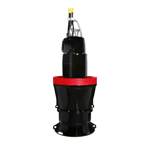
• filling and emptying water from dry docks and harbour. 6.2 General description Fig. 27 KWM pump KPL pumps are submersible axial-flow propeller KPG pumps are gate pumps for submersible pumps. installation. Fig. 28 KPG pump Pos. -
Page 20: Identification
7. Identification Code Description Explanation KPL, KPG and KWM pumps described in these 9 degrees installation and operating instructions are identified by the type designation stated in the order 11 degrees confirmation and other documentation supplied with 13 degrees the pump. -
Page 21: Nameplate
7.2 Nameplate The nameplate is located on the top cover of the pump. Fit the extra nameplate supplied with the pump at the installation site. DK-8850 Bjerringbro, Denmark Model: Serial No: Prod. No: Tmax: °C m /h IP68 Motor: Cos : Insul.class: year week... -
Page 22: Protection And Control Functions
Three Pt100 sensors are installed in the pump at the factory, but only one sensor is connected as a standard. It is not possible to connect all 3 stator thermal sensors if bearing sensors are also connected. 2 or 4 2 or 4 Fig. 30 KPL: switches and sensors Fig. 31 KWM: switches and sensors... - Page 23 2 or 4 Fig. 32 KPG: switches and sensors Legend for figures 30, and 32: Pos. Description Vibration sensor Thermal sensor Moisture switch Thermal switch Water-in-oil sensor (WIO)
- Page 24 See section 3.5 Electrical connection. The sensor must be connected to a Pt100 relay in the control cabinet, preferably a Grundfos SM 113 or IO 113. The resistance of the sensor varies with the temperature. The table below show approximate values.
- Page 25 The sensors must be connected to a Pt100 relay in water content is outside the normal range (warning), the control cabinet, preferably a Grundfos SM 113 or or if the oil level is low (alarm). The sensor is fitted in IO 113.
-
Page 26: Pump Control
IO 113 with SM 113 enables the following functions: 8.2 Pump control • protecting the pump against overtemperature KPL, KPG and KWM pumps can be controlled by the • monitoring the sensors for analog measurement following devices, which are available as... -
Page 27: Servicing And Maintaining The Product
9. Servicing and maintaining the 8.2.4 MP 204 The motor protector MP 204 is an electronic control product unit designed for monitoring and protection of motors, pumps, machines, cables and cable joints. 9.1 Safety instructions and requirements The MP 204 monitors the following parameters: •... - Page 28 2 mm, the cables are not sharply bent or pinched, and replace the wear ring. that the cable sheaths have no visual defects. If you have any questions, please contact Grundfos See section 9.2.5 Checking the cable entry.
-
Page 29: Spare Parts
Check that the rubber bushings and the washers toxic. correspond to the outside diameter of the cables. If you request Grundfos to service the pump, contact • Make sure there is no slack in the cable Grundfos with details about the pumped liquid before suspension, and that the cables are fixed to the returning the pump for service. -
Page 30: Fault Finding The Product
10. Fault finding the product Before attempting to diagnose any fault, read and observe the safety instructions in section 9.1 Safety instructions and requirements. DANGER Electric shock Death or serious personal injury - Before starting any work on the product, make sure that the power supply has been switched off and that it cannot be accidentally switched on. - Page 31 Fault Cause Remedy The pump does The pump is not able to Check the following and, if necessary, take corrective not stop. empty the pit to the stop action: level. • Is the pipe connection tight? • Is the propeller or impeller clogged? •...
-
Page 32: Technical Data
Depending on the installation type, the sound pressure level of the pump can be higher than 70 dB (A). 11.1.7 Turbulence optimiser (only with KPL and KWM) Turbulence optimisation is only possible if the pump is mounted in the column pipe size that the pump is intended for. -
Page 33: Water Level Requirements, Kpl
11.3 Water level requirements 11.4 Water level requirements, KPL The minimum requirement for free space and a guideline for the minimum water level are shown in the tables below. The figures show installation examples. All values for C, S and M.W.L. in the table below are minimum values. - Page 34 11.4.1 Water level requirements, KPG 7.5HP M.W.L Fig. 34 Installation example of KPG Requirements for installation Model Outlet diameter KPG.500 DN 500 1450 1250 3700 KPG.600 DN 600 1700 1050 1500 4200 KPG.700 DN 700 1700 1250 1500 4500 KPG.800 DN 800 1950 1400...
-
Page 35: Disposing Of The Product
1. Use the public or private waste collection service. 2. If this is not possible, contact the nearest Grundfos company or service workshop. The crossed-out wheelie bin symbol on a product means that it must be disposed of separately from household waste. - Page 36 Appendix Wiring diagrams IO113 SM113 G1 A1 G2 A2 K1 K2 R1 R2 PE - D1 D2 D3 D4 D5 D6 D7 D8 A Y B Reset IO 113 1 2 3 4 5 6 7 8 9 10 1112 9 10 11 12 13 14 P1 P2 P3 P4 P5 COM WIO...
- Page 37 IO113 SM113 G1 A1 G2 A2 K1 K2 R1 R2 PE - D1 D2 D3 D4 D5 D6 D7 D8 A Y B Reset IO 113 1 2 3 4 5 6 7 8 9 10 1112 9 10 11 12 13 14 P1 P2 P3 P4 P5 COM WIO COM1 B/S-L B/S-H...
- Page 38 IO 113 1 2 3 4 5 6 7 8 9 10 1112 P1 P2 P3 P4 P5 TP/B COM2 SM113 3.3K Fig. 3 Standard wiring diagram of IO 113 and SM 113 placed inside of the KPL and KWM pump...
- Page 39 1 2 3 4 5 6 7 8 9 10 1112 P1 P2 P3 P4 P5 TP/B COM2 SM113 Transient Barrier Fig. 4 Wiring diagram of IO 113 and SM 113 placed inside of the KPL, KPG and KWM pump with sensor options...
- Page 40 Designation Обозначение Název Betegnelse Tähistus Термичен Thermal switch Termospínač Termoafbryder Termolüliti превключвател Прекъсвач за Moisture switch Vlhkostní spínač Fugtafbryder Niiskuslüliti влажност Pt100 sensor Сензор Pt100 Snímač Pt100 Pt100-sensor Pt100 andur Заземителен Earth conductor Zemnicí vodič Jordleder Maandusjuhe проводник Water-in-oil Сензор за вода в Snímač...
- Page 41 ﻣﻳﺔ ﺍﻟﺗﺳ Benämning Označenie Tanımlama Betegnelse 名称 Termisk Tepelný ﻣﻔﺗ ﺎﺡ ﺣ ﺭﺍﺭﻱ Termik şalter Termisk bryter 热敏开关 brytare spínač Spínač ﻣﻔﺗ ﺎﺡ ﺍﻟﺭﻁﻭﺑ ﺔ Fuktbrytare Fuktbryter 湿度开关 vlhkosti sensörü Snímač Pt100 Pt100 ﺣﺳ ﺎﺱ Pt100-sensor Pt100-sensor Pt100传感器 Pt100 sensörü Uzemňovací...
- Page 42 Argentina China Hong Kong Bombas GRUNDFOS de Argentina S.A. GRUNDFOS Pumps (Shanghai) Co. Ltd. GRUNDFOS Pumps (Hong Kong) Ltd. Ruta Panamericana km. 37.500 Centro 10F The Hub, No. 33 Suhong Road Unit 1, Ground floor Industrial Garin Minhang District Siu Wai Industrial Centre 1619 Garín Pcia.
- Page 43 Malaysia Serbia Turkey GRUNDFOS Pumps Sdn. Bhd. Grundfos Srbija d.o.o. GRUNDFOS POMPA San. ve Tic. Ltd. 7 Jalan Peguam U1/25 Omladinskih brigada 90b Sti. Glenmarie Industrial Park 11070 Novi Beograd Gebze Organize Sanayi Bölgesi 40150 Shah Alam Phone: +381 11 2258 740...
- Page 44 96770326 1219 ECM: 1276977 www.grundfos.com...
Need help?
Do you have a question about the KPL and is the answer not in the manual?
Questions and answers