
Related Manuals for YOKOGAWA vigilantplant DPharp EJX Series


Summary of Contents for YOKOGAWA vigilantplant DPharp EJX Series
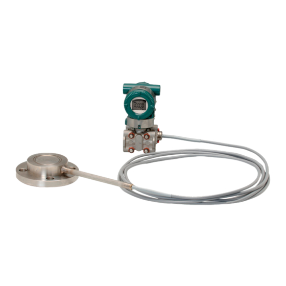
- Page 1 User’s Manual EJX118A and EJX438A Diaphragm Sealed Differential Pressure and Pressure Transmitters IM 01C25H01-01E IM 01C25H01-01E 3rd Edition Y okogawa Electric Corporation...
- Page 2 R e g a r d i n g T h i s M a n u a l ................. 1 - 1...
-
Page 3: Table Of Contents
CONTENTS Wiring ....................5-2 5.4.1 Loop Configuration ............... 5-2 (1) General-use Type and Flameproof Type ........5-2 (2) Intrinsically Safe Type ..............5-2 5.4.2 Wiring Installation ................. 5-2 (1) General-use Type and Intrinsically Safe Type ......5-2 (2) Flameproof Type ................. 5-3 Grounding .................... - Page 4 • All rights reserved. No part of this manual may be before you operate the instrument. reproduced in any form without Yokogawa’s written permission. • Yokogawa makes no warranty of any kind with NOTE regard to this manual, including, but not limited to, This manual describes the hardware configura- implied warranty of merchantability and fitness for a tions of EJX series transmitters.
- Page 6 Yokogawa. (f) Modification • The purchaser shall bear the responsibility for repair • Yokogawa will not be liable for malfunctions or costs, even during the warranty period, if the damage resulting from any modification made to this malfunction is due to: instrument by the customer.
- Page 7 Ex sono disponibili in inglese, tedesco e francese. Se si desidera ricevere i manuali operativi di prodotti Ex in lingua locale, mettersi in contatto con l’ufficio Yokogawa più vicino o con un rappresentante. Todos los manuales de instrucciones para los productos antiexplosivos de ATEX están disponibles en inglés,...
- Page 8 2. HANDLING CAUTIONS HANDLING CAUTIONS This chapter provides important information on how to handle the transmitter. Read this carefully before using the transmitter. EJX Series transmitters are thoroughly tested at the factory before shipment. When taking delivery of an instrument, visually check them to make sure that no damage occurred during shipment.
- Page 9 2. HANDLING CAUTIONS 2.4 Selecting the Installation 2.6 Waterproofing of Cable Location Conduit Connections The transmitter is designed to withstand severe Apply a non-hardening sealant to the threads to environmental conditions. However, to ensure that it waterproof the transmitter cable conduit connections. will provide years of stable and accurate performance, (See figure 5.8, 5.9 and 5.10.) take the following precautions when selecting the...
- Page 10 C & D. Class II, Division 2, Groups F & G and to operate. Please contact Yokogawa before making Class III, Division 1, Class I, Zone 2, Groups IIC, any repair or modification to an instrument.
- Page 11 • When installed in Division 1, “FACTORY • The instrument modification or parts replacement by SEALED, CONDUIT SEAL NOT REQUIRED.” other than authorized representative of Yokogawa Note 3. Operation Electric Corporation is prohibited and will void • Keep the “WARNING” nameplate attached to the Factory Mutual Intrinsically safe and Nonincendive transmitter.
- Page 12 • Enclosure: IP66 and IP67 by other than authorized representative of Note 2. Entity Parameters Yokogawa Electric Corporation is prohibited and • Intrinsically safe ratings are as follows: will void Factory Mutual Explosionproof Approval. Maximum Input Voltage (Vmax/Ui) = 30 V Maximum Input Current (Imax/Ii) = 200 mA c.
- Page 13 2. HANDLING CAUTIONS Class I, II, III, Division 1, Groups A, B, C, D, E, F, G EJX Series Pressure Safety Barrier Transmitters SupplyPuBar2D F0204-1.EPS IM 01C25H01-01E...
- Page 14 (CSA Intrinsically Safe or CSA by other than authorized representative of Explosionproof) for use in hazardous locations. Yokogawa Electric Corporation is prohibited and Note 1. For the installation of this transmitter, will void KEMA Intrinsically safe Certification. once a particular type of protection is Note 5.
- Page 15 • The instrument modification or parts replacement Note 4. Operation by other than authorized representative of • Keep the “WARNING” label attached to the Yokogawa Electric Corporation is prohibited and transmitter. will void Type of Protection “n”. WARNING: AFTER DE-ENERGIZING, DELAY 5 MINUTES BEFORE OPENING.
- Page 17 • The instrument modification or parts replacement by other than authorized representative of Model EJX Series pressure transmitters with Yokogawa Electric Corporation and will void optional code /SU2 can be selected the type of IECEx Intrinsically safe and type n certification.
- Page 18 Yokogawa Electric Corporation is prohibited and • Please take care to prevent water hammer and will void IECEx Certification. the like from inducing excessive pressures in pipes and valves.
- Page 19 3. COMPONENT NAMES COMPONENT NAMES EJX118A EJX438A Transmitter section* Transmitter section* *See below for details. *See below for details. Drain/vent plug Flushing connection ring Cover flange Diaphragm seal Cover flange with flushing connection ring Capillary tube Diaphragm seal (high pressure side) Diaphragm seal Diaphragm seal (low pressure side)
- Page 20 4. INSTALLATION INSTALLATION 4.1 Precautions IMPORTANT Before installing the transmitter, read the cautionary Please use a gasket with an inside diameter (ød) notes in Section 2.4, “Selecting the Installation that is greater than the diameter of the dia- Location.” For additional information on the phragm seal.
- Page 21 4. INSTALLATION IM 01C25H01-01E F02026EPS50mm minimumMinimum High I I nstall the sealed diaphragm...
- Page 22 4. INSTALLATION IMPORTANT The transmitter should be installed at least 600 mm below the high pressure (HP) process connection to ensure a positive head pressure of fill fluid. Pay special attention to vacuum applica- tions. If it can not be installed at least 600 mm below the HP process connection, please use the equation below: (P–P0) dHg...
- Page 23 4. INSTALLATION 4.4 Mounting the Flushing Con- nection Ring 4.4.1 Mounting to Pressure Detector Section The flushing connection ring is mounted to the pressure detector section as shown in Figure 4.6. At the factory shipment, the flushing connection ring is already assembled and attached to process detector section.
- Page 24 4. INSTALLATION 4.5 Affixing the Teflon Film The FEP Teflon option includes a teflon film and fluorinated oil. Before mounting the diaphragm seal to the process flange, affix the teflon film as follows: IMPORTANT (1) Position the diaphragm seal so that the diaphragm is in a upward position.
-
Page 25: Wiring
5. WIRING WIRING 5.1 Wiring Precautions 5.3 Connections of External Wiring to Terminal Box 5.3.1 Power Supply Wiring Connection IMPORTANT Connect the power supply wiring to the SUPPLY + • Lay wiring as far as possible from electrical and – terminals. When /AL is specified, also refer to noise sources such as large capacity transform- subsection 5.3.5. - Page 26 5. WIRING 5.3.4 Check Meter Connection Available only when /AL is not specified. Connect the check meter to the CHECK + and – terminals. (Use hooks.) • A 4 to 20 mA DC output signal from the CHECK + procedures. eters.
-
Page 27: Flameproof Type
5. WIRING (2) Flameproof Type Wire cables through a flameproof packing adapter, or use a flameproof metal conduit. Wiring cable through flameproof packing adapter. • Apply a non-hardening sealant to the terminal box connection port and to the threads on the flameproof packing adapter for waterproofing. -
Page 28: Operation
6. OPERATION OPERATION 6.1 Preparation for Starting Op- eration This section describes the operation procedure for the EJX118A as shown in Figure 6.1 when measuring liquid level in a closed tank, and EJX438A as shown in Figure 6.2 when measuring pressure in a tank. (a) Confirm that there is no leak in the connecting part of each diaphragm seal mounting flange. - Page 29 6. OPERATION Using the integral indicator • If the wiring system is faulty, the display stays blank. • If the transmitter is faulty, an error code is displayed. Self-diagnostic error on the integral indicator (Faulty transmitter) F0604.EPS IM 01C25H01-01E NOTE...
-
Page 30: Starting Operation
6. OPERATION [Example] The measuring range of 50 to 250 kPa; the actual measured value of 130 kPa. 130–50 Actual measured value= x 100=40.0% 250–50 (=10.4mA) Turn the screw to match the output signal to the actual measured value. 6.3 Starting Operation After completing the zero point adjustment, follow the procedures below to start operation. -
Page 31: Setting The Range Using The Range-Setting Switch
6. OPERATION 6) Press the range-setting push-button. The integral Vent screw indicator then displays “URV.SET.” When you loosen the vent screw, the accumulated liquid(or drain) (Note 1) 7) Apply a pressure of 50 kPa to the transmitter. will be expelled in the direction 8) Turn the external zero-adjustment screw in the of the arrow. -
Page 32: Maintenance
7. MAINTENANCE MAINTENANCE 7.1 Overview 7.2 Calibration Instruments Se- lection WARNING Table 7.1 lists the instruments that can be used to calibrate a transmitter. When selecting an instrument, Since the accumulated process fluid may be consider the required accuracy level. Exercise care toxic or otherwise harmful, take appropriate care when handling these instruments to ensure they to avoid contact with the body or inhalation of... - Page 33 0.1% or higher level, there may be difficulties in calibration to this level in the field. For calibration to the 0.1% level, contact Yokogawa representatives from which the instrument was purchased or the nearest Yokogawa office.
-
Page 34: Disassembly And Reassembly
7. MAINTENANCE 7.4 Disassembly and Reassembly IM 01C25H01-01E... -
Page 35: Replacing The Cpu Board Assembly
7. MAINTENANCE Mounting the CPU Assembly 7.4.2 Replacing the CPU Board Assembly 1) Connect the flat cable (with white connector) This subsection describes the procedure for replacing between the CPU assembly and the capsule. the CPU assembly. (See figure 7.3) 2) Connect the output terminal cable (with brown connector). -
Page 36: Troubleshooting
If any abnormality appears in the measured values, use the troubleshooting flow chart below to isolate and remedy the problem. Since some problems have complex causes, these flow charts may not identify all. If you have difficulty isolating or correcting a problem, contact Yokogawa service personnel. IM 01C25H01-01E... - Page 37 7. MAINTENANCE Connect BRAIN TERMINAL and check self-diagnostics. Does the self- diagnostic indicate problem location? Is power supply polarity correct? Contact Yokogawa service personnel. F0706.EPS IM 01C25H01-01E ata plcato YEPS v s specifiedt? Ares pwere...
-
Page 38: Alarms And Countermeasures
7. MAINTENANCE 7.5.3 Alarms and Countermeasures Table 7.3 Alarm Message Summary IM 01C25H01-01E... -
Page 39: General Specifications
However, this value (600 mm) may be affected by ambient temperature, operating pressure, fill fluid or material of the wetted diaphragm. Contact YOKOGAWA when the transmitter can not be installed at least 600 mm below the HP process connection. IM 01C25H01-01E... - Page 40 8. GENERAL SPECIFICATIONS NORMAL OPERATING CONDITION (Optional features or approval codes may affect limits.) Ambient Temperature Limits –40 to 60°C (–40 to 140°F) –30 to 60°C (–22 to 140°F) with LCD display (Note : The ambient temperature limits must be within the fill fluid operating temperature range, see table 8.1.) Process Temperature Limits See table 8.1.
- Page 41 8. GENERAL SPECIFICATIONS Load (Output signal code D and E) PHYSICAL SPECIFICATIONS 0 to 1290 for operation Process connections 250 to 600 for digital communication See the following table. Table 8.2 Flange size and rating Communication Requirements “ ” Process Size Flange (Safety approvals may affect electrical require-...
- Page 42 8. GENERAL SPECIFICATIONS Name plate and tag 304 SST Diaphragm seal section: Process Flange JIS S25C, JIS SUS304, or JIS SUS316 Capillary tube JIS SUS316 Protection tube JIS SUS304 PVC-sheathed (Max. operating temperature of PVC,100°C (212°F)) Fill fluid See table 8.1. Weight [EJX118A] Flush type: 16.1 kg (35.5 lbs)
-
Page 43: Model And Suffix Codes
8. GENERAL SPECIFICATIONS 8.2 MODEL AND SUFFIX CODES Instruction The model and suffix codes for EJX118A and EJX438A consist of two parts; a transmitter body section (I) and a diaphragm seal section (II). This specification sheet introduces these two parts separately. The transmitter body section is shown in one table, and the diaphragm seal section specifications are listed according to the process connection style. - Page 44 8. GENERAL SPECIFICATIONS [EJX438A] I. Transmitter body section EJX438A F0806.EPS IM 01C25H01-01E...
- Page 45 8. GENERAL SPECIFICATIONS II. Diaphragm seal section (Flush type) Process connection size: 3-inch (80 mm) / 2-inch (50 mm) EJX118A EJX438A F0807.EPS Model Suffix codes Description EJX118A ....Transmitter body section (I) EJX438A .
- Page 46 8. GENERAL SPECIFICATIONS II. Diaphragm seal section (Flush type) Process connection size: 1 1/2-inch (40 mm) EJX118A EJX438A F0808.EPS IM 01C25H01-01E...
- Page 47 8. GENERAL SPECIFICATIONS II. Diaphragm seal section (Extended type) Process connection size: 4-inch (100 mm) / 3-inch (80 mm) EJX118A EJX438A F0809.EPS IM 01C25H01-01E T08.01EPS ModelEJX118A...
- Page 48 8. GENERAL SPECIFICATIONS II. Diaphragm seal section (Combination type) Process connection size: Low pressure side; 4-inch (100 mm) · · · Extended type High pressue side; 3-inch (80 mm) · · · Flush type EJX118A F0810.EPS IM 01C25H01-01E 8-10 T0811.EPS ModelEJX118ADescription Suffix...
-
Page 49: Optional Specifications (For Explosion Protected Type)
Flameproof [No. IECEx CSA 05.0002] Flameproof for Zone1, Ex d IIC T6...T4 T0812.EPS Contact Yokogawa representative for the codes indicated as ‘-’. *1: Applicable for Electrical connection code 2, 4, 7, and 9. *2: Applicable for Electrical connection code 2 and 7. - Page 50 8. GENERAL SPECIFICATIONS Item Description Code Amplifier cover only Color change Painting Amplifier cover and terminal cover, Munsell 7.5 R4/14 Coating change Anti-corrosion coating Transistor output (sink type) Status output Contact rating: 10.5 to 30 V DC, 120 mA DC (max) Low level: 0 to 2 V DC Oil-prohibited use Degrease cleansing treatment...
- Page 51 8. GENERAL SPECIFICATIONS IM 01C25H01-01E 8-13...
-
Page 52: Dimensions
8. GENERAL SPECIFICATIONS 8.4 DIMENSIONS Transmitter body section [EJX118A] F0811.EPS IM 01C25H01-01E 8-14 Unit: mm (Approx.: inch) 137(5939) 89(3.50) 178(7101) - Page 53 8. GENERAL SPECIFICATIONS < Diaphragm seal section > Flush type Unit: mm (Approx.: inch) • No ring (flushing connection ring code 0) • With ring (flushing connection ring code 1, 2, 3, 4, A, B, C and D) Extended type *1: When wetted parts material code UW (titanium), value is 34 (1.34) *2: Indicates inside diameter of gasket contact surface...
- Page 54 8. GENERAL SPECIFICATIONS Unit: mm (Approx.: inch) Process flange size: 4 inch (100 mm) Process flange size: 3 inch (80 mm) Process flange size: 2 inch (50 mm) Process flange size: 1 1/2 inch (40 mm) T0815.EPS 8-16 IM 01C25H01-01E...
- Page 55 8. GENERAL SPECIFICATIONS Terminal Wiring Terminal Configuration Communication Power supply and output terminal SUPPLY – Check meter terminals (BT200 etc.) connection hook *1*2 External indicator (ammeter) terminal *1*2 connection hook CHECK – Status contact output terminal ALARM (when /AL is specified) Ground terminal *1: When using an external indicator or check meter, the internal resistance must be 10...
-
Page 56: Revision Record
REVISION RECORD Title: EJX118A and EJX438A Diaphragm Sealed Differential Pressure and Pressure Transmitters Manual No.: IM 01C25H01-01E Edition Date Page Revised Item Oct. 2004 — New publication Feb. 2005 · Add 2.9.2 ‘CSA CertificationX8 2.9.3 · Delete WARNING on non-incendive power supply8 ·...
Need help?
Do you have a question about the vigilantplant DPharp EJX Series and is the answer not in the manual?
Questions and answers