Advertisement
Quick Links
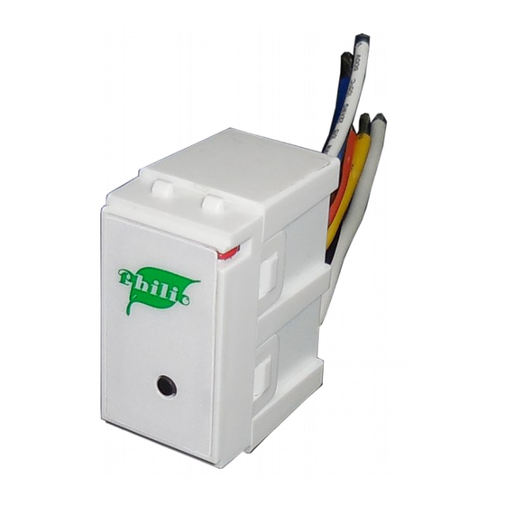
PAN09
TWO SPDT Switch module with meter
Introduction
This in-wall dual relay switch module is a transceiver which is a Z-Wave Plus
enabled device and is fully compatible with any Z-Wave
size design let the module can easily hide itself into the wall box and that will be
good for the house decoration.
There are many kind of application by using the module to switch AC power On
and Off, one main application is the light control. The new smart relay calibration
technology can reduce the inrush current caused by the load and let the module
work perfectly with many kind of light like incandescent, fluorescent and LED
light.
This in-wall switch module is able to detect Instant power wattage and overload
TM
TM
enabled network. Mini
1
current (6A with resistive load) of connected light or appliances. When detecting
overload state, the Module will be disabled and its On/Off button will be lockout
of which LED will flash quickly. However, disconnect and re-connect the Module
will reset its overload condition to normal status.
Safety Precautions and Installation
Avoid installing the unit in storming or raining weather.
Be sure to isolate or switch off power source before installing or
maintenance.
Do ensure that the power supply circuit protected by a 16A circuit breaker
or suitable equivalent fuse.
IMPORTANT
Installation must be performed by skilled technicians who are informed
about the standards and technical requirements of the appliance and its
proper installation.
Check your local codes as they apply to your situation. If the house wiring
is of aluminum, consult with an electrician about proper wiring methods.
Before proceeding with the installation, TURN OFF THE POWER TO THE
LIGHTING CIRCUIT AT THE CIRCUIT BREAKER OR FUSE BOX TO AVOID
ELECTRICAL SHOCK.
Specification
Rated Voltage
100-240VAC 50Hz/60Hz 5A
Maximum Load
5A (230Vac/120Vac) (Resistive load)
Range
Minimum
40m indoor
100m outdoor line of sight
Advertisement

Related Manuals for Philio PAN09


Summary of Contents for Philio PAN09
- Page 1 PAN09 current (6A with resistive load) of connected light or appliances. When detecting TWO SPDT Switch module with meter overload state, the Module will be disabled and its On/Off button will be lockout of which LED will flash quickly. However, disconnect and re-connect the Module will reset its overload condition to normal status.
- Page 2 Cause of Failure Recommendation The Switch not working and 1. The Switch is not 1. Check power connections Fig 1. PAN09 Assembling LED off connect to the Main 2. Don’t open up the Switch and For Instruction to http:// www.philio-tech.com power send it for repair.
- Page 3 In the front of casing, there is an on/off button with LED indicator below which is used to toggle switch on and off or carry out inclusion, exclusion, reset or association. When first power is applied, its LED flashes on and off alternately and repeatedly at 0.5 second intervals.
- Page 4 IDs are excluded. LED 0.5s On, 0.5s Off Normal Whatever we switch On and off of the PAN09 by On/Off button (Enter auto inclusion) or RF command, the LED will lights up 1 second and then off. No node ID...
- Page 5 Learning When PAN09 is in learning mode, LED flashes on and off alter- nately and repeatedly at 0.5 second intervals. 1. Put in wall switch into a wall box and connect the AC power wire L, N to Overload When overload state occurs, the Switch is disabled of which PAN09 connector L, N.
- Page 6 Configuration parameter 3=2 Report ON when relay 1 ON and relay 2 Report OFF when relay 1 OFF Configuration parameter 3=2 switch ON and OFF of relay 1 Configuration parameter 3=3 Report ON when relay 2 ON Report OFF when relay 2 OFF Configuration parameter 3=3 switch ON and OFF of relay 2 Basic Get Command: [Command Class Basic, Basic Get] Basic Report Command:...
- Page 7 For group 3, the Switch will report (1) ON/OFF status of Relay2 (2) Instant Power Consumption (Watt) of Relay2 (3) Accumulated Power Consumption When PAN09 detect the overload, it will send Alarm Report to the correspond (KWh) of Relay2 to Z-Wave Controller.
- Page 8 Example: Accumulated power consumption (KWh) = (Meter Value 2*65536) + (Meter Meter Value 1 = 0x00 (W) Value 3*256) + (Meter Value 4) = 800.35 (KWh) Meter Value 2 = 0x00 (W) Meter Value 3 = 0x03 (W) 2-2-3 Clearing accumulated power consumption Meter Value 4 = 0xEA (W) Whenever re-start counting the accumulated power consumption is needed, Meter(W) = Meter Value 3 *256 + Meter Value 4 = 100.2W...
- Page 9 If endpoint set to 2 and PAN09 will reply state of Relay2. AC load current = (Meter Value 1*256) +(Meter Value 2)= 2.89 (A) If endpoint set to 3 and PAN09 will reply ON(0xFF) either Relay 1 or Relay2 is 2-2-6 load power factor (PF) ON, report OFF(0x00) when both Relay 1 and Relay2 OFF.
- Page 10 1 or switch Relay2 ON/OFF by setting endpoint to 2 or switch both Relay1 and 0x25) Relay2 ON/OFF by setting endpoint to 3. Command =0x02 (Switch_Binary_Get = 0x02) The example of the command show that switch off relay1 of PAN09 Below is the example show PAN09 report to last command COMMAND_CLASS_MULTI_CHANNEL COMMAND_CLASS_MULTI_CHANNEL MULTI_CHANNEL_CMD_ENCAP...
- Page 11 (Bit Address+Destination End Point = 0x01) 2-3-3 METER_SUPPORTED_GET: Command Class = 0x32 (Command_Class_Meter_V3 = 0x32) This command is to ask the endpoint of PAN09 what kind of meter data can be Command =0x04 (Meter_Supported_Report = 0x04) reported. Parameter 1 = 0x81 (Meter Reset =1 ,...
- Page 12 0x05) = command inquirer’s Endpoint value) 2-3-5 METER_GET: Using meter get command to get the KWH, W, V, I, PF from endpoint of PAN09 Command Class = 0x32 (Command_Class_Meter_V3 = 0x32) 2-3-5-1 Get KWH from endpoint Command =0x02 (Meter_Report = 0x02)
- Page 13 (Meter_Get = 0x01) Parameter 1 = 0x10 (Scale = W = 0x02) COMMAND_CLASS_MULTI_CHANNEL MULTI_CHANNEL_CMD_ENCAP PAN09 Instant Power Consumption (W) Report example: Source End Point = 0x05 (this is the endpoint of command inquirer, here we assume endpoint is 5,if the COMMAND_CLASS_MULTI_CHANNEL inquirer doesn’t support multi Channel this...
- Page 14 Parameter 1 = 0x28 (Scale = A = 0x05) Command Class = 0x32 (Command_Class_Meter_V3 = 0x32) Command =0x02 (Meter_Report = 0x02) PAN09 AC load current (I) example: Parameter 1 = 0xA1 (Scale Bit2 = 1 ,Rate Type = 0x01, COMMAND_CLASS_MULTI_CHANNEL Meter Type=0x01) MULTI_CHANNEL_CMD_ENCAP Parameter 2 = 0x22 (Precision = 1,Scale Bit1Bit0 =...
- Page 15 (Meter_Get = 0x01) Watt Meter 0x00- 0:Disable Parameter 1 = 0x30 (Scale = PF = 0x06) Report 0x7FFF Report W Period 1~0x7FFF: 720*5s=3600s=1 PAN09 power factor report example: hour 0x00- 10min 0:Disable COMMAND_CLASS_MULTI_CHANNEL Meter 0x7FFF Report KWH MULTI_CHANNEL_CMD_ENCAP Report 1~0x7FFF:...
- Page 16 10000 of KWH for 3-1 Watt Meter Report Period: Load If the setting is configured for 1hour (set value =720), the PAN09 will report its Caution instant power consumption every 1 hour to the node of correspond Group. Relay 1 : Control relay...
- Page 17 Meter_Get Relay1 W1+Relay2 W2 setting value is 600 (6A), when the load current of Relay1 over this value, Watt PAN09 will send current meter report to the node of correspond Group, the Meter_Get Relay1 and Relay2 are the same Voltage Range of the setting value is from 10 to 600, and the default value is 600 (6A).
- Page 18 This is a warning when the KWh of load over the preset threshold value, If the 3-10-2 5% : When the differential value of Watt is over 5%, PAN09 will send a setting value is 10000, when the Accumulated Power Consumption of Relay1 or meter report to the associated group.
- Page 19 * COMMAND_CLASS_POWERLEVEL purchased. They can take this product for environmental safe recycling. * COMMAND_CLASS_SWITCH_BINARY Philio Technology Corporation * COMMAND_CLASS_BASIC 8F., No.653-2, Zhongzheng Rd., Xinzhuang Dist., New Taipei City * COMMAND_CLASS_SWITCH_ALL 24257,Taiwan(R.O.C)
- Page 20 If this equipment does cause harmful interference to radio or television reception, which can be determined by turning the equipment off and on, the user is encouraged to try to correct the interference by one of the following measures: • Reorient or relocate the receiving antenna. •...
Need help?
Do you have a question about the PAN09 and is the answer not in the manual?
Questions and answers