Sungrow SBR096, SBR128, SBR160, SBR192, SBR224 Manual
- User manual (60 pages) ,
- Quick installation manual (29 pages) ,
- Manual (2 pages)
Advertisement
- 1 About This Manual
- 2 Product Description
- 3 Unpacking and Storage
-
4
Mounting
- 4.1 Safety during Mounting
- 4.2 Location Requirements
- 4.3 Installation Environment Requirements
- 4.4 Installation Clearance Requirements
- 4.5 Installation Tools
- 4.6 PE Cable Preparation
- 4.7 Assembling the SUNCLIX Connector
- 4.8 Assembling the MC4 Connectors (Optional)
- 4.9 Assembling the Communication Connector
- 4.10 Installing the Battery
- 5 Commissioning
- 6 Decommissioning the Battery
- 7 Battery Augmentation
- 8 Troubleshooting
- 9 Maintenance
- 10 Technical Data
- 11 Quality Assurance
- 12 Contact Information
- 13 Safety Instructions
- 14 Documents / Resources
About This Manual
The manual mainly describes the product information, guidelines for installation, operation and maintenance. The manual cannot include complete information the system (i. e. the PCS), just the battery. The reader can get additional information about other devices at www.sungrowpower.com or on the webpage of the respective component manufacturer.
Validity
This manual is valid for the following battery models:
- SBR096
- SBR128
- SBR160
- SBR192
- SBR224
- SBR256
They will be referred to as "battery" hereinafter unless otherwise specified.
Target Group
This manual is intended for battery owners who will have the ability to interact with the battery and qualified personnel who are responsible for the installation and commissioning of the battery. Qualified personnel should have the following skills:
- Training for installation and commissioning of electrical system, as well as dealing with hazards
- Knowledge of the manual and other related documents
- Knowledge of the local regulations and directives
How to Use This Manual
Read the manual and other related documents before performing any work on the battery.
Documents must be stored carefully and be available at all times.
Images in this manual are for reference only. The actual product received may differ.
Contents may be periodically updated or revised due to the product development. It is probably that there are changes of manual in the subsequent battery edition. The latest manual can be acquired via visiting the website at support.sungrowpower.com.
Symbols
Important instructions contained in this manual should be followed during installation, operation and maintenance of the PCS. They will be highlighted by the following symbols.

Indicates a hazard with a high level of risk that, if not avoided, will result in death or serious injury.

Indicates a hazard with a medium level of risk that, if not avoided, could result in death or serious injury.

Indicates a hazard with a low level of risk that, if not avoided, could result in minor or moderate injury.

Indicates a situation that, if not avoided, could result in equipment or property damage.
 Indicates additional information, emphasized contents or tips that may be helpful, e.g. to help you solve problems or save time
Abbreviation
BMS: Battery Management System
BMU: Battery Management Unit
CAN: Controller Area Network
CMU: Battery Cluster Management Unit LFP: Lithium iron phosphate
PCS: Power Conversion System
SOC: State of Charge
Product Description
Product Introduction
Brief Introduction
The battery is designed for residential energy storage systems. The inbuilt battery management system monitors its operation and prevents the battery from operating beyond the specified limitations.
This product is a high-voltage battery system with an operating voltage range between 150 V ~ 584 V. A battery system consist of 3 to 8 individual battery modules connected in series. Max.4 batteries can be connected in parallel to compatible PCS. Please refer to PCS manual for the compatibility details.

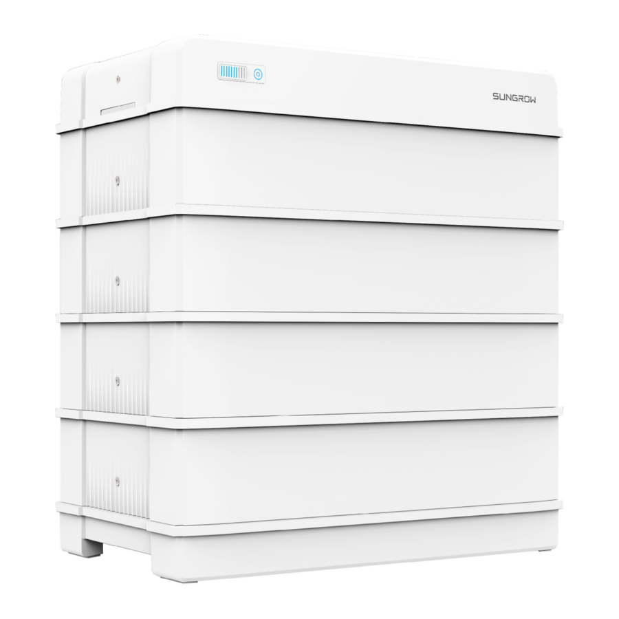
figure 2-1 Product overview
Images are for reference only. The actual products received may differ.
table 2-1 Design of the product
| Position | Designation |
| A | LED Indicator LED indicator include the SOC indicator and the status indicator. The status indicator is also used as the power button. LED indicator indicates the SOC value and status of the battery. |
| B | Nameplate The nameplate clearly indentifies the product. The nameplate must remain permanently attached to the product. You will find the following information on the nameplate:
|
| C | DC circuit breaker |
Major Components

Images are for reference only. The actual products received may differ.
| Name | Designation | ||
| A | Base | ||
| B | Battery module | ||
| C | Top cover | ||
| D | Switch gear | ||
| E | Side cover | ||
table 2-2 Configuration Table
| No. | Model | Base | Battery module | Top cover | Switch gear | Side cover |
| 1 | SBR096 | 1 | 3 | 1 | 1 | - |
| 2 | SBR128 | 1 | 4 | 1 | 1 | 1 |
| 3 | SBR160 | 1 | 5 | 1 | 1 | 2 |
| 4 | SBR192 | 1 | 6 | 1 | 1 | 3 |
| 5 | SBR224 | 1 | 7 | 1 | 1 | 4 |
| 6 | SBR256 | 1 | 8 | 1 | 1 | 5 |
Terminal Description
All electrical terminals are located at the switch gear.

Images are for reference only. The actual products received may differ.
| No. | Label | Description | ||
| 1 | P- | The system negative terminal, connected to the PCS negative terminal | ||
| 2 | P+ | The system positive terminal, connected to the PCS positive terminal | ||
| 3 | COMM | To enable the communication between the PCS and the battery | ||
| 4 |  | Grounding terminal, connected to the ground | ||
| 5 | DC circuit breaker | To connect/disconnect the DC circuit, for power-on, power-off, and short-circuit protection | ||
Symbols on the Product
| Symbol | Explanation |
 | Pay attention to the danger. Do not operate this product in the live status! |
 | No open flames Do not expose to flame, incinerate, puncture, or impact. |
 | Electric shock hazard Serviced by qualified personnel only. Out of reach from children. |
 | TÜV mark of conformity |
 | TÜV mark of conformity |
 | CE mark of conformity EU/EEA Importer |
 | UKCA mark of conformity |
 | Do not dispose in trash. Compacting a lithium ion battery is dangerous as it can explode. |
 | Please recycle this lithium ion battery. Do not discard. |
 | Read the user manual before maintenance! |
 | This is a protective grounding terminal, which should be grounded securely to protect the safety of operators. |
LED Indicator
LED indicators include the SOC indicator and the status indicator. The status indicator is also used as the power button.
SOC Indicator
The SOC indicator indicates the current SOC value of the battery. One bar indicates the SOC value of 10%.

Status Indicator
The Status indicator indicates the current state of the battery.
| LED color | LED indicator | LED state | Definition | ||
 | Blue | ON | Normal operation (without fault) | ||
| Slow blink Period: 2 s | The battery is at power-on or standby state or firmware update state(without fault). | ||||
| Fast blink Period: 0.5 s | Battery self-test in process. | ||||
 | Red | ON | A system fault has occured. | ||
| Blink | The battery is at power-on or standby state (with primary fault). | ||||
Images are for reference only. The actual products received may differ.
The status indicator can be used to power on the battery.
| Operation | Definition | |
| Press and hold for less than 2 seconds | To power on the battery* | |
*The start mode is black start, please refer to " Commissioning Procedure" for details.
Unpacking and Storage
Unpacking and Inspection
The product is thoroughly tested and strictly inspected before delivery. Nonetheless, damage may still occur during shipping. For this reason, please conduct a thorough inspection after receiving the product.
- Check the packing case for any visible damage.
- Check the scope of delivery for completeness according to the packing list.
- Check the inner contents for damage after unpacking.
Contact SUNGROW or the transport company in case of any damage or incompleteness, and provide photos to facilitate services.
Do not dispose of the original packing case. It is recommended to store the device in the original packing case when the product is decommissioned.
After receiving the product, check whether the appearance and structural parts of the device are damaged, and check whether the packing list is consistent with the actual ordered product. If there are problems with the above inspection items, do not install the device and contact your distributor first. If the problem persists, contact SUNGROW in time. If any tool is used for unpacking, be careful not to damage the product.
Scope of Delivery

| Item | Name | Quantity | ||
| A | Base | 1 | ||
| B | Battery module | 3 - 8 | ||
| C | Top cover | 1 | ||
| D | Switch gear1 | 1 | ||
| E | Bracket | 1 | ||
| F | Side cover | 3 - 8 | ||
| G | Communication connector | 1 | ||
| H | M5*125 hex socket screw(optional) | 1 | ||
| I | Foot | 4 | ||
| J | M5*14 hex socket screw2 | 14 - 24 | ||
| K | Expansion plug set | 2 | ||
| L | M5 screw sets2 | 6 | ||
| M | M6 fender washer2 | 5 | ||
| N | SUNCLIX connector or MC4 Connector | 1 | ||
| O | OT terminal | 1 | ||
| P | Communication cable fastening tool | 1 | ||
| Q | Documents | 1 | ||
- Images in this manual are for reference only. The actual product received may differ.
- The number of parts marked with " 2 " is greater than required. Please refer to the installation steps for the specific quantity needed.
Storage
Proper storage is required if the battery is not installed immediately.
- Store the battery in the original packing case with the desiccant inside.
- Preferably, keep the temperature in the range of 15℃ - 25℃. Store the battery within the temperature range of -10℃ to 35℃ for no more than 6 months.
- The storage relative humidity must be always between 0 and 95%, non-condensing.
- Store the battery in a clean and dry place, without exposure to sunlight and rain. The storage location must be free of harmful gases, flammable/explosive products and corrosive chemicals. The battery should be prevented from mechanical impact, high pressure, high-intensity magnetic field and direct exposure to sunlight.
- Pay attention to the harsh environment, such as sudden cooling/heating and collision, to avoid damage to the battery.
- The number of stacking layers of battery modules with package must not exceed 6. It is strictly forbidden to directly stack batteries without package.
- Regularly inspect the package for damage and insect bites. If any damage is found, the product should be replaced immediately.
- The packing should be upright.
- If stored for more than 6 months under the specified conditions, the battery needs to be charged once, until the system SOC is 50% - 80%. Preferably, use an PCS for forced charging.
If the battery is stored over one year, 5% - 10% of the capacity may lose irreversibly.
Mounting
Safety during Mounting
This product or system must be operated by professionals!
Failure to follow the safety instructions in this manual or operation of this product or system by non-professionals may cause severe personal injury or major property damage.
Strictly follow local relevant standards and requirements in the whole process of installation.
Location Requirements
Select an optimal mounting location for safe operation, long service life and expected performance.
The battery with IP55 can be installed both indoors and outdoors.
Install the battery in a place convenient for electrical connection, operation, and maintenance.
Installation Environment Requirements
- The installation environment must be free of inflammable or explosive materials.
- The location should be not accessible to children.
- The ambient temperature is recommended to be between 10℃ and 30℃. Please refer to "Technical Data" for the maximum operation temperature range.
- The relative humidity must be always between 0 and 95%, non-condensing.
- Avoid direct exposure to sun, rain and snow.
- The battery should be well ventilated. Ensure air circulation.
Installation Clearance Requirements
- Reserve enough clearance around the battery to ensure sufficient space for heat dissipation.

- In case of multiple batteries, reserve specific clearance between the batteries.


Installation Tools
Installation tools include but are not limited to the following recommended ones. If necessary, use other auxiliary tools on site.
table 4-1 Tool specification


PE Cable Preparation
Additional grounding cable is prepared by customers.
table 4-2 Cable requirements
| Type | Specification |
| Complying with 1000V and 105℃ standard | 4–6 mm 2 |
Prepare the cable and OT/DT terminal.

Assembling the SUNCLIX Connector
During assembly, be careful not to contaminate, pull out, or shift, the seal in the cable gland. A contaminated or shifted seal impairs strain relief and leak tightness.

figure 4-1 SUNCLIX Connector Components
- Spring
- Sleeve
- Insert
- Cable gland
- Strip the insulation from the cable by 10mm - 15 mm.

- Pry the connection open and pull the sleeve and the insert apart.

- Insert the stripped cable into the cable gland up to the stop. The stranded wire can be seen inside the spring. Press the spring down until it audibly snaps into place.

- Push the insert into the sleeve and tighten the cable gland (torque 2 N·m).


Assembling the MC4 Connectors (Optional)
To ensure IP65 protection, use only the supplied connector.
- Strip the insulation from the cable by 7 mm - 8 mm.
![]()
- Assemble the cable ends with the crimping pliers.
![]()
- Positive crimp contact
- Negative crimp contact
- Lead the cable through cable gland, and insert the crimp contact into the insulator until it snaps into place. Gently pull the cable backward to ensure firm connection. Tighten the cable gland and the insulator (torque 2.5 N•m to 3 N•m).
")


")
Assembling the Communication Connector
If the communication connector received is G2, please skip this step.
- Unscrew the swivel nut from the connector.
![]()
- Remove the inner rubber gasket.
![]()
- Insert the RJ45 plug into the front plug connector until there is an audible click, and install the rubber gasket.
![information]() It is recommended that the RJ45 connector be exposed 9 - 11mm outside the communication connector.
It is recommended that the RJ45 connector be exposed 9 - 11mm outside the communication connector.

- Tighten the swivel nut.


Installing the Battery
Assemble the battery on a flat surface. The SBR128 mounting will be used as an example.
- Install the feet of the battery.
Method 1

Method 2

- Align the base with the wall, and keep a distance of 30 mm to 45 mm between the base and the wall. Mark the hole positions of the mounting bracket with a marker according to the required layout of holes.
![information]() Mark the hole positions along a line vertical to the measurement baseline. The feet of the base have been installed already.
Mark the hole positions along a line vertical to the measurement baseline. The feet of the base have been installed already.

- Upper surface of the base
- Base(front view)
- Measurement baseline
- Base(top view)
- Drill the holes according to the marked positions, and install the expansion sleeves.
![]()
Goggles and gloves are necessary when drilling holes for protection. Shield the battery during drilling. After drilling, clean up debris in time.

- Position the base maintaining the required distance from the wall.

- Place each battery module on top of the base.
![information]() When carrying the battery module, always be aware of its weight of 33 kg.
When carrying the battery module, always be aware of its weight of 33 kg.

- Fix the battery modules with the included screws.

- Connect the switch gear to the base.
![information]() Ensure that the DC circuit breaker is disconnected.
Ensure that the DC circuit breaker is disconnected.

- Fix the switch gear with the provided M5 screw or stud.
![information]() When 4 or more than 4 battery modules are installed in one base, M5 screw set is required to secure the switch gear. The stud is mounted on the top of battery module.
When 4 or more than 4 battery modules are installed in one base, M5 screw set is required to secure the switch gear. The stud is mounted on the top of battery module.

- Fix the battery to the wall.
![information]() The bracket is mounted on the top battery module. The mounting position can be fine-tuned through oval holes in the back. Goggles and gloves are necessary when drilling holes for protection. Shield the battery during drilling. After drilling, clean up debris in time.
The bracket is mounted on the top battery module. The mounting position can be fine-tuned through oval holes in the back. Goggles and gloves are necessary when drilling holes for protection. Shield the battery during drilling. After drilling, clean up debris in time.

- Connect the harness.

For communication between the battery and the PCS, after connecting the communication cable to the COMM port, use the communication cable fastening tool to tighten the cable clockwise. Then conncet to the PCS using the other end of the communication cable. Strip the insulation layer of the communication cable with a wire stripper, and lead the corresponding CAN1_H/CAN1_L signal cable out. Cut off the redundant signal cable and warp it with a heat-shrink tubing. Signal cable 1 white and orange cable is used as CAN1_H; and signal cable 2 orange cable is used as CAN1_L.

![]()
Please ensure that the MC4 cable are connected to same terminals, as shown below.
![]()
- Place the top cover and fix it with the screws provided.

- (Optional) Install the side covers.


When 4 or more than 4 battery modules are installed in one base, side covers are required
Commissioning
Inspection before Commissioning
Check the following items before starting the battery:
- Check that the battery system has been installed completely.
- Check that the appearance of the battery system is intact.
- Check that the battery system output wiring harness is correctly connected to the positive and negative terminals of the battery and PCS to avoid misconnection and reverse connection.
- If a combiner box is used, check whether the connection between the battery and the combiner box and the connection between the combiner box and the PCS is complete, and whether the positive and negative terminals are correctly connected.
Commissioning Procedure
If all of the items mentioned above meet the requirements, proceed as follows to start up the battery for the first time.
- Connect all the switches on the AC and DC sides of the PCS.
- Manually connect the DC breaker on the right side of the battery so that the BMS enters the self-test state. The status indicator blinks in blue. Wait until the indicator is steady on in blue, which indicates that the battery system is powered on and runs normally.
![information]() Black Start: If the communication is established for the first time between the battery and the PCS, and the PCS has no DC power supply and no AC power supply. Manually connect the DC breaker on the right side of the battery so that the BMS enters the self-test state. The status indicator blinks in blue. Ten seconds later, press and hold the status indicator for less than 2 seconds. Wait until the indicator is steady on in blue, which indicates that the battery system is powered on and runs normally.
Black Start: If the communication is established for the first time between the battery and the PCS, and the PCS has no DC power supply and no AC power supply. Manually connect the DC breaker on the right side of the battery so that the BMS enters the self-test state. The status indicator blinks in blue. Ten seconds later, press and hold the status indicator for less than 2 seconds. Wait until the indicator is steady on in blue, which indicates that the battery system is powered on and runs normally.

- Close the protective cover.


During commissioning, if there is a short-circuit fault in the battery system, disconnect the power cable between the switch gear and the PCS, check the battery system wiring, and eliminate the short-circuit fault point. Execute step 2, check whether there is a fault in the battery (the indicator light is red), and obtain fault information through iSolarCloud to contact SUNGROW to repair the battery system.
First Power-on Calibration
The battery can only be connected to PCS produced by SUNGROW, as listed below:
- Three-phase model: SH5.0RT, SH6.0RT, SH8.0RT, SH10RT.
- Single-phase model: SH3.0RS, SH3.6RS, SH4.0RS, SH5.0RS, SH6.0RS.
Pay attention the PCS firmware version should be same that is illustrated in PCS manuals.
When the battery works with PCS, it automatically calibrates every half year. Calibration is done automatically by batteries and PCS given that there is electricity in the grid or PV modules to charge and discharge batteries.
- The battery automatically issues discharge instructions to PCS, which discharge the battery to 0% SOC at rated current.
- PCS charges the battery to 100% the capacity to complete the calibration of battery capacity and SOH.
During calibration, the discharge cut-off function and charge-discharge current limiting function are disabled.
Decommissioning the Battery
Decommission the battery in the system after the PCS is decommissioned. Proceed as follows to decommission the battery.
- Press and hold the power button for 4 seconds until the DC breaker on the right side of the battery is disconnected.
- One minute after the DC breaker is disconnected, disconnect all cables between the battery and other devices.
Contact SUNGROW to dispose of the battery.
If a combiner box is used, power off the DC and AC sides of the PCS, and disconnect MCBs of all battery RACKs before operating the battery system.
Battery Augmentation
Battery charging and discharging may take a long time. So before adding new battery modules, please finish charging and discharging the battery system on site remotely referring to brief introduction of battery augmentation on the support website to avoid the installer waiting on site.
Before adding new battery modules, make sure to follow the document mentioned above to charge and discharge batteries on site by iSolarCloud App. After setting, the battery system on site will be automatically charged and discharged, so that the SOC of batteries on site will be consistent with the battery modules to be added. Otherwise, the battery system may not operate normally after the new modules are added, and the problems caused will not be covered by the warranty
Troubleshooting
Once the battery fails, the fault information can be displayed on the App interface. If the PCS is equipped with an LCD screen, the fault information can be viewed on it. The fault codes and troubleshooting methods of all battery are detailed in the table below. The device you purchase may only contain some of the fault information, and when the battery fails, you can check the corresponding information through the fault codes from the mobile App.
| Alarm ID | Alarm Name | Corrective Measures |
| 703, 707, 708, 711, 712, 715, 717, 732– 737, 739, 832–837, 839, 844, 864, 866– 868, 870 | Battery fault |
|
| 932–935, 937, 939, 964 | Battery alarm | Generally, the battery can automatically recover. In case the alarm persist for a long time:
|
Maintenance
When adding new battery modules for capacity expansion, please contact SUN- GROW and follow the instruction released by SUNGROW. Otherwise, the system performance will be affected or even cannot operate properly.
Below is the recommended maintenance cycle. The actual maintenance cycle should be adjusted according to the specific installation environment of this product.
The power station scale, installation location and on-site environment affect the maintenance cycle of this product. In sandy or dusty environments, it is necessary to shorten the maintenance cycle and increase the frequency of maintenance.
Maintenance performed once a year
| Inspection item | Inspection method |
| Battery module status and cleanliness | Check the following items. In case of nonconformity, take corrective actions immediately:
|
| Warning sign | Check whether the warning sign and label are legible and dirty. If necessary, clean them. |
| Wire and cable | Check whether the switch gear and PCS are connected correctly. |
| Corrosion | Check the battery module for internal oxidation or rust. |
Maintenance performed once every six months
| Inspection item | Inspection method |
| Switch gear and battery module | Check the following items. In case of nonconformity, take corrective actions immediately:
|
| Wire and cable layout | The inspection must not be carried out until all internal devices of the battery module are powered off! In case of nonconformity found in inspection, take corrective actions immediately:
|
| Grounding | Check whether the grounding is correct. |
| Function inspection | Check whether the current, voltage and temperature in the operation record of the battery module are within the operating ranges. |
The battery capacity can be automatically calibrated, and it is supported only by the Sungrow PCS system.
Technical Data
table 9-1 Technical parameters of high voltage LFP battery(SBR096 / SBR128 / SBR160).
| Parameters | SBR096 | SBR128 | SBR160 |
| System Data | |||
| Battery Type | LiFePO4 Prismatic Cell | ||
| Battery Module | 3.2 kWh, 33 kg | ||
| Energy (usable) 1 | 9.6 kWh | 12.8 kWh | 16 kWh |
| Nominal voltage | 192 V | 256 V | 320 V |
| Operating voltage | 150 V– 219 V | 200 V– 292 V | 250 V– 365 V |
| Rated DC power | 5.76 kW | 7.68 kW | 9.60 kW |
| Max. charge/ discharge power | 6.57 kW | 8.76 kW | 10.95 kW |
| Max. charging / discharging current: continuous | 30 A | ||
| Max. charging / discharging current: | 42 A | ||
| Depth of Discharge | Max. 100% DOD(settable) | ||
| Short circuit current | 3500 A | ||
| Display | SOC indicator, Status indicator | ||
| Communication interface | CAN | ||
| Protection | |||
| Over / under voltage protection | Yes | ||
| Over current protection | Yes | ||
| Over / under temperature protection | Yes | ||
| DC breaker | Yes | ||
| General Data | |||
| Dimensions (W*H*D) | 625 * 545 * 330 mm | 625 * 675 * 330 mm | 625 * 805 * 330 mm |
| Weight | 114 kg | 147 kg | 180 kg |
| Installation location | Indoor / Outdoor | ||
| Mounting method | Floor stand | ||
| Operating temperature | Charge: 0 to 50℃ Discharge: -20 to 50℃ | ||
| Degree of protection | IP55 | ||
| Allowable relative humidity range | 0% to 95% no condensing | ||
| Max. operating altitude | 2000 m | ||
| Cooling method | Natural convection | ||
| Warranty2 | 10 Years | ||
| Expansion adaptation | Up to 4 units in parallel(need extra Combiner box) | ||
- Test conditions: 25℃,100% depth of discharge (DOD), 0.2C charge and discharge.
- Refer to battery warranty card for conditional application.
table 9-2 Technical parameters of high voltage LFP battery(SBR192 / SBR224 / SBR256).
| Parameters | SBR192 | SBR224 | SBR256 |
| System Data | |||
| Battery Type | LiFePO4 Prismatic Cell | ||
| Battery Module | 3.2 kWh, 33 kg | ||
| Energy (usable)1 | 19.2 kWh | 22.4 kWh | 25.6 kWh |
| Nominal voltage | 384 V | 448 V | 512 V |
| Operating voltage | 300 V – 438 V | 350 V – 511 V | 400 V – 584 V |
| Rated DC power | 11.52 kW | 13.44 kW | 15.36 kW |
| Max. charge/discharge power | 13.14 kW | 15.33 kW | 17.52 kW |
| Parameters | SBR192 | SBR224 | SBR256 | |
| Max. charging / discharging current: continuous | 30 A | |||
| Max. charging / discharging current: | 42 A | |||
| Depth of Discharge | Max. 100% DOD(settable) | |||
| Short circuit current | 3500 A | |||
| Display | SOC indicator, Status indicator | |||
| Communication interface | CAN | |||
| Protection | ||||
| Over / under voltage protection | Yes | |||
| Over current protection | Yes | |||
| Over / under temperature protection | Yes | |||
| DC breaker | Yes | |||
| General Data | ||||
| Dimensions (W*H*D) | 625 * 935 * 330 mm | 625 * 1065 * 330 mm | 625 * 1195 * 330 mm | |
| Weight | 213 kg | 246 kg | 279 kg | |
| Installation location | Indoor / Outdoor | |||
| Mounting method | Floor stand | |||
| Operating temperature | Charge: 0 to 50℃ Discharge: -20 to 50℃ | |||
| Degree of protection | IP55 | |||
| Allowable relative humidity range | 0% to 95% no condensing | |||
| Max. operating altitude | 2000 m | |||
| Cooling method | Natural convection | |||
| Warranty2 | 10 Years | |||
| Expansion adaptation | Up to 4 units in parallel(need extra Combiner box) | |||
- Test conditions: 25℃,100% depth of discharge (DOD), 0.2C charge and discharge.
- Refer to battery warranty card for conditional application.
Quality Assurance
When product faults occur during the warranty period, SUNGROW will provide free service or replace the product with a new one.
Evidence
During the warranty period, the customer shall provide the product purchase invoice and date. In addition, the trademark on the product shall be undamaged and legible. Otherwise, SUNGROW has the right to refuse to honor the quality guarantee.
Conditions
- After replacement, unqualified products shall be processed by SUNGROW.
- The customer shall give SUNGROW a reasonable period to repair the faulty device.
Exclusion of Liability
In the following circumstances, SUNGROW has the right to refuse to honor the quality guarantee:
- The free warranty period for the whole machine/components has expired.
- The device is damaged during transport.
- The device is incorrectly installed, refitted, or used.
- The device operates in harsh conditions beyond those described in this manual.
- The fault or damage is caused by installation, repairs, modification, or disassembly performed by a service provider or personnel not from SUNGROW.
- The fault or damage is caused by the use of non-standard or non-SUNGROW components or software.
- The installation and use range are beyond stipulations of relevant international standards.
- The damage is caused by unexpected natural factors.
For faulty products in any of above cases, if the customer requests maintenance, paid maintenance service may be provided based on the judgment of SUNGROW.
Contact Information
In case of questions about this product, please contact us.
We need the following information to provide you the best assistance:
- Model of the device
- Serial number of the device
- Fault code/name
- Brief description of the problem
For detailed contact information, please visit: https://en.sungrowpower.com/contactUS.
Safety Instructions
When installing, commissioning, operating, and maintaining the product, strictly observe the labels on the product and the safety requirements in the manual. Incorrect operation or work may cause:
- Injury or death to the operator or a third party.
- Damage to the product and other properties.
- Do not operate the product and cables (including but not limited to moving the product, installing the product, operating the product and cables, powering up the product, maintaining the product, and working at heights) in harsh weather conditions such as lightning, rain, snow, and level 6 or stronger wind.
- In case of fire, evacuate from the building or product area and call the fire alarm. Re-entry into the burning area is strictly prohibited under any circumstances.
- Tighten the screws with the specified torque using tools when fastening the product and terminals. Otherwise, the product may be damaged. And the damage caused is not covered by the warranty.
- Learn how to use tools correctly before using them to avoid hurting people or damaging the device.
Maintain the device with sufficient knowledge of this manual and use proper tools.
- The safety instructions in this manual are only supplements and cannot cover all the precautions that should be followed. Perform operations considering actual onsite conditions.
- SUNGROW shall not be held liable for any damage caused by violation of general safety operation requirements, general safety standards, or any safety instruction in this manual.
- When installing, operating, and maintaining the product, comply with local laws and regulations. The safety precautions in this manual are only supplements to local laws and regulations.
Notices for Safe Use
Read all safety instructions carefully prior to any work and observe them at all times when working on or with the battery. Failure to observe the precautions described in this section can cause serious injury to persons or damage to property.
Risk of explosion
- Do not subject the battery to any strong force.
- Do not mechanically damage the battery (pierce, deform, strip down, etc.)
- Do not heat the battery or dispose of the battery in a fire.
- Do not install the battery in potentially explosive environments.
- Do not place the battery in water or other liquids.
Risk of fire
- Do not place the battery near a heat source, such as direct sunlight, a fireplace, a thermally uninsulated wall exposed to sunlight, hot water, or a heater.
- Keep sources of ignition such as sparks, flames, and smoking materials away from the battery.

Risk of electric shock
- Do not disassemble the battery.
- Do not handle a wet battery or use wet tools.
- Do not soak the battery in water or expose it to moisture or liquids.
- Keep the battery away from children and animals.
- Wear suitable clothing, guards and gloves to prevent you from direct contact with the DC voltage.
- Use insulated tools during working with battery.
- Set aside metal jewelry before working on the DC circuit.
Battery Handling Information
Follow local standards to use the battery.
Any man-made damage will void the limited warranty for the battery. Handle the battery with care to protect it from damage.
- Use the battery only as intended and designed.
- The battery must only be installed at a suitable location.
- Make sure the battery is well connected to ground before use.
- Do not use the battery if it is defective, appears cracked, broken or damaged, or fails to operate.
- Do not use the battery together with other types of batteries.
- Do not pull, drag or step on the battery.
- Do not leave any foreign objects inside the battery.
- Do not repair or modify the battery. It is not user serviceable.
- Do not pull out any cables when the battery is powered on.
- Do not damage the sheath of cables, wire harness and connectors.
- While the battery is charged, used and stored, keep it away from materials that are prone to electric discharge, including static discharge.
- Keep the battery away from babies and children to avoid any accidents.
- Cover terminals with insulating tape before proper disposal.
- Avoid direct contact with rain, snow, and water, and prevent the battery from falling and mechanical impact during battery transportation.
Emergency Situations
Leaking Batteries
Abuse/misuse/damage of the battery may cause increasing of internal pressure in the battery cells. It may result in the electrolyte venting. In the event that battery electrolyte is released:
- Do not enter the room under any circumstance.
- Avoid contact with the leaking liquid or gas.
- Call the Local Emergency number or Fire Brigade if necessary.
If one is exposed to the leaking substance, follow the suggestions below to minimize the chance of injury:
- Inhalation: Evacuate the contaminated area, and seek medical aid.
- Eye contact: Rinse eyes with copious amounts of water for at least 15 minutes, and seek medical aid immediately.
- Skin contact: Wash the affected area thoroughly with plenty of water for at least 15 minutes. If possible, remove or saturate contaminated clothing with water. Seek medical aid if the patient is distressed.
- Ingestion: Induce vomiting, and seek medical aid immediately.
Wipe out the contacted area with a sponge or cloth that is soaked in water until you obtain medical aid. These materials can damage skin and eyes, causing blindness.
Fire
Fire may occur with the battery despite its careful design. Likewise, a fire or unusually high temperatures near the battery can cause it to catch fire.
Protective equipment
A respirator is not required during normal operations.
In the event of a fire, hazardous fumes including carbon monoxide, carbon dioxide, and/or various hydrocarbons may be emitted. To comply with the Personal Protective Equipment Directive (89/686/EEC), use a full-face self-contained breathing apparatus (SCBA) with full protective gear during fire fighting.
Fire fighting
In the event of a fire, only qualified firefighters with appropriate protective equipment are permitted to enter the room where the battery is located. It may take a long time to completely extinguish the fire. Consider allowing the system to burn. Smoke indicates that the battery is still burning. Always note that there is a risk of the battery re-igniting.
Proceed as follows for fire-fighting.
- Shut off any connected power system or electronics such as the battery, battery isolator, PV DC isolator(s), AC isolator, solar supply main switch and normal supply main switch.
- Perform an adequate knock down on the fire before entering the incident's hot zone.
- If the battery catches on fire, use fire-fighting sand, CO2 extinguisher, or other emergency fire extinguishing equipment approved by fire fighters to extinguish the fire.
- If the fire is not from the battery and has not spread to it yet, use an ABC fire extinguisher to extinguish the fire. Remove batteries and other ignition sources from the scene of a fire.
Wet Batteries
If the battery is submerged in water, do not let people access it, and then contact Sungrow or an authorized service partner for technical support.
If a battery is submerged in water or flooded, first, switch off all circuit breakers in the system to cut off the power supply to the battery. Wait until floodwaters subside and do not approach near battery. If someone needs to go into the flooded water, wear insulated full length rubber boots and gloves.
Do not use a flooded battery again.
Damaged Batteries
The battery consists of lithium-ion cells. These are considered dry cell batteries. If the battery is damaged, only a small amount of battery fluid can leak.
A damaged battery can cause rapid heating of the battery cells. If you notice smoke coming from the battery area, assume that the battery is burning and take appropriate action as described in "1.3.2 Fire".
Damaged batteries are dangerous and must be handled with extreme caution. They are not fit for use and may pose a danger to people or property. If a battery seems to be damaged:
- Pack it in its original container.
- Store it in a separated room like the installation place.
- Contact SUNGROW.
A damaged battery may release dangerous material and a flammable gas mixture. Never try to repair the battery even if you are a qualified electrician.
Documents / Resources
References
Leading Solar Inverter and Energy Storage Solutions Provider - Sungrow US
Contact Us - Sungrow
![support.sungrowpower.com]() http://support.sungrowpower.com
http://support.sungrowpower.com

Download manual
Here you can download full pdf version of manual, it may contain additional safety instructions, warranty information, FCC rules, etc.
Download Sungrow SBR096, SBR128, SBR160, SBR192, SBR224 Manual
Advertisement


Need help?
Do you have a question about the SBR096 and is the answer not in the manual?
Questions and answers