Page 3
Software Licenses • It is prohibited to use data contained in firmware or software developed by SUNGROW, in part or in full, for commercial purposes by any means. • It is prohibited to perform reverse engineering, cracking, or any other operations that...
Page 4
Contents of the manual may be updated and amended continuously, so it is possible that there may be some errors or slight inconsistency with the actual product. Please refer to the actual product purchased, and the latest manual can be obtained from support.sungrow- power.com or sales channels.
Page 5
Indicates a moderately hazardous situation which, if not avoided, will result in death or serious injury. Indicates a slightly hazardous situation which, if not avoided, may result in minor or moderate injury. Indicates a potential hazard which, if not avoided, will result in device malfunction or property damage.
Page 6
Explanation Marks No fire. There should be a medical center nearby. In case of contact with eyes, rinse the eyes immediately with running water or normal saline; and seek medical help in time. It is required to wear goggles. This symbol indicates that the product can be recycled. This symbol indicates that lithium batteries can be recycled.
Page 7
Contents All Rights Reserved .....................I About This Manual......................II 1 Safety Precautions ...................1 1.1 Personnel Requirements.................1 1.2 Electrical Safety .....................1 1.3 Battery Safety ....................3 1.4 Hoisting and Transportation................5 1.5 Installation and Wiring..................5 1.6 Operation and Maintenance ................5 1.7 Personal Protective Equipment................7 1.8 Noise Prevention ....................7 1.9 Product Disposal ....................8 2 Product Description...
Page 8
3.4 Storage Requirements ..................25 4 Mechanical Installation ..................28 4.1 Inspection Before Installation.................28 4.1.1 Deliverables Inspection ...............28 4.1.2 Product Inspection ................28 4.2 Installation Environment Requirements ............29 4.2.1 Installation Site Requirement ...............29 4.2.2 Foundation Requirements..............29 4.2.3 Foundation Construction..............32 4.2.4 Foundation Leveling Program ..............33 4.2.5 Installation Spacing Requirement ............35 4.3 Hoisting and Fixing ..................39 4.3.1 Safety Precautions ................39...
Page 9
5.7.2 FSS Communication Connection (Reserved) ........66 5.8 Post-wiring Operations..................67 6 Battery Connection ..................68 6.1 Precautions....................68 6.2 Cable Connection ..................69 6.3 Install MSD ....................74 7 Powering up and Shutdown ................75 7.1 Power-on Operation..................75 7.1.1 Inspection Before Powering up.............75 7.1.2 Powering on Steps ................75 7.2 Shutdown ....................76 7.2.1 Planned Powering off ................76 7.2.2 Unplug the MSD..................78...
Page 10
12.3.1 Painting Make-up Measures............. 105 12.3.2 Checking Door Locks and Hinges ............. 107 12.3.3 Checking Sealing Strips..............107 12.4 Battery Maintenance ................. 107 12.4.1 Regular Maintenance and Maintenance Cycle ........107 12.4.2 Maintenance Precautions ..............111 12.4.3 Maintenance ................... 111 12.5 Maintenance of Liquid Cooling System ............
Page 11
Safety Precautions Personnel Requirements The hoisting, transportation, installation, wiring, operation, and maintenance of the battery container must be carried out by professional electricians in accordance with local regula- tions. The professional technician is required to meet the following requirements. • Know electronic, electrical wiring and mechanical expertise, and be familiar with electri- cal and mechanical schematics.
Page 12
1 Safety Precautions User Manual Lethal voltages are present inside the device! • Note and observe the warnings on the product. • Respect all safety precautions listed in this manual and other pertinent documents. • Respect the protection requirements and precautions of the battery. Electricity may still exist in the battery when the power supply of the battery con- tainer is disconnected.
Page 13
“Total under voltage alarm”. End users must assign a high priority to above listed faults and alarms reported by the SUNGROW local controller. When an alarm or fault is triggered, the user inter- face should prominently highlight these issues. Furthermore, end users should promptly contact SUNGROW for timely resolution to prevent battery warranty loss due to over-discharge or overcharge.
Page 14
The product is damaged due to the use of defective or deformed batteries. • Use the batteries provided by SUNGROW together with other batteries, including but not limited to batteries of other brands or batteries of different rated capacities. •...
Page 15
In the whole process of mechanical installation, the relevant standards and re- quirements of the project location must be strictly observed. Only equipment designated by SUNGROW can be used. Failure to use equipment designated by SUNGROW may cause damage to the protection function and injury to personnel.
Page 16
There are no user-maintainable parts inside the battery unit. Only personnel approved by SUNGROW can remove, replace and dispose of the batteries. Users are not allowed to maintain batteries without guidance. To avoid electric shock, do not perform any other maintenance operations beyond those described in this manual.
Page 17
User Manual 1 Safety Precautions The battery container is usually deployed in an energy storage plant situated in a field environment away from urban areas. Please set up field rescue facilities as needed to meet emergencies. Personal Protective Equipment When performing installation, maintenance, and other operations on the equipment, wear personal protective equipment (PPE) that meets the following requirements.
Page 18
1 Safety Precautions User Manual of the equipment, the sound pressure level noise is greater than 70dBA, you need to do a good job of noise protection. Please observe noise protection norms, such as wearing earplugs. Product Disposal When the equipment or its internal components reach end-of-life, do not dispose of it to- gether with household wastes.
Page 19
Product Description Product Introduction Model description Product model descriptions are shown below. Description Storage transform Battery capacity Utility extreme Initial system design operating hours Target market Typical application scenarios PowerTitan2.0 energy storage system is mainly used in large-and-medium energy storage power plants.
Page 20
2 Product Description User Manual figure 2-1 Typical application scenarios for energy storage system *The figure is for reference only and the actual product shall prevail! Description Device Two-stage energy storage mode. Battery container Battery container which contains DC/AC power converter unit. Include a smart control cabinet (SCC) that con- verges AC low-voltage current and provides auxili- ary power and fire suppression system (FSS)
Page 21
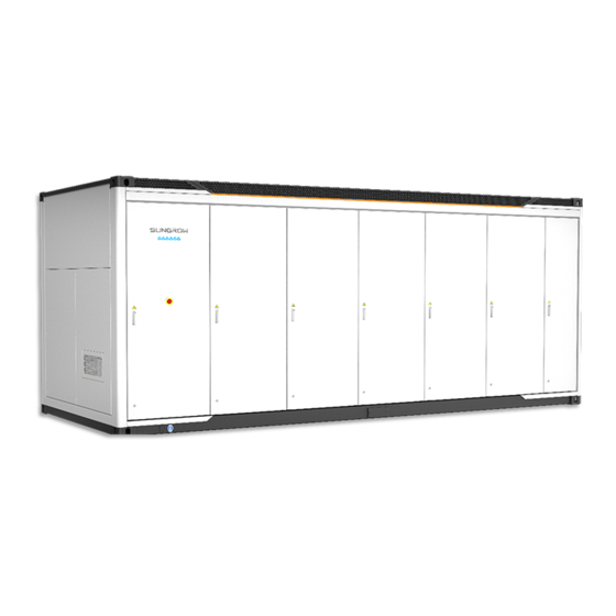
User Manual 2 Product Description figure 2-2 Appearance * The figure is for reference only. The product received may differ. Name LED indicator Emergency stop button Door lock Grounding point Emergency ventilation system The nameplate contains important parameter information related to the battery container, and shall be protected during transportation, installation, maintenance and troubleshooting.
Page 22
2 Product Description User Manual table 2-1 Indicator status Description Status The system works normally Steady on (charge and discharge). 2s periodic slow blinking The system is normal, no char- Blue ging and discharging. (Breathing light) A fault occurs (auxiliary circuit Steady on breaker does not trip).
Page 23
User Manual 2 Product Description The clearance space figure 2-4 The diagram of the required space when the door is opened *The figure is for reference only and the actual product shall prevail! 2.2.3 Ventilation Design The battery container intakes air from the front / top side and expels it from the top, as shown below.
Page 24
2 Product Description User Manual figure 2-6 Internal equipment components * The figure is for reference only. The product received may differ. table 2-2 Internal equipment description Name Battery cluster (Rack) Terminal box (TB) & DC/AC power converter unit Integrated cabin Liquid cooling system (LCS) LCS control box Battery connection panel (BCP)
Page 25
User Manual 2 Product Description * The figure is for reference only. The product received may differ. table 2-3 Panel Description Description DC terminals AC terminals Indicator light Communication plugs Network port Ventilation valve LED Indicator This panel is for users to check the current working status of the SC210HX-US. table 2-4 LED indicator status description Indica- Status description...
Page 26
2 Product Description User Manual * The figure is for reference only. The product received may differ. Parameters table 2-5 SC210HX-US parameters Name Parameter values DC voltage range (rated power) 1000 V ~ 1500 V Max. DC current 212.8 A Rated AC voltage 690 V AC voltage range...
Page 27
User Manual 2 Product Description * The figure is for reference only. The product received may differ. table 2-6 Panel Description Description DC terminals 1500V power supply terminals AC terminals Indicator light Network ports Communication terminals DC Bulkheads AC Bulkheads Communication Bulkheads LED Indicator This panel is for users to check the current working status of the TB.
Page 28
2 Product Description User Manual Status description Indicator Status A fault occurred (The TB shuts down Steady on immediately). Fast blinking Bluetooth is connected and there is data com- (Interval: 0.2s) munication. A fault occurred. The AC and DC sides are disconnected. Dimension The TB form factor is shown in the diagram.
Page 29
User Manual 2 Product Description 2.3.4.1 Cell table 2-8 Cell parameters Cell Parameter Value Size (thickness * (71.65 ± 0.5) mm * (204.44 ± 0.8) shoulder height * mm * (174.26 ± 0.8) mm width) Weight (5.49 ± 0.3) kg Rated capacity 314 Ah Rated energy...
Page 30
1123.2 V ~ 1497.6 V Rated capacity IP rating 628 Ah IP65 The parameter values are for reference only, please refer to the actual project! 2.3.4.4 Battery Cluster Stacking Method table 2-12 Battery cluster stacking method (0.5C) Stacking method Module ST5015UX-2H-US ST4595UX-2H-US ST4175UX-2H-US...
Page 31
User Manual 2 Product Description Stacking method Module ST3760UX-2H-US ST3340UX-2H-US Note: means battery module, means battery cluster, means no equipment, TB means terminal box. table 2-13 Battery cluster stacking method (0.25C) Stacking method Module ST5015UX-4H-US ST4175UX-4H-US ST3340UX-4H-US...
Page 32
2 Product Description User Manual Note: means battery module, means battery cluster, means no equipment, TB means terminal box. The number of battery clusters in the battery cabinet must be equal within the same block.
Page 33
Transport and Storage Precautions Failure to transport and store the product in accordance with the requirements in this manual may invalidate the warranty. Transport Methods The battery container can be transported by road and sea. The battery container is highly in- tegrated and easy to hoist, which facilitates its transport.
Page 34
3 Transport and Storage User Manual In the whole process of loading, unloading, and transportation, the safe operation regulations of battery container in the country/region where the project is located must be observed! • All tools used for the battery container and during operation shall be properly maintained.
Page 35
User Manual 3 Transport and Storage *The figure is for reference only and the actual product shall prevail! Storage Requirements If the battery container will not be used within 3 months, store it according to the storage requirements. Damage resulting from failure to meet the storage require- ments will not be covered by the warranty.
Page 36
3 Transport and Storage User Manual Temperature range Attenuation coefficient 26 ℃ ~ 40 ℃ 0.1 %/month 41 ℃ ~ 50 ℃ 0.3 %/month • Long-term storage of batteries is not recommended because it may cause the decrease in battery capacity. Even if the battery is stored at the recommended storage tempera- ture, irreversible capacity fade will still occur during periods of rest.
Page 37
User Manual 3 Transport and Storage Starting from the date of departure SUNGROW factory, the battery container with a storage period of more than 6 months under the above conditions are to be charged and discharged once to bring the system SOC to 30%~40%.
Page 38
Check the battery container and the internal equipment for any damage. If any problems are found or there is any question, please contact the forwarding company or SUNGROW. Only install the battery container when it is complete and intact. Before installation, ensure that: •...
Page 39
If the requirements cannot be met due to geographical restrictions, use noise mitigation measures. For detailed solutions, consult with the designer or SUNGROW. • Avoid installing the battery container in dusty environments with a large amount of dust, smoke, or floc.
Page 40
4 Mechanical Installation User Manual Given that the installation site has been decided and the foundation has been set up before the arrival of the battery container, details on these two items will not be included in this manual. Unreasonably constructed foundation will bring great troubles to the installation of the bat- tery container, affecting the normal opening and closing of the doors and the normal opera- tion.
Page 41
User Manual 4 Mechanical Installation – To facilitate subsequent electrical wiring, it is recommended to pre-set a cable trench in the foundation according to the position of cable inlet holes of the battery container, and pre-embed the conduit. – The dregs excavated during foundation construction should be removed immediately to avoid latter impact on lifting.
Page 42
4 Mechanical Installation User Manual • Drainage: The accessway should has a good drainage system to prevent slipping caused by water accumulation. Apply anti-slip treatment in slippery areas, such as set- ting anti-slip strips or applying anti-slip paint. 4.2.3 Foundation Construction This section is not for foundation construction purpose, and should only be used as references in the foundation designing process.
Page 43
User Manual 4 Mechanical Installation Description Embedded M16 expansion nuts Pillar foundation Main power circuit AC cable inlet/outlet area Auxiliary power supply AC cable inlet/outlet area Communication cable inlet/outlet area The 30#-c channel dimensions are shown below. figure 4-2 30#-c channel steel dimensions * The figure is for reference only.
Page 44
4 Mechanical Installation User Manual figure 4-4 Foundation design reference plan (top view) * The figure is for reference only. The product received may differ. If the height difference between the highest point and the lowest point of 1~8# foundation is within the range of 0~10mm, then the foundation flatness meets the design requirements, and the equipment can be lifted and fixed with the foundation normally;...
Page 45
User Manual 4 Mechanical Installation 4.2.5 Installation Spacing Requirement The distance marked in this chapter is the minimum distance for operation & maintenance, installation, and heat dissipation. Customers can increase the distance according to the local fire control regulation and add firewall when necessary. •...
Page 46
4 Mechanical Installation User Manual figure 4-8 Installing multiple devices(back-to-back) * The figure is for reference only. The product received may differ. For back-to-back installation, the normal distance range is 150~170 mm and the suggested distance is 150 mm. Please contact our technical engineer if the dis- tance needs to exceed 170 mm.
Page 47
User Manual 4 Mechanical Installation Distance Requirement Between Battery Cabinets and MVS figure 4-9 Suggested layout A (0.5C) * The figure is for reference only. The product received may differ. figure 4-10 Suggested layout B (0.5C) * The figure is for reference only. The product received may differ.
Page 48
4 Mechanical Installation User Manual figure 4-11 Suggested layout C (0.25C) * The figure is for reference only. The product received may differ. figure 4-12 Suggested layout D (0.25C) * The figure is for reference only. The product received may differ.
Page 49
– If the system includes a SUNGROW battery cabinet and a firewall is present on site, ensure that the designated area for the battery cabinet is ≥ 150 mm away from the firewall.
Page 50
Please use the hoisting devices provided by SUNGROW (slings, shackles, and hoisting beams). • If it is necessary to use slings and shackles that are not provided by SUNGROW due to special circumstances, ensure that the selected hoisting devices meet the requirements specified in “Hoisting Schematic”.
Page 51
User Manual 4 Mechanical Installation Safety instructions Perform operations in strict accordance with the local safe operating procedures relevant to the country or region, including but not limited to: • Stop hoisting immediately in severe weather conditions, such as heavy rain, fog, or strong winds.
Page 52
User Manual figure 4-13 Lifting schematic * The figure is for reference only. The product received may differ. Lifting devices The crane comes with a lifting hook. SUNGROW provides the other lifting devices, as listed in the table below. Specification Quantity...
Page 53
Verify that the equipment is free from deformation and that its doors open and close smoothly. After hoisting, properly store the hoisting devices provided by SUNGROW for future use. 4.3.4 Fixed Installation The battery container shall be fixed after being transported to the installation position.
Page 54
4 Mechanical Installation User Manual Top Fixation (Distance between the two battery container is 150 mm ~ 170 mm) figure 4-14 Top fixation diagram * The figure is for reference only. The product received may differ. When connecting with standard connectors, the distance between two cabinet is 150 mm, and the allowable tolerance range is 0 ~ +20 mm.
Page 55
User Manual 4 Mechanical Installation All welding components require to be fully welded, and after the welding is completed, anti- corrosion treatment is applied to the welds. figure 4-15 Full welding schematic * The figure is for reference only. The product received may differ. •...
Page 56
4 Mechanical Installation User Manual Film Removal Before putting the battery container into operation, remove the film. During transportation, the 3M film is applied to the surface of the cabinet in the following locations. figure 4-16 Battery container film placement diagram * The figure is for reference only.
Page 57
Electrical Connection Precautions High voltage! Electric shock! • It is strictly forbidden to directly touch the live parts in the unprotected state! • Make sure that both the AC and DC sides are not energized before installation. • Do not place the unit on a flammable surface. •...
Page 58
5 Electrical Connection User Manual When an external short circuit occurs in the Rack circuit, or when the terminal box fuse generates a protective action, the fuse in the terminal box and the inter-cluster fuse must be replaced, and all manual service disconnect (MSD) need to be replaced.
Page 59
User Manual 5 Electrical Connection Recommended cable Description Bolt hole size specifications Dry contact signal port 250 kcmil~300 kcmil Grounding point yellow and green cable M10 / φ11~13 or grounding flat steel 0.25C System figure 5-2 Wiring diagram (0.25C) *The diagram only describe the on-site wiring, and the internal wiring is for reference only. table 5-2 Interface description 2 Recommended cable Description...
Page 60
Only qualified electricians can perform the electrical connection. Please comply with the requirements in “Safety Precautions” in this manual. SUNGROW shall not be held liable for any personal injury or property damage caused by ignoring these safety precautions.
Page 61
User Manual 5 Electrical Connection Preparation Before Wiring 5.3.1 Preparing Installation Tools Safety gloves Goggles Safety shoes Protective clothing Torque screwdriver Wire stripper Hydraulic pliers Heat gun Torque wrench Screwdriver Multimeter 5.3.2 Open the Door Open the door before the cable is connected。 figure 5-3 Steps of opening the door Step Description...
Page 62
• Select communication cables equipped with corresponding shielding protection features according to the requirements of SUNGROW. • Secure the power cables and the communication cables separately. Ensure a minimum space of 10cm between the lines of strong and weak electricity to avoid electromagnetic...
Page 63
User Manual 5 Electrical Connection • The cables used should comply with requirements of local laws and regulations. • The cable color in figures in this manual is for reference only. Please select cables according to local standards. Crimp terminal Crimp OT/DT terminals Follow the steps shown below to crimp terminal.
Page 64
5 Electrical Connection User Manual figure 5-4 Copper cable terminal connection sequence Name Name Copper bus bar Bolt Copper connection Flat washer terminal Spring washer • When fastening the product and terminals, tighten the fasteners at the specified torques using proper tools and leave marks accordingly. Otherwise, the product may be damaged, and such damages will not be covered by the warranty.
Page 65
*The above inlet hole dimensions are the maximum specifications for the opening. If you need to pre-bury the wire pipe in the inlet area during construction, please contact SUNGROW for confirmation of the specific location. After wiring is completed, be sure to use fireproof/waterproof materials such as...
Page 66
5 Electrical Connection User Manual The product must be double grounded, with both grounding points reliably grounded. Ground the product strictly following local standards and regulations. • Before grounding, it is necessary to clean the periphery of the threaded port of the grounding point and the surface of the grounding point to a clean state, so as not to have an impact on the grounding performance.
Page 67
During the grounding connection process, please contact the relevant staff if you have any questions. Failure to follow the installation specifications, or pri- vate installation or modification may lead to safety accidents or equipment da- mage. SUNGROW is not liable for any damages caused by this.
Page 68
5 Electrical Connection User Manual Primary Circuit Connection Before connecting the DC input cables, check the cable insulation according to the local regulations. 5.5.1 Main Power Supply Connection (0.5C) Overview The main power supply terminals are connected from the BCP side to the smart control cabi- net (SCC) side, the location of the terminals is shown in the figure below.
Page 69
User Manual 5 Electrical Connection Step 1 Lead the cable into the wiring area through the inlet hole, and mark the cable phase. Step 2 Strip the protective layer of the cable to expose the copper core of the wire with strippers. Step 3 Crimp with DT terminal, refer to"5.3.3 Prepare Cables".
Page 70
5 Electrical Connection User Manual Battery Recommended Description contain- Mark specification BCP-AC-A3/B3/ BCP-AC-A1/B1/ 2# battery BCP-AC-A2/B2/ Connected to SCC-QF1-A1/B1/ 750 kcmil container BCP-AC-A3/B3/ BCP-AC-A1/B1/ 3# battery BCP-AC-A2/B2/ Connected to SCC-QF2-A2/B2/ 750 kcmil container BCP-AC-A3/B3/ BCP-AC-A1/B1/ 4# battery BCP-AC-A2/B2/ Connected to SCC-QF2-A2/B2/ 750 kcmil container BCP-AC-A3/B3/...
Page 71
User Manual 5 Electrical Connection Secondary Circuit Connection Before connecting the AC output cables, check the cable insulation according to the local regulations. 5.6.1 Auxiliary Power Supply Connection (0.5C) The SCC supplies power to the LCS, 24Vdc devices, fans, and other devices in the battery container through an auxiliary external power supply.
Page 72
5 Electrical Connection User Manual Step 3 Crimp with DT terminal, refer to"5.3.3 Prepare Cables". Step 4 Secure the DT terminal to the wiring hole by M8 bolt with a tightening torque of 18~23 N·m. (For detailed wiring procedure, please refer to "5.3.4 Copper Wire Connection".
Page 73
User Manual 5 Electrical Connection figure 5-11 Auxiliary power supply terminals diagram (0.25C) * The image shown here is for reference only. The actual product received may differ. table 5-6 Interface description (0.25C) Bat- Recommended tery Description Mark specification con- tainer 1# bat- BCP-QF1-L1...
Page 74
5 Electrical Connection User Manual Step 5 Pull the cable back slightly after wiring to ensure that the cable is long enough. figure 5-12 Diagram of terminal phase sequence * The image shown here is for reference only. The actual product received may differ. •...
Page 75
User Manual 5 Electrical Connection Battery Recommended Description contain- Mark specification Q8-2 Connected to SCC-Q7-2 1# battery 15 AWG container Q8-4 Connected to SCC-Q7-4 Q8-2 Connected to SCC-Q8-2 2# battery 15 AWG container Q8-4 Connected to SCC-Q8-4 Q8-2 Connected to SCC-Q9-2 3# battery 15 AWG Q8-4...
Page 77
User Manual 5 Electrical Connection Description Recommended specification Mark XX2-5 FSS Level 2 Alarm XX2-6 FSS Level 2 Alarm *The noted cable specifications are recommended values. It can be adjusted according to actual needs. Step 4 Wiring according to the port identification and definition. Tighten with a screwdriver with a tor- que of 0.7±0.1 N·m.
Page 78
The safety precautions in this manual do not cover all specifications to be fol- lowed, and all operations should be performed based on the site conditions. • SUNGROW shall not be liable for any loss arising from failure to follow the safety precautions in the manual. •...
Page 79
User Manual 6 Battery Connection • All connections must be carried out with distinctive guidance. Any guess and ambiguous attempts must be prohibited. • Key connections must be correct, reliable (without loosening) and in good contact, with- out short-circuits. • All the finished connections must be measured and confirmed one by one.
Page 80
6 Battery Connection User Manual Step 3 Install the fuse. Open the cabinet door, there are 12 sets of mounting holes reserved on the door frames of the cabinet, and use M6 hexagonal Phillips screws to fix the fuses on the mounting holes.
Page 81
User Manual 6 Battery Connection Step 4 Correctly insert the aviation plug that comes with the fuse into the battery base. figure 6-4 Insert the fuse into the battery base When the aviation plug is plugged tightly, it will make a "click" sound. Make sure the aviation plug is plugged in tightly! •...
Page 82
6 Battery Connection User Manual Step 6 Connecting the power cables between packs, illustrated by Rack1#. And you will hear a click- ing sound after the air plug is plugged in tightly. (Skip this step if the power cable between the Packs is connected) Connecting BAT+ of R1-1 to BAT- of R1-2.
Page 83
User Manual 6 Battery Connection Step 7 Connecting the power cables between the packs and TB, illustrated by Rack1~2#. (Skip this step if the power cable between the Pack and the TB is already connected) Connecting BAT- of R1-1 to DC1- of TB1#. Connecting BAT+ of R1-4 to DC1+ of TB1#.
Page 84
6 Battery Connection User Manual Install MSD The MSD is fused to protect against short circuit conditions outside the Pack. • The MSD installation on each Pack needs to be completed before power-on, and the MSD on each Rack is installed in the order of Pack1~Pack4. •...
Page 85
Powering up and Shutdown Power-on Operation The battery container can only be put into operation after confirmation by a profes- sional and approved by the local power department. For the battery container that has a downtime of over two months, before starting- up, check that the system communication is normal, the battery voltage is in the normal operating range, and the components can function properly.
Page 86
7 Powering up and Shutdown User Manual • All Packs have completed MSD insertion as required. Step 1 Power on the MVS. Step 2 Power on the auxiliary power supply. Close the main control switch of the 480Vac power QF1 (AC MAIN SWITCH); Close the power switch of the LCS Q1 (LCS);...
Page 87
User Manual 7 Powering up and Shutdown Prepare for shut down: the software control system shuts down and disconnects the battery relay (special case shutdown can be done by pressing the cabinet emergency stop button). Use the emergency stop button only in case of a fault in the equipment or an emer- gency.
Page 88
Do not lose the MSD after pulling it out, and store it properly to avoid dropping and moisture. - - End 7.2.3 Unplanned (Emergency) Shutdown • Fire incident: Contact local fire department professionals. • Unplanned outage (shutdown due to faults): Contact SUNGROW.
Page 89
Fire Suppression General Rules Please comply with the fire laws and regulations of the country/region where the project is located. Perform regular inspection and maintenance on the fire suppression system regularly to en- sure it can function properly. When the operations manager receives an alarm or fault signal from a locker in the software or the station-level FACP, a firefighting professional is required to manu- ally reset the locker on-site after on-site troubleshooting to ensure safety.
Page 90
8 Fire Suppression User Manual Fire Suppression Equipment The battery container is equipped with an automatic fire alarm and linkage control system, an explosion relief system, a combustible gas detection and alarm system and an exhaust system (optional), a water-based fire suppression system (optional). It is equipped with com- bustible gas detectors (optional), smoke detectors, and temperature detectors.
Page 91
User Manual 8 Fire Suppression Vent panel The battery container is equipped with Vent panel for pressure relief and feedback the status signal of the relief plate. Six explosion relief plates are located on the top of the cabinet and evenly distributed.
Page 92
8 Fire Suppression User Manual When the smoke and temperature detectors act at the same time, it will be judged as a level 2 alarm and the signal will be fed back to BSC. BSC transmits the alarm signal/ feedback signal to LC, which receives the level 2 alarm and controls the whole block sys- tem shutdown.
Page 93
User Manual 8 Fire Suppression Customers using automatic sprinkler systems must be external piping, external piping by the customer's own design. figure 8-4 Piping of water-based fire suppression system * The image shown here is for reference only. The actual product received may differ.
Page 94
Troubleshooting Overview When an abnormal change occurs in the battery container, it is recommended that prelimin- ary troubleshooting be performed first through the troubleshooting and troubleshooting methods described in the LC300 interface. The LC300 controller is located in the MVS-SCC. figure 9-1 LC location * The figure is for reference only.
Page 95
Step 4 Choose the system type, enter the username and password, and click Login. In the system, there are two types of users: operator and admin. The login password is dynamic, please contact SUNGROW to get it. Step 5 Select the desired language on the upper righter corner of the interface.
Page 96
9 Troubleshooting User Manual Type Troubleshooting advice Name Reason Abnormal communi- cation between all DC/AC power con- verter units and LC • Check whether the DC/AC power converter unit is normally started. under the system. • Check the communication lines •...
Page 97
User Manual 9 Troubleshooting Type Troubleshooting advice Name Reason • Check that the system's lower LC and upper network are on a local There is a malfunc- area network. tion in the communi- Host compu- • Check the communication lines cation between LC ter comm between the system's lower LC...
Page 98
9 Troubleshooting User Manual Type Troubleshooting advice Name Reason During system op- eration, continuously check whether the power of the DC/AC power converter unit Manually click the power line check Power line and the battery unit button, the fault is restored after the abnormal is the same, if the check is passed.
Page 99
User Manual 9 Troubleshooting Type Troubleshooting advice Name Reason Check whether there is alarm infor- DC/AC Alarms of one or mation in DC/AC power converter power con- more DC/AC power units, and take targeted measures ac- verter unit converter units. cording to the DC/AC power conver- alarm ter unit manual to clear the alarm.
Page 100
9 Troubleshooting User Manual Type Troubleshooting advice Name Reason Communication ab- normality of one or more BSC of the sys- • Check whether the 24V auxiliary power of the battery container is tem with LC. normal, and check whether the LC •...
Page 101
User Manual 9 Troubleshooting Type Troubleshooting advice Name Reason • Check whether the SOC value SOC level-1 lower corresponding to BSC is lower than level-1 lower limit. limit protection is trig- SOC lower gered for one or • Charge the battery to lift SOC or limit 1 alarm more BSC of the stop discharging.
Page 102
9 Troubleshooting User Manual Type Troubleshooting advice Name Reason There is a communi- • Check the auxiliary power supply. Breathing cation failure be- • Check that the controller is con- light comm tween the LC and nected to the breathing light com- alarm the breathing light munication cable.
Page 103
*If the fault is not cleared after the operation above, please contact SUNGROW. • Follow strictly the instructions specified by the warning signs when performing maintenance. • After completing DC-side maintenance, such as PACK/DC/AC power converter...
Page 104
“Total under voltage alarm”. End users must assign a high priority to above listed faults and alarms reported by the Sungrow local controller. When an alarm or fault is triggered, the user interface should prominently highlight these issues. Furthermore, end users should promptly contact Sungrow for timely resolution to prevent battery warranty loss due to over-discharge or overcharge.
Page 105
User Manual 10 SOC Calibration Instructions • If the system will not be in operation for an extended period (7 days or more), it's recommended to increase the SOC lower limit protection value to above 10% SOC. Additionally, it is important to regularly monitor the system's SOC to avoid the risk of over discharge which will cause warranty expiration.
Page 106
11 Passive Balancing Passive balancing generally discharges the cells with higher voltage in the battery cluster by means of resistance discharge, releasing power in the form of heat to achieve the purpose of overall cell balancing. Passive balancing does not need to be set manually and can be turned on automatically. Passive balancing triggered conditions •...
Page 107
User Manual 11 Passive Balancing • No impact to normal operation even if passive balancing is paused because of SOC low- er than 5%. Because once the SOC higher than 5%, the process will be continuous again automatically without extra command, until close condition is triggered. •...
Page 108
12 Routine Maintenance 12.1 Precautions Before Maintenance • During daily operation, the doors of the battery container and its internal de- vices must all be closed and locked. Besides, the keys should be pulled out and handed over to the designated personnel for safekeeping. This prevents acci- dents caused by unauthorized entries and protects the internal devices against rainwater or damages by animals.
Page 109
To avoid electric shock, do not perform any other maintenance operations be- yond this manual. • If necessary, contact SUNGROW customer service for maintenance. Power failure inspection requirements: • Put up highly visible warning signages near the switches that have been switched off, to prevent accidental switching-on.
Page 110
12 Routine Maintenance User Manual In the event of heavy snowfall at the project site, please clear the snow from the top of the equipment and the surrounding area in a timely manner. In fair weather, it is recommended to open the container door to dehumidify the equipment.
Page 111
User Manual 12 Routine Maintenance 12.2.2 Maintenance (Every half a year) Item Check method System condi- • Clean the foundation (use a broom/vacuum cleaner). tions and • Check if there is dust or dirt on the outdoor cabinet inlet filter cleanliness screen, and clean it if necessary.
Page 112
12 Routine Maintenance User Manual Item Check method • Check to see if the compressor sounds normal when running, and if there are any abnormal vibrations or noises. • Check if the dirty and blocked area of the heat emission & air inlet hole of the water pump is above 5%.
Page 113
User Manual 12 Routine Maintenance 12.2.3 Maintenance (Once a year) Item Check method • Check if there are any flammable objects around and on top of the outdoor cabinet. • Check if the welds between the outdoor cabinet and the founda- tion steel plate are secure and free from rust.
Page 114
12 Routine Maintenance User Manual Item Check method Check if the lightning protection devices and fuses are intact and op- Components erational. Replace damaged lightning protection devices and fuses in time. • Visually inspect the detectors inside the outdoor cabinet. Check the appearance of the equipment for any damage or deformation, and ensure that it is not being squeezed by surrounding equip- ment.
Page 115
User Manual 12 Routine Maintenance 12.3 Container Maintenance 12.3.1 Painting Make-up Measures Check the exterior damage and choose the applicable program based on the different levels of damage. Case 1:Dirt on surface caused by water spots and dusts can be cleaned. Case 2:Surface dirt and damaged finish, which cannot be cleaned.
Page 116
12 Routine Maintenance User Manual Perform paint repair for the scratched parts with a soft brush after the surface is dried, brush the paint as uniform as possible. Maintenance Steps for Case 3: Material: Name Source Abrasive paper Cleaning cloth Water Not included in the scope of supply Alcohol...
Page 117
“Total under voltage alarm”. End users must assign a high priority to above listed faults and alarms reported by the Sungrow local controller. When an alarm or fault is triggered, the user interface should prominently highlight these issues. Furthermore, end users should promptly contact Sungrow for timely resolution to prevent battery warranty loss due to over-discharge or overcharge.
Page 118
In order to avoid triggering the warranty expiration condition, when the “Cell Under-voltage Fault” or “Cell Over-voltage Fault” is triggered, the user must contact the local team of Sungrow within 24 hours and follow the requirements of Sungrow to carry out the next operation.
Page 119
User Manual 12 Routine Maintenance Maintenance performed once two years Inspection item Inspection method Check the following items. In case of nonconformity, take corrective actions immediately: • Check the battery cluster and internal devices for da- mage or deformation. • Check the internal devices for abnormal noise during Battery cluster status and operation.
Page 120
12 Routine Maintenance User Manual Maintenance performed once a year Inspection item Inspection method Check the following items. In case of nonconformity, take corrective actions immediately: • Check whether there are flammable objects at the top of the battery cluster. •...
Page 121
In case of any doubt on operation and maintenance of this product, contact the Custo- mer Service Center of SUNGROW instead of operation without permission. 12.4.3 Maintenance PACK operating temperature: The working temperature should be kept between -30℃–...
Page 122
12 Routine Maintenance User Manual The RACK should not be charged or discharged with high magnifying power. The contin- uous charging and discharging current of a single rack should not exceed the rated current. When the energy storage system is not used in a long time, it should be charged once every six months, until its SOC is 30%–40%.
Page 123
User Manual 12 Routine Maintenance 12.5 Maintenance of Liquid Cooling System Semi-annual maintenance checks are recommended for liquid cooling system. The actual maintenance period shall be adjusted reasonably in consideration of the specific installation environment of the product. Factors like the power plant scale, the location, and the site environment can affect the maintenance period of the product.
Page 124
12 Routine Maintenance User Manual Mainte- Item Content Check method nance tools • The fan blade rotates smoothly without ab- normal noise. Check whether the fan blades Screwdriver • No damage to fan cannot rotate or are damaged. If with long blade.
Page 125
1. There are obvious slotted screwdriver impurities in antifreeze; 5–6 years Coolant Note: Please contact Sungrow Cus- 2. Antifreeze is signifi- tomer Service to replace hardware cantly darker in color. facilities Normally coolant is not a health hazard, excessive exposure may cause irritation to the eyes, skin and breathing.
Page 126
12 Routine Maintenance User Manual Protective parts Protective equipment Eyes protection Please use protective goggles. Skin and body Use non-permeable protective clothing and safety shoes. protection Disposal considerations Waste types Disposal measures Discharges are made in accordance with local regulations and Coolant are not disposed of haphazardly.
Page 127
User Manual 12 Routine Maintenance Contact method Measures Flush eyes with plenty of water for at least 15 minutes. Seek medical Eyes contact attention. If ingested, but conscious, water or milk to drink and actively seek medical help, do not induce vomiting unless instructed by healthcare Ingestion patients.
Page 128
12 Routine Maintenance User Manual 12.7.1 Automatic Fire Alarm System System check table 12-1 Objects, items and quantities of monthly and quarterly system inspections Inspection Inspection items Inspection frequency objects It should be ensured that each detec- tor is checked for fire alarm function Fire detectors Fire alarm function at least once a year.
Page 129
User Manual 12 Routine Maintenance • Smoke detector Clean the sensing components and circuit boards with specialized process equipment and calibrate the detector response thresholds after cleaning. • Temperature detector Clean temperature-sensitive parts and circuit boards with specialized process equipment, and calibrate the detector response time after cleaning.
Page 130
12 Routine Maintenance User Manual • Do not leave screws, washers, or other metal parts inside the cabinet during mainte- nance. Otherwise, the equipment may be damaged. • Make sure all screws are tightened in place. • In most cases, the protective covers inside the equipment need to be removed before the maintenance work.
Page 131
13 Appendix 13.1 System Parameters Product Name ST5015UX-2H-US ST5015UX-4H-US DC side Cell Type Battery 416S12P Configuration Nominal Capacity 5015 kWh Nominal Voltage 1123.2 V ~ 1497.6 V Range AC side Nominal AC power 210 kVA * 12 210 kVA * 6 AC Current Distor- <...
Page 132
13 Appendix User Manual Product Name ST5015UX-2H-US ST5015UX-4H-US Degree of Type 3S Protection Anti-corrosion Degree Operation Humid- 0 ~ 100 % (Non-condensing) ity Range Operation Ambient -30℃ ~ 50℃ (> 45℃ De-rating) Temperature -22℉ ~ 122℉ ( > 113℉ De-rating)
Page 133
User Manual 13 Appendix Complete designation Abbreviations Fire Suppression System FACP Fire Host Alarm Control Panel Heating, Ventilating and Air Conditioning HVAC Liquid Cooling System Local Controller Lithium Iron Phosphate Lower Explosive Limit Medium Voltage Substation Manual Service Disconnect Personal Computer Personal Protective Equipment Smart Control Cabinet Switching Mode Power Supply...
Page 134
• The customer shall give SUNGROW a reasonable period to repair the faulty device. Exclusion of Liability In the following circumstances, SUNGROW has the right to refuse to honor the quality guarantee: • The free warranty period for the whole machine/components has expired.
Page 135
User Manual 13 Appendix 13.5 Contact Information In case of questions about this product, please contact us. We need the following information to provide you the best assistance: • Model of the device • Serial number of the device • Fault code/name •...
Page 136
Sungrow Power Supply Co., Ltd. www.sungrowpower.com...
Need help?
Do you have a question about the ST5015UX-2H-US and is the answer not in the manual?
Questions and answers