
Related Manuals for Sungrow SBR096


Summary of Contents for Sungrow SBR096
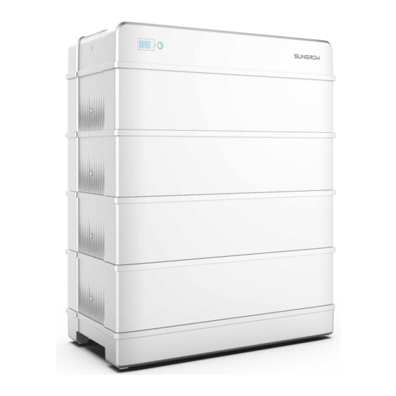
- Page 1 High Voltage LFP Battery User Manual SBR096 / SBR128 / SBR160 SBR192 / SBR224 / SBR256 WWW.SUNGROWPOWER.COM SBR096-256-UEN-Ver11-202012...
-
Page 3: All Rights Reserved
It is prohibited to use data contained in firmware or software developed by • SUNGROW, in part or in full, for commercial purposes by any means. It is prohibited to perform reverse engineering, cracking, or any other operations that •... -
Page 4: About This Manual
. . s s u u n n g g r r o o w w p p o o w w e e r r . . c c o o m m or on the webpage of the respective component manufacturer. V V a a l l i i d d i i t t y y This manual is valid for the following battery models: SBR096 • SBR128 • SBR160 •... - Page 5 Indicates a hazard with a high level of risk that, if not avoided, will result in death or serious injury. Indicates a hazard with a medium level of risk that, if not avoided, could result in death or serious injury. Indicates a hazard with a low level of risk that, if not avoided, could result in minor or moderate injury.
-
Page 7: Table Of Contents
C C o o n n t t e e n n t t s s All Rights Reserved .....................I About This Manual .....................II 1 Safety ......................1 1.1 Notices for Safe Use ..................1 1.2 Battery Handling Information ................ 2 1.3 Emergency Situations .................. - Page 8 5.5 Installing the SUNCLIX Connector............... 25 5.6 Installing the COMM IN Connector.............. 27 6 Commissioning ................... 30 6.1 Inspection before Commissioning............... 30 6.2 Commissioning Procedure ................. 30 7 Decommissioning the Battery ............... 31 8 Troubleshooting and Maintenance ............32 8.1 Troubleshooting ..................32 8.2 Maintenance ....................
-
Page 9: Safety
The safety instructions in this manual cannot cover all the precautions that should be followed. Perform operations considering actual onsite conditions. SUNGROW shall not be held liable for any damage caused by violation of the safety instructions in this manual. -
Page 10: Battery Handling Information
1 Safety User Manual Risk of fire Do not expose the battery to temperatures in excess of 60°C. • Do not place the battery near a heat source, such as direct sunlight, a • fireplace, a thermally uninsulated wall exposed to sunlight, hot water, or a heater. -
Page 11: Emergency Situations
User Manual 1 Safety Do not repair or modify the battery. It is not user serviceable. • Do not pull out any cables when the battery is powered on. • Do not damage the sheath of cables, wire harness and connectors. •... -
Page 12: Wet Batteries
If the battery is submerged in water, do not let people access it, and then contact Sungrow or an authorized service partner for technical support. If a battery is submerged in water or flooded, first, switch off all circuit breakers in the system to cut off the power supply to the battery. - Page 13 Pack it in its original container. Store it in a separated room like the installation place. Contact SUNGROW. A damaged battery may release dangerous material and a flammable gas mixture. Never try to repair the battery even if you are qualified electrician.
-
Page 14: Product Description
Product Description 2.1 Product Introduction B B r r i i e e f f I I n n t t r r o o d d u u c c t t i i o o n n The battery is designed for residential energy storage systems. The inbuilt battery management system monitors its operation and prevents the battery from operating beyond the specified limitations. - Page 15 LED indicator indicates the SOC value and status of the battery. Nameplate The nameplate clearly indentifies the product. The nameplate must remain permanently attached to the product. You will find the following information on the nameplate: SUNGROW logo and product model • Technical data • Product symbol •...
-
Page 16: Terminal Description
S S i i d d e e c c o o v v e e r r g g e e a a r r m m o o d d u u l l e e SBR096 SBR128 SBR160... -
Page 17: Symbols On The Product
User Manual 2 Product Description D D e e s s c c r r i i p p t t i i o o n n N N o o . . L L a a b b e e l l To enable the communication between the inverter •... -
Page 18: Led Indicator
2 Product Description User Manual S S y y m m b b l l o o E E x x p p l l a a n n a a t t i i o o n n Do not dispose in trash. Compacting a lithium ion battery is dangerous as it can explode. -
Page 19: Unpacking And Storage
Check the inner contents for damage after unpacking. • Contact SUNGROW or the supplier in case of any damage or incompleteness. Do not dispose of the original packing case. It is recommended to store the device in it. 3.2 Scope of Delivery... -
Page 20: Storage
3 Unpacking and Storage User Manual Q Q u u a a n n t t i i t t y y I I t t e e m m N N a a m m e e M5 screw 8 ~ 18 Expansion plug set M5 screw sets... -
Page 21: Mounting
Mounting 4.1 Safety during Mounting This product or system must be operated by professionals! Failure to follow the safety instructions in this manual or operation of this product or system by non-professionals may cause severe personal injury or major property damage. Strictly follow local relevant standards and requirements in the whole process of installation. -
Page 22: Installation Tools
4 Mounting User Manual In case of multiple batteries, reserve specific clearance between the batteries. • 4.5 Installation Tools Installation tools include but are not limited to the following recommended ones. If necessary, use other auxiliary tools on site. Table 4-1 Tool specification Goggles Dust mask Protective gloves... -
Page 23: Installing The Battery
F F i i g g u u r r e e 4 4 - - 1 1 Layout of holes with the base as reference You can choose not to mount SBR096/128 on the wall. Step 2 Drill the holes according to the marked positions, and install the expansion sleeves. - Page 24 4 Mounting User Manual Step 3 (Optional) Install the feet of the battery. Step 4 Position the base maintaining the required distance from the wall. Step 5 Place each battery module on top of the base.
- Page 25 User Manual 4 Mounting When carrying the battery module, always be aware of its weight of 33 kg. Step 6 Fix the battery modules with the included screws. Step 7 Connect the switch gear to the base.
- Page 26 4 Mounting User Manual Step 8 Fix the switch gear with the provided stud. When 4 or more than 4 battery modules are installed in one base, M5 screw set is required to secure the switch gear. The stud is mounted on the top of battery module.
- Page 27 User Manual 4 Mounting The bracket is mounted on the top battery module. Step 10Connect the harness. For communication between the battery and the inverter. Connect the communication cable from the “COMM” terminal of the battery to the inverter. Strip the insulation layer of the communication cable with a wire stripper, and lead the corresponding CAN1_H/CAN1_L signal cable out.
- Page 28 4 Mounting User Manual Step 11Place the top cover and fix it with the screw provided. Step 12(Optional) Install the side covers. When 4 or more than 4 battery modules are installed in one base, side covers are required. - - - - E E n n d d...
-
Page 29: Parallel System(Optional
Parallel System(Optional) The battery can be expanded to 4 units in parallel at most. Available in Q3, 2021. 5.1 Scope of Delivery Q Q u u a a n n t t i i t t y y I I t t e e m m N N a a m m e e Junction box Bracket... -
Page 30: Terminal Description (Junction Box)
User Manual 5 Parallel System(Optional) - - - - E E n n d d 5.3 Terminal Description (Junction Box) All electrical terminals are located at the bottom of the junction box. F F i i g g u u r r e e 5 5 - - 1 1 Terminals at the Bottom of the Junction Box * The image shown here is for reference only. -
Page 31: Connection Diagram In Parallel System
User Manual 5 Parallel System(Optional) D D e e s s c c r r i i p p t t i i o o n n N N o o . . L L a a b b e e l l Connected to the ground PCS+ terminal, connected to the inverter positive terminal PCS+, PCS-... - Page 32 User Manual 5 Parallel System(Optional) The COMM terminal of the battery is connected to the COMM IN terminal of the • junction box.Signal cable 1 white and orange cable is used as BMS/CAN_H1; signal cable 2 orange cable is used as BMS/CAN_L1; signal cable 5 white and blue cable is used as BMS/CAN_H2;...
-
Page 33: Installing The Sunclix Connector
User Manual 5 Parallel System(Optional) 5.5 Installing the SUNCLIX Connector This section mainly describes the cable connections on the junction box side. For the cable connections on the battery side, refer to the section "Installing the battery". During assembly, be careful not to contaminate, pull out, or shift, the seal in the cable gland. - Page 34 User Manual 5 Parallel System(Optional) Step 3 Insert the stripped cable into the cable gland up to the stop. The stranded wire can be seen inside the spring. Press the spring down until it audibly snaps into place. Step 4 Push the insert into the sleeve and tighten the cable gland (torque 2 N·m). Step 5 Remove the waterproof lid from B B A A T T 3 3 + + and B B A A T T 3 3 –...
-
Page 35: Installing The Comm In Connector
User Manual 5 Parallel System(Optional) Step 7 Ensure that the connectors are securely in place. - - - - E E n n d d 5.6 Installing the COMM IN Connector This section mainly describes the cable connections on the junction box side. For the cable connections on the battery side, refer to the section "Installing the battery". - Page 36 User Manual 5 Parallel System(Optional) Step 4 Remove the cable jacket by 7 mm to 10 mm from the cable that is led out from the battery. Step 5 Plug the wires into the corresponding terminal according the labels on the bottom of the device.
- Page 37 User Manual 5 Parallel System(Optional) Step 9 Remove the waterproof lid from the C C O O M M M M I I N N terminal. Step 10Insert the COMM IN connector into C C O O M M M M I I N N terminal on the bottom of the junction box until there is an audible click.
-
Page 38: Commissioning
Execute step 2, check whether there is a fault in the battery (the indicator light is red), and obtain fault information through iSolarCloud to contact SUNGROW to repair the battery system. -
Page 39: Decommissioning The Battery
Step 2 One minute after the DC breaker is disconnected, disconnect all cables between the battery and other devices. - - - - E E n n d d Contact SUNGROW to dispose of the battery. -
Page 40: Troubleshooting And Maintenance
4. Check whether the fan is running properly. too high. Replace the fan if it is not working properly. 5. Contact SUNGROW if the preceding causes are ruled out and the fault persists. It is detected Shut down and disconnect the lithium-ion that the battery system. - Page 41 2. Check whether the power cable of the system is properly connected. 3. Contact SUNGROW if the preceding causes are ruled out and the fault persists.
- Page 42 If yes, the power n terminal of indicator should be on in blue. the battery or 4. Contact SUNGROW if the preceding causes the inverter is are ruled out and the fault persists. in poor contact. Generally, if the battery system is faulty, the...
- Page 43 2. If the fault causes tripping of the external protection circuit breaker and such tripping occurs for the first time, connect the circuit breaker. 3. If the fault persists, contact SUNGROW. Generally, if the battery system is faulty, the The alarm is battery management system will actively...
-
Page 44: Maintenance
8 Troubleshooting and Maintenance User Manual 8.2 Maintenance Below is the recommended maintenance cycle. The actual maintenance cycle should be adjusted according to the specific installation environment of this product. The power station scale, installation location and on-site environment affect the maintenance cycle of this product. - Page 45 Check whether the current, voltage and temperature in Function inspection the operation record of the battery module are within the operating ranges. Note: The battery has the function of automatic capacity calibration, which is supported only by the Sungrow PCS system.
-
Page 46: Appendix
Appendix 9.1 Technical Data P P a a r r a a m m e e t t e e r r s s S S B B R R 0 0 9 9 6 6 S S B B R R 1 1 2 2 8 8 S S B B R R 1 1 6 6 0 0 S S y y s s t t e e m m D D a a t t a a Battery Type... - Page 47 User Manual 9 Appendix P P a a r r a a m m e e t t e e r r s s S S B B R R 0 0 9 9 6 6 S S B B R R 1 1 2 2 8 8 S S B B R R 1 1 6 6 0 0 Weight 114 kg...
-
Page 48: Quality Assurance
C C o o n n d d i i t t i i o o n n s s After replacement, unqualified products shall be processed by SUNGROW. • The customer shall give SUNGROW a reasonable period to repair the faulty device. •... -
Page 49: Contact Information
E E x x c c l l u u s s i i o o n n o o f f L L i i a a b b i i l l i i t t y y In the following circumstances, SUNGROW has the right to refuse to honor the quality guarantee: The free warranty period for the whole machine/components has expired. - Page 50 M M a a l l a a y y s s i i a a P P h h i i l l i i p p p p i i n n e e s s Sungrow SEA Sungrow Power Supply Co., Ltd Selangor Darul Ehsan Mandaluyong City...
- Page 51 L L u u x x e e m m b b o o u u r r g g ( ( B B e e n n e e l l u u s s ) ) Sungrow Vietnam...
Need help?
Do you have a question about the SBR096 and is the answer not in the manual?
Questions and answers