
Related Manuals for Sungrow SBR064


Summary of Contents for Sungrow SBR064
- Page 1 User Manual High Voltage LFP Battery SBR064/096/128/160/192/224/256 SBR064/096/ 128/160/192/224/256High Voltage LFP BatteryUser ManualSBR064- 256-UEN-Ver19-202302 SBR064-256-UEN-Ver19-202302...
-
Page 3: All Rights Reserved
Software Licenses • It is prohibited to use data contained in firmware or software developed by SUNGROW, in part or in full, for commercial purposes by any means. • It is prohibited to perform reverse engineering, cracking, or any other operations that... -
Page 4: About This Manual
The reader can get additional information about other devices www.sungrowpower.com or on the webpage of the respective component manufacturer. Validity This manual is valid for the following battery models: • SBR064 • SBR096 • SBR128 •... - Page 5 Indicates a hazard with a high level of risk that, if not avoided, will result in death or serious injury. Indicates a hazard with a medium level of risk that, if not avoided, could result in death or serious injury. Indicates a hazard with a low level of risk that, if not avoided, could result in minor or moderate injury.
-
Page 7: Table Of Contents
Contents All Rights Reserved .....................I About This Manual......................II 1 Safety Instructions ....................1 1.1 Notices for Safe Use ..................2 1.2 Battery Handling Information ................2 1.3 Emergency Situations ..................3 1.3.1 Leaking Batteries ..................3 1.3.2 Fire ......................4 1.3.3 Wet Batteries ..................5 1.3.4 Damaged Batteries ................5 2 Product Description ..................6 2.1 Product Introduction..................6... - Page 8 5.2 Commissioning Procedure ................28 6 Decommissioning the Battery ...............31 7 Battery Augmentation ..................32 8 Troubleshooting and Maintenance ..............33 8.1 Troubleshooting ...................33 8.2 Maintenance ....................39 9 Appendix ......................41 9.1 Technical Data .....................41 9.2 FAQs ......................43 9.2.1 Battery Not Charging ................43 9.2.2 Battery Not Discharging...............44 9.2.3 SOC Jump..................44 9.2.4 Battery Upgrade..................44 9.3 Quality Assurance ..................44...
-
Page 9: Safety Instructions
Perform operations considering ac- tual onsite conditions. • SUNGROW shall not be held liable for any damage caused by violation of gen- eral safety operation requirements, general safety standards, or any safety in- struction in this manual. -
Page 10: Notices For Safe Use
1 Safety Instructions User Manual Notices for Safe Use Read all safety instructions carefully prior to any work and observe them at all times when working on or with the battery. Failure to observe the precautions described in this section can cause serious injury to persons or damage to property. -
Page 11: Emergency Situations
User Manual 1 Safety Instructions Any man-made damage will void the limited warranty for the battery. Handle the battery with care to protect it from damage. • Use the battery only as intended and designed. • The battery must only be installed at a suitable location. •... -
Page 12: Fire
1 Safety Instructions User Manual • Ingestion: Induce vomiting, and seek medical aid immediately. Wipe out the contacted area with a sponge or cloth that is soaked in water until you obtain medical aid. These materials can damage skin and eyes, causing blindness. 1.3.2 Fire Fire may occur with the battery despite its careful design. -
Page 13: Wet Batteries
1 Safety Instructions 1.3.3 Wet Batteries If the battery is submerged in water, do not let people access it, and then contact Sungrow or an authorized service partner for technical support. If a battery is submerged in water or flooded, first, switch off all circuit breakers in the system to cut off the power supply to the battery. -
Page 14: Product Description
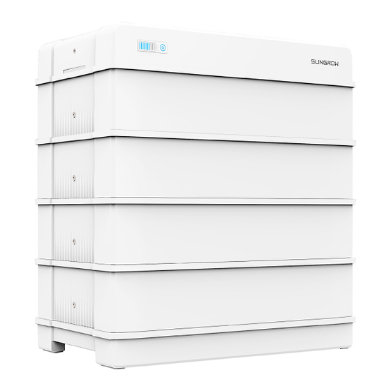
Max.4 battery systems can be connected in parallel to compatible hybrid inverter. Please re- fer to hybrid inverter manual for the compatibility details. figure 2-1 Product overview SBR064 is only applicable to SH3.0-6.0RS. Images are for reference only. The actual products received may differ. - Page 15 Nameplate The nameplate clearly indentifies the product. The nameplate must remain permanently attached to the product. You will find the following information on the nameplate: • SUNGROW logo and product model • Technical data • Product symbol DC circuit breaker Major Components Images are for reference only.
-
Page 16: Terminal Description
Battery module: Single module is 3.2 kWh and used in SBR064-256 battery system. *Empty module: 1. Decorative accessory, which makes the battery height higher, and on the SBR064, which makes the switch gear fit perfectly into the modules. 2. It has the same appearance as Battery module, with a built-in conduction line and does not contain battery cells. -
Page 17: Symbols On The Product
User Manual 2 Product Description Description Label The system negative terminal, connected to the hybrid inver- ter negative terminal The system positive terminal, connected to the hybrid inverter positive terminal To enable the communication between the hybrid inverter and COMM the battery Grounding terminal, connected to the ground DC circuit... -
Page 18: Led Indicator
2 Product Description User Manual LED Indicator LED indicators include the SOC indicator and the status indicator. The status indicator is al- so used as the power button. SOC Indicator The SOC indicator indicates the current SOC value of the battery. One bar indicates the SOC value of 10%. -
Page 19: Unpacking And Storage
• Check the inner contents for damage after unpacking. Contact SUNGROW or the transport company in case of any damage or incompleteness, and provide photos to facilitate services. Do not dispose of the original packing case. It is recommended to store the device in the original packing case when the product is decommissioned. -
Page 20: Scope Of Delivery
3 Unpacking and Storage User Manual Scope of Delivery Quantity Item Name Base Battery module 2 - 8 Empty module* Top cover Switch gear Bracket Side cover 2 - 8 Communication connector M5*125 hex socket screw(optional) Foot M5*14 hex socket screw 14 - 24 Expansion plug set M5 screw sets... -
Page 21: Storage
2. The number of parts marked with “ ” is greater than required. Please refer to the installation steps for the specific quantity needed. * Only SBR064 provides empty module, SBR096-256 does not provides empty module. Storage Proper storage is required if the battery is not installed immediately. -
Page 22: Mounting
Mounting Safety during Mounting This product or system must be operated by professionals! Failure to follow the safety instructions in this manual or operation of this product or system by non-professionals may cause severe personal injury or major prop- erty damage. Strictly follow local relevant standards and requirements in the whole process of installation. -
Page 23: Installation Clearance Requirements
User Manual 4 Mounting Installation Clearance Requirements • Reserve enough clearance around the battery to ensure sufficient space for heat dissipation. • In case of multiple batteries, reserve specific clearance between the batteries. The distance is only the recommended distance, which can be adjusted accord- ing to the actual situation. -
Page 24: Pe Cable Preparation
4 Mounting User Manual table 4-1 Tool specification Goggles Dust mask Protective gloves Insulated shoes Utility knife Marker Rubber mallet Measuring tape Level Hammer drill (φ10) Torque screwdriver Torque wrench (ST6.3,M4,M5,M6) (16mm、17mm、 35mm) Hydraulic plier Heat gun Allen wrench (M5) MC4 Wrench Tube terminal Wire stripper... -
Page 25: Assemble Dc Connectors
User Manual 4 Mounting table 4-2 Cable requirements Type Specification Complying with 1000V and 105℃ standard 4–6 mm Prepare the cable and OT/DT terminal. Assemble DC Connectors Assembling the MC4 Connectors To ensure IP65 protection, use only the supplied connector. 1. - Page 26 4 Mounting User Manual 1: Positive crimp contact 2: Negative crimp contact 3. Lead the cable through cable gland, and insert the crimp contact into the insulator until it snaps into place. Gently pull the cable backward to ensure firm connection. Tighten the cable gland and the insulator (torque 2.5 N•m to 3 N•m).
-
Page 27: Assembling The Communication Connector
User Manual 4 Mounting 2. Pry the connection open and pull the sleeve and the insert apart. 3. Insert the stripped cable into the cable gland up to the stop. The stranded wire can be seen inside the spring. Press the spring down until it audibly snaps into place. 4. - Page 28 4 Mounting User Manual step 2 Remove the inner rubber gasket. step 3 Insert the RJ45 plug into the front plug connector until there is an audible click, and install the rubber gasket. It is recommended that the RJ45 connector be exposed 9 - 11mm outside the communication connector.
-
Page 29: Installing The Battery
User Manual 4 Mounting - - End Installing the Battery Assemble the battery on a flat surface. The SBR128 mounting will be used as an example. step 1 Install the feet of the battery. Method 1 Method 2 step 2 Align the base with the wall, and keep a distance of 30 mm to 45 mm between the base and the wall. - Page 30 4 Mounting User Manual Mark the hole positions along a line vertical to the measurement baseline. The feet of the base have been installed already. step 3 Drill the holes according to the marked positions, and install the expansion sleeves. Goggles and gloves are necessary when drilling holes for protection.
- Page 31 User Manual 4 Mounting step 5 Place each battery module on top of the base. • When carrying the battery module, always be aware of its weight of 33 kg. • The empty module can be placed anywhere during installation. step 6 Fix the battery to the wall.
- Page 32 4 Mounting User Manual The bracket is mounted on the top battery module. The mounting position can be fine-tuned through oval holes in the back. Goggles and gloves are necessary when drilling holes for protection. Shield the battery during drilling. After drilling, clean up debris in time. step 7 Fix the battery modules with the included screws.
- Page 33 User Manual 4 Mounting Ensure that the DC circuit breaker is disconnected. step 9 Fix the switch gear with the provided M5 screw or stud. When 4 or more than 4 battery modules are installed in one base, M5 screw set is required to secure the switch gear.
- Page 34 4 Mounting User Manual For communication between the battery and the hybrid inverter, after connecting the com- munication cable to the COMM port, use the communication cable fastening tool to tighten the cable clockwise. Then conncet to the hybrid inverter using the other end of the communi- cation cable.
- Page 35 User Manual 4 Mounting step 11 Place the top cover and fix it with the screws provided. step 12 (Optional) Install the side covers. When 4 or more than 4 battery modules are installed in one base, side covers are required.
-
Page 36: Commissioning
Commissioning Inspection before Commissioning Check the following items before starting the battery: • Check that the battery system has been installed completely. • Check that the appearance of the battery system is intact. • Check that the battery system output wiring harness is correctly connected to the positive and negative terminals of the battery and hybrid inverter to avoid misconnection and re- verse connection. - Page 37 User Manual 5 Commissioning Black Start: If the communication is established for the first time between the battery and the hybrid inverter, and the hybrid inverter has no DC power supply and no AC power supply. Manually connect the DC breaker on the right side of the battery so that the BMS enters the self-test state.
- Page 38 (the indicator light is red), and obtain fault information through iSolarCloud to contact SUNGROW to repair the battery system. The battery can only be connected to hybrid inverter produced by SUNGROW, as listed below: •...
-
Page 39: Decommissioning The Battery
- - End Contact SUNGROW to dispose of the battery. If a combiner box is used, power off the DC and AC sides of the hybrid inverter, and disconnect DC circuit breaker of all battery systems before operating the bat-... -
Page 40: Battery Augmentation
Battery Augmentation Battery charging and discharging may take a long time. So before adding new battery mod- ules, please finish charging and discharging the battery system on site remotely referring to brief introduction of battery augmentation on the support website to avoid the installer wait- ing on site. -
Page 41: Troubleshooting And Maintenance
Troubleshooting and Maintenance Troubleshooting In the event of any fault occurring to the battery system, the fault information can be viewed on the iSolarCloud App. If the hybrid inverter is equipped with an LCD display, you may check the fault information on the screen. Fault codes and the corresponding troubleshoot- ing methods are listed in the table below. - Page 42 8 Troubleshooting and Maintenance User Manual Fault Fault Code Corrective Measure Name 1. The operating temperature range of the battery sys- tem is 0 to 55℃ for charging, and -20 to 55℃ for dis- charging. Please check whether the ambient temperature or the battery temperature falls below this range.
- Page 43 WiNet, and battery software to the latest version. 2. If the problem is not resolved, please check whether the system configuration is correct (SUNGROW single- phase hybrid inverter used with battery system consisting of 2~6 PACKs; SUNGROW three-phase hybrid inverter used with battery system consisting of 3~8 PACKs).
- Page 44 8 Troubleshooting and Maintenance User Manual Fault Fault Code Corrective Measure Name 1. Generally, the battery will return to normal automatically; 2. If the problem is not resolved, please upgrade the battery software. 743, 744, 745 3. Please contact the installer or the manufacturer if the issue persists for a long time.
- Page 45 WiNet, and battery software to the latest version. 2. If the problem is not resolved, please check whether the system configuration is correct (SUNGROW single- phase hybrid inverter used with battery system consisting of 2~6 PACKs; SUNGROW three-phase hybrid inverter used with battery system consisting of 3~8 PACKs).
- Page 46 8 Troubleshooting and Maintenance User Manual Fault Fault Code Corrective Measure Name 1. Check whether there is a heat source near the battery system, and measure the ambient temperature. The op- erating temperature range of the battery system is 0 to 55℃...
-
Page 47: Maintenance
Maintenance When adding new battery modules for capacity expansion, please contact SUN- GROW and follow the instruction released by SUNGROW. Otherwise, the system performance will be affected or even cannot operate properly. Below is the recommended maintenance cycle. The actual maintenance cycle should be ad- justed according to the specific installation environment of this product. - Page 48 8 Troubleshooting and Maintenance User Manual Maintenance performed once every six months Inspection item Inspection method Check the following items. In case of nonconformity, take corrective actions immediately: • Check whether there are flammable objects around the battery module. Switch gear and battery module •...
-
Page 49: Appendix
Appendix Technical Data table 9-1 Technical parameters of high voltage LFP battery(SBR064 / SBR096 / SBR128 / SBR160). Parameters SBR064 SBR096 SBR128 SBR160 System Data Battery Type LiFePO4 Prismatic Cell Battery Module 3.2 kWh, 33 kg Energy (usable) 6.4 kWh 9.6 kWh... - Page 50 1: Test conditions: 25℃,100% depth of discharge (DOD), 0.2C charge and discharge. 2: Refer to battery warranty card for conditional application. 3: SBR064 consits of 2 battery modules and 1 empty module. table 9-2 Technical parameters of high voltage LFP battery(SBR192 / SBR224 / SBR256).
-
Page 51: Faqs
1: Test conditions: 25℃,100% depth of discharge (DOD), 0.2C charge and discharge. 2: Refer to battery warranty card for conditional application. 3: SBR064 consits of 2 battery modules and 1 empty module. FAQs 9.2.1 Battery Not Charging 1. Please wait 5~10 minutes for data refresh of iSolarCloud App. -
Page 52: Battery Not Discharging
3. Please contact the installer or manufacturer immediately in case of anything abnormal during or after the upgrade. Quality Assurance When product faults occur during the warranty period, SUNGROW will provide free service or replace the product with a new one. -
Page 53: Contact Information
• The customer shall give SUNGROW a reasonable period to repair the faulty device. Exclusion of Liability In the following circumstances, SUNGROW has the right to refuse to honor the quality guarantee: • The free warranty period for the whole machine/components has expired.
Need help?
Do you have a question about the SBR064 and is the answer not in the manual?
Questions and answers