
Related Manuals for Sungrow SBR096


Summary of Contents for Sungrow SBR096
- Page 1 High Voltage LFP Battery User Manual SBR096/128/160/192/224/256 SBR096/128/ 160/192/224/256High Voltage LFP BatteryUser ManualSBR096-256- UEN-Ver14-202111 SBR096-256-UEN-Ver14-202111...
-
Page 3: All Rights Reserved
Software Licenses • It is prohibited to use data contained in firmware or software developed by SUNGROW, in part or in full, for commercial purposes by any means. • It is prohibited to perform reverse engineering, cracking, or any other operations that... -
Page 4: About This Manual
PCS), just the battery. The reader can get additional information about other devices at www.sungrowpower.com or on the webpage of the respective component manufacturer. Validity This manual is valid for the following battery models: • SBR096 • SBR128 • SBR160 •... - Page 5 Indicates a hazard with a medium level of risk that, if not avoided, could result in death or serious injury. Indicates a hazard with a low level of risk that, if not avoided, could result in minor or moderate injury. Indicates a situation that, if not avoided, could result in equipment or property damage.
-
Page 7: Table Of Contents
Contents All Rights Reserved .....................I About This Manual......................II 1 Safety .........................1 1.1 Notices for Safe Use ..................1 1.2 Battery Handling Information ................2 1.3 Emergency Situations ..................3 1.3.1 Leaking Batteries ..................3 1.3.2 Fire ......................3 1.3.3 Wet Batteries ..................4 1.3.4 Damaged Batteries ................4 2 Product Description ..................6 2.1 Product Introduction..................6... - Page 8 5.2 Mounting the Combiner Box ................30 5.3 Terminal Description (Combiner Box) .............30 5.4 Connection Diagram in Parallel System............31 5.5 PE Cable Connection..................33 5.6 Battery Connection ..................33 5.6.1 Assembling the Battery Connectors ............33 5.6.2 Installing the Battery Connectors ............34 5.7 SUNCLIX Connection ...................34 5.8 COM2 Cable Connection ................35 5.8.1 Assembling the COM2 Cable Connector ..........35 5.8.2 Installing the COM2 Cable Connector ...........37...
-
Page 9: Safety
The safety instructions in this manual cannot cover all the precautions that should be followed. Perform operations considering actual onsite conditions. • SUNGROW shall not be held liable for any damage caused by violation of the safety instructions in this manual. •... -
Page 10: Battery Handling Information
1 Safety User Manual Risk of fire • Do not place the battery near a heat source, such as direct sunlight, a fireplace, a thermally uninsulated wall exposed to sunlight, hot water, or a heater. • Keep sources of ignition such as sparks, flames, and smoking materials away from the battery. -
Page 11: Emergency Situations
User Manual 1 Safety • Do not damage the sheath of cables, wire harness and connectors. • While the battery is charged, used and stored, keep it away from materials that are prone to electric discharge, including static discharge. • Keep the battery away from babies and children to avoid any accidents. -
Page 12: Wet Batteries
1.3.3 Wet Batteries If the battery is submerged in water, do not let people access it, and then contact Sungrow or an authorized service partner for technical support. If a battery is submerged in water or flooded, first, switch off all circuit breakers in the system to cut off the power supply to the battery. - Page 13 User Manual 1 Safety A damaged battery may release dangerous material and a flammable gas mixture. Never try to repair the battery even if you are a qualified electrician.
-
Page 14: Product Description
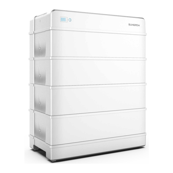
Product Description Product Introduction Brief Introduction The battery is designed for residential energy storage systems. The inbuilt battery manage- ment system monitors its operation and prevents the battery from operating beyond the specified limitations. This product is a high-voltage battery system with an operating voltage range between 150 V ~ 584 V. - Page 15 Nameplate The nameplate clearly indentifies the product. The nameplate must remain permanently attached to the product. You will find the following information on the nameplate: • SUNGROW logo and product model • Technical data • Product symbol DC circuit breaker Major Components Images are for reference only.
-
Page 16: Terminal Description
Configuration Table Battery Top cover Switch gear Model Base Side cover module SBR096 SBR128 SBR160 SBR192 SBR224 SBR256 Terminal Description All electrical terminals are located at the switch gear. Images are for reference only. The actual products received may differ. -
Page 17: Symbols On The Product
User Manual 2 Product Description Symbols on the Product Symbol Explanation Pay attention to the danger. Do not operate this product in the live status! No open flames Do not expose to flame, incinerate, puncture, or impact. Electric shock hazard Serviced by qualified personnel only. - Page 18 2 Product Description User Manual LED color LED state Definition indicator Normal operation (without fault) Slow blink The battery is at power-on or standby state (without fault). Blue Period: 2 s Fast blink The battery is at firmware update state. Period: 0.5 s A system fault has occured.
-
Page 19: Unpacking And Storage
• Check the inner contents for damage after unpacking. Contact SUNGROW or the transport company in case of any damage or incompleteness, and provide photos to facilitate services. Do not dispose of the original packing case. It is recommended to store the device in the original packing case when the device is decommissioned. -
Page 20: Storage
3 Unpacking and Storage User Manual Quantity Item Name Foot M5*14 hex socket screw 7 ~ 18 Expansion plug set M5 screw sets M6 fender washer Stud(optional) SUNCLIX Connector OT terminal Documents * Images are for reference only. The actual products received may differ. * If the top cover is C1, you will received M5*125 hex socket screws. -
Page 21: Mounting
Mounting Safety during Mounting This product or system must be operated by professionals! Failure to follow the safety instructions in this manual or operation of this product or system by non-professionals may cause severe personal injury or major prop- erty damage. Strictly follow local relevant standards and requirements in the whole process of installation. -
Page 22: Installation Tools
4 Mounting User Manual • In case of multiple batteries, reserve specific clearance between the batteries. Installation Tools Installation tools include but are not limited to the following recommended ones. If necessary, use other auxiliary tools on site. table 4-1 Tool specification Goggles Dust mask Protective gloves... -
Page 23: Pe Cable Preparation
User Manual 4 Mounting Utility knife Marker Rubber mallet Measuring tape Level Hammer drill (φ10) Phillips screwdriver Wrench (16mm、 (M4,M5,M6) 17mm、35mm) Hydraulic plier Heat gun Allen wrench (M5) MC4 Wrench Tube terminal Wire stripper MC4 terminal crimp- crimping tool ing tool(4–6 mm PE Cable Preparation Additional grounding cable is prepared by customers. -
Page 24: Assembling The Sunclix Connector
4 Mounting User Manual (1) Heat shrink tubing (2) OT/DT terminal - - End Assembling the SUNCLIX Connector During assembly, be careful not to contaminate, pull out, or shift, the seal in the ca- ble gland. A contaminated or shifted seal impairs strain relief and leak tightness. figure 4-1 SUNCLIX Connector Components 1: Spring 2: Sleeve... -
Page 25: Assembling The Communication Connector(Optional)
User Manual 4 Mounting step 2 Pry the connection open and pull the sleeve and the insert apart. step 3 Insert the stripped cable into the cable gland up to the stop. The stranded wire can be seen inside the spring. Press the spring down until it audibly snaps into place. step 4 Push the insert into the sleeve and tighten the cable gland (torque 2 N·m). - Page 26 4 Mounting User Manual step 1 Unscrew the swivel nut from the connector. step 2 Remove the inner rubber gasket. step 3 Insert the RJ45 plug into the front plug connector until there is an audible click, and install the rubber gasket. step 4 Tighten the swivel nut.
-
Page 27: Installing The Battery
User Manual 4 Mounting Installing the Battery The SBR128 mounting will be used as an example. The product with base A2 is taken as an example in the following installation steps. step 1 Install the feet of the battery. Method 1 Method 2 step 2 Align the base with the wall, and keep a distance of 30 mm to 45 mm between the base and the wall. - Page 28 4 Mounting User Manual figure 4-2 Layout of holes with the base A1 as reference A: Upper surface of the base B: Base A1(front view) C: Measurement baseline D: Base A1(top view) Mark the hole positions along a line vertical to the measurement baseline The feet of the base have been installed already.
- Page 29 User Manual 4 Mounting figure 4-3 Layout of holes with the base A2 as reference A: Upper surface of the base B: Base A2(front view) C: Base A2(top view) The feet of the base have been installed already. step 3 Drill the holes according to the marked positions, and install the expansion sleeves. Goggles and gloves are necessary when drilling holes for protection.
- Page 30 4 Mounting User Manual step 5 Place each battery module on top of the base. When carrying the battery module, always be aware of its weight of 33 kg. step 6 Fix the battery modules with the included screws.
- Page 31 User Manual 4 Mounting step 7 Connect the switch gear to the base. Ensure that the DC circuit breaker is disconnected. step 8 Fix the switch gear with the provided M5 screw or stud. The installation varies for products with different top covers. The product received shall prevail.
- Page 32 4 Mounting User Manual Case 2: The top cover is C2. When 4 or more than 4 battery modules are installed in one base, M5 screw set is required to secure the switch gear. The stud is mounted on the top of battery module.
- Page 33 User Manual 4 Mounting Case 2: The bracket is E2 The bracket is mounted on the top battery module. The mounting position can be fine-tuned through oval holes in the back. Goggles and gloves are necessary when drilling holes for protection. Shield the battery during drilling.
- Page 34 4 Mounting User Manual The installation method of communication connector G1 and communication con- nector G2 is the same, and here takes G1 as an example. For communication between the battery and the PCS. Connect the communication cable from the “COMM” terminal of the battery to the PCS. Strip the insulation layer of the commu- nication cable with a wire stripper, and lead the corresponding CAN1_H/CAN1_L signal ca- ble out.
- Page 35 User Manual 4 Mounting step 11 Place the top cover and fix it with the screws provided. The installation varies for products with different top covers. The product received shall prevail. Case 1: The top cover is C1. Case 2: The top cover is C2. The product with C1 is taken as an example in the following installation steps.
- Page 36 4 Mounting User Manual When 4 or more than 4 battery modules are installed in one base, side covers are required. - - End...
-
Page 37: Parallel System(Optional
Parallel System(Optional) Max.4 batteries can be connected in parallel to compatible PCS. Please refer to PCS man- ual for the compatibility details. Scope of Delivery Quantity Item Name Combiner box Bracket Expansion plug set M4 screw set COM2 connector SUNCLIX connector COM1 connector Battery connectors OT terminal... -
Page 38: Mounting The Combiner Box
5 Parallel System(Optional) User Manual Mounting the Combiner Box step 1 Install the wall-mounting bracket and mount the Combiner box to the bracket. - - End Terminal Description (Combiner Box) All electrical terminals are located at the bottom of the combiner box. figure 5-1 Terminals at the Bottom of the Combiner Box * The image shown here is for reference only. -
Page 39: Connection Diagram In Parallel System
User Manual 5 Parallel System(Optional) Description Label Communication terminal, connected to the battery COMM COM2 terminal P+ terminal, connected to the PCS positive terminal P+, P– P– terminal, connected to the PCS negative terminal Connected to the ground table 5-2 The label of COM2 terminal BMS1/CAN BMS2/CAN BMS3/CAN... - Page 40 5 Parallel System(Optional) User Manual • The COMM terminal of the battery is connected to the COM2 terminal of the combiner box. Signal cable 1 white and orange cable is used as BMS/CAN_H1; signal cable 2 or- ange cable is used as BMS/CAN_L1; signal cable 5 white and blue cable is used as BMS/CAN_H2;...
-
Page 41: Pe Cable Connection
User Manual 5 Parallel System(Optional) PE Cable Connection step 1 For the preparation of PE cable, refer to section "4.6 PE Cable Preparation". step 2 Remove the screw on the PE terminal and fasten the cable with a screwdriver. step 3 Apply paint to the grounding terminal to ensure corrosion resistance. - - End Battery Connection 5.6.1 Assembling the Battery Connectors... -
Page 42: Installing The Battery Connectors
5 Parallel System(Optional) User Manual step 3 Lead the cable through cable gland, and insert the crimp contact into the insulator until it snaps into place. Gently pull the cable backward to ensure firm connection. Tighten the ca- ble gland and the insulator (torque 2.5 N.m to 3 N.m). step 4 Check for polarity correctness. -
Page 43: Com2 Cable Connection
User Manual 5 Parallel System(Optional) step 4 Ensure that the connectors are securely in place. - - End COM2 Cable Connection 5.8.1 Assembling the COM2 Cable Connector The BMS3/CAN terminal is used as an example for description. step 1 Unscrew the swivel nut from the connector. step 2 Take out the terminal block. - Page 44 5 Parallel System(Optional) User Manual step 4 Strip the cable with a wire stripper. step 5 Crimp the cord end terminal。 step 6 Plug the wires into the corresponding terminal according the labels on the bottom of the device. step 7 Pull the wires outward to check whether they are firmly installed. step 8 Insert the terminal block into the connector until it snaps into place with an audible click.
-
Page 45: Installing The Com2 Cable Connector
User Manual 5 Parallel System(Optional) step 9 Fasten the swivel nut. - - End 5.8.2 Installing the COM2 Cable Connector step 1 Remove the waterproof lid from the COM2 terminal. step 2 Insert the COM2 connector into COM2 terminal on the bottom of the combiner box until there is an audible click. -
Page 46: Com1 Cable Connection
5 Parallel System(Optional) User Manual COM1 Cable Connection step 1 For the assembly of the COM1 connector, refer to the section"4.8 Assembling the Communi- cation Connector(Optional)". If the COM1 connector received is G2, please skip this step. step 2 Insert the COM1 connector into COM1 terminal on the bottom of the combiner box. Tighten the swivel nut. -
Page 47: Commissioning
Commissioning Inspection before Commissioning Check the following items before starting the battery: • Check that the battery system has been installed completely. • Check that the appearance of the battery system is intact. • Check that the battery system output wiring harness is correctly connected to the positive and negative terminals of the battery and PCS to avoid misconnection and reverse connection. -
Page 48: First Power-On Calibration
(the indicator light is red), and obtain fault in- formation through iSolarCloud to contact SUNGROW to repair the battery system. First Power-on Calibration The battery can only be connected to PCS produced by SUNGROW, as listed below: •... - Page 49 User Manual 6 Commissioning When the battery works with PCS, it automatically calibrates every half year. Calibration is done automatically by batteries and PCS given that there is electricity in the grid or PV modules to charge and discharge batteries. step 1 The battery automatically issues discharge instructions to PCS, which discharge the battery to 0% SOC at rated current.
-
Page 50: Decommissioning The Battery
- - End Contact SUNGROW to dispose of the battery. If a combiner box is used, power off the DC and AC sides of the PCS, and discon- nect MCBs of all battery RACKs before replacing the battery RACK. -
Page 51: Troubleshooting And Maintenance
717, 732– 737, Battery so, contact the battery manufacturer. If not, contact 739, 832–837, fault SUNGROW. 839, 844, 864, 866– 868, 870 3. In case of abnormal battery temperature, take meas- ures to change the ambient temperature, such as improv- ing heat dissipation conditions. - Page 52 8 Troubleshooting and Maintenance User Manual The power station scale, installation location and on-site environment affect the mainte- nance cycle of this product. In sandy or dusty environments, it is necessary to shorten the maintenance cycle and increase the frequency of maintenance. Maintenance performed once a year Inspection item Inspection method...
- Page 53 Check whether the grounding is correct. Check whether the current, voltage and temperature in Function inspection the operation record of the battery module are within the operating ranges. The battery capacity can be automatically calibrated, and it is supported only by the Sungrow PCS system.
-
Page 54: Appendix
Appendix Technical Data table 9-1 Technical parameters of high voltage LFP battery(SBR096 / SBR128 / SBR160). Parameters SBR096 SBR128 SBR160 System Data Battery Type LiFePO4 Prismatic Cell Battery 3.2 kWh, 33 kg Module Energy (usa- 9.6 kWh 12.8 kWh 16 kWh... - Page 55 User Manual 9 Appendix Parameters SBR096 SBR128 SBR160 Over current protection Over / under temperature protection DC breaker General Data Dimensions 625 * 545 * 330 625 * 675 * 330 625 * 805 * 330 (W*H*D) Weight 114 kg...
- Page 56 9 Appendix User Manual Parameters SBR192 SBR224 SBR256 Max. charging / dis- charging current: 30 A continuous Max. charging / dis- 42 A charging current: Depth of Discharge Max. 100% DOD(settable) Short circuit current 3500 A Display SOC indicator, Status indicator Communication interface Protection...
-
Page 57: Quality Assurance
After replacement, unqualified products shall be processed by SUNGROW. • The customer shall give SUNGROW a reasonable period to repair the faulty device. Exclusion of Liability In the following circumstances, SUNGROW has the right to refuse to honor the quality guarantee:... -
Page 58: Contact Information
The fault or damage is caused by installation, repairs, modification, or disassembly per- formed by a service provider or personnel not from SUNGROW. • The fault or damage is caused by the use of non-standard or non-SUNGROW compo- nents or software. •... - Page 59 Tokyo Seoul + 81 3 6262 9917 +82 70 7719 1889 service@jp.sungrowpower.com service@kr.sungrowpower.com Malaysia Philippines Sungrow SEA Sungrow Power Supply Co., Ltd Selangor Darul Ehsan Mandaluyong City +60 19 897 3360 +63 9173022769 service@my.sungrowpower.com service@ph.sungrowpower.com Thailand Spain Sungrow Thailand Co., Ltd.
- Page 60 9 Appendix User Manual Vietnam Belgium, Netherlands and Luxembourg (Benelus) Sungrow Vietnam +31 853 018 234 (only for Netherlands) Hanoi service@sungrow-emea.com +84 918 402 140 service@vn.sungrowpower.com Poland +48 221530484 service@sungrow-emea.com...
Need help?
Do you have a question about the SBR096 and is the answer not in the manual?
Questions and answers